
203 - Walkie-talkie MIDLAND - Free user manual and instructions
Find the device manual for free 203 MIDLAND in PDF.
| Product Type | CB Transceiver |
| Brand | Midland |
| Model | 203 |
| Dimensions | 124 x 38 x 190 mm |
| Weight | 1.2 kg |
| Power Supply | 12.6 V DC ±10% |
| Power Consumption | FM: 1.3 A; AM: 1.8 A |
| Frequency Range | 26.565 - 27.405 MHz |
| Number of Channels | 40 (4 bands: IT, EU, PL, D3) |
| Modulation | AM / FM |
| Output Power | 1 to 4 W |
| Receiver Sensitivity | > 1 μV for 20 dB SINAD |
| Squelch | Adjustable from 1.2 μV to 1 mV |
| Antenna Connector | PL type (coaxial 50 Ω) |
| Microphone Connector | 4 pins |
| External Speaker | 3.5 mm jack, 4 Ω, 3-10 W |
| Display | Digital display of active channel |
| Priority Channels | 9 (emergency) and 19 (traffic) |
| PTT Button | Yes, on the microphone |
| Included Accessories | Microphone, mounting bracket, power cord |
| Warranty | 24 months |
| Maintenance and Cleaning | Avoid moisture, extreme temperatures, and chemicals |
| Safety | Never use without an antenna connected; disconnect power before maintenance |
Frequently Asked Questions - 203 MIDLAND
User questions about 203 MIDLAND
0 question about this device. Answer the ones you know or ask your own.
Ask a new question about this device
Download the instructions for your Walkie-talkie in PDF format for free! Find your manual 203 - MIDLAND and take your electronic device back in hand. On this page are published all the documents necessary for the use of your device. 203 by MIDLAND.
USER MANUAL 203 MIDLAND
Midland 203 is the brand new Multi Standard CB transceiver, essential in its functionalities but with advanced performances: Phase Locked Loop circuitry gives precise frequency control and stability over all channels (pinpoint channel tuning accuracy with separate scan up and down controls); the ceramic filters give superior selectivity and freedom from adjacent channel interference.
Midland 203 is supplied with a microphone, mounting bracket and power supply cable.
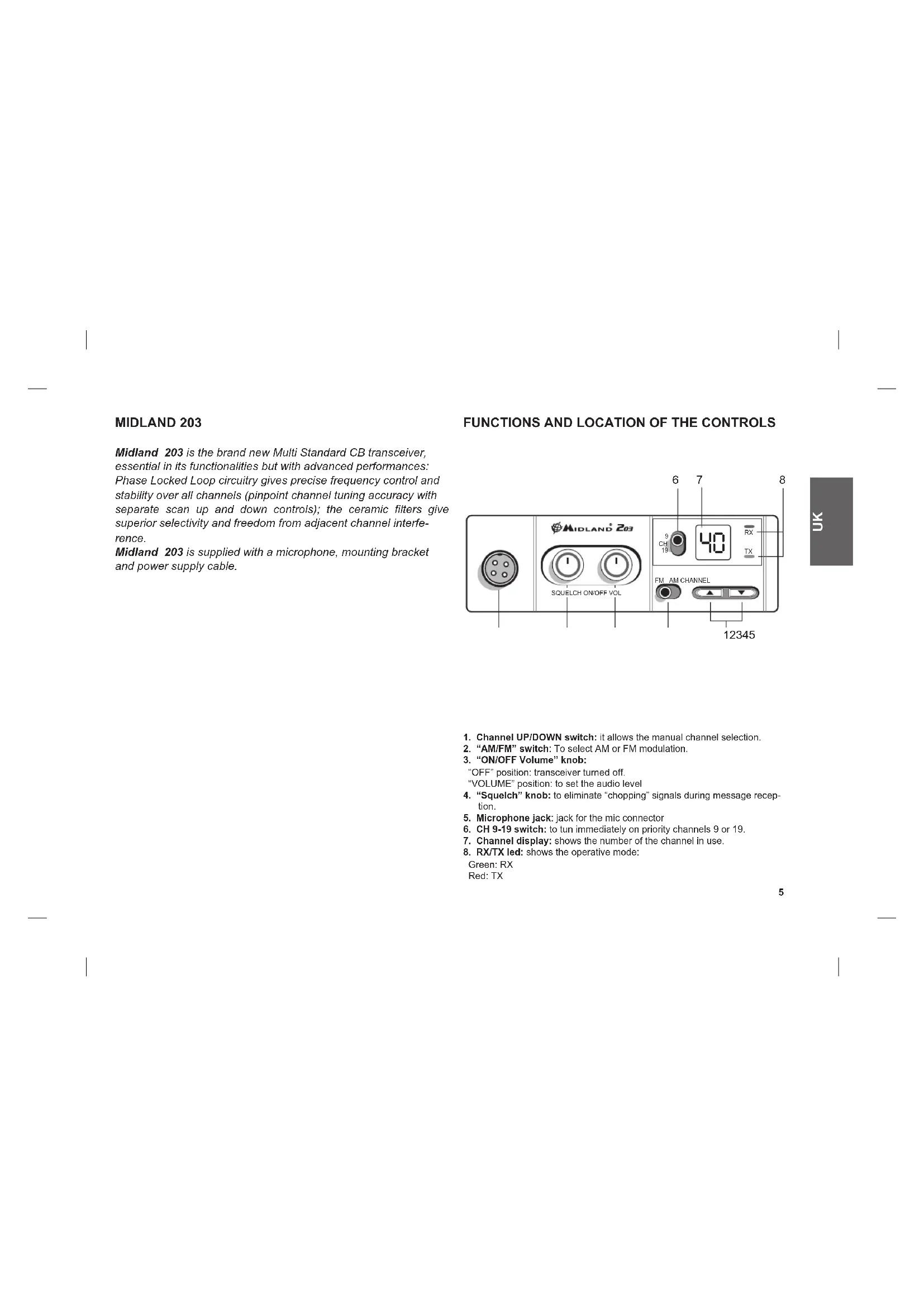
FUNCTIONS AND LOCATION OF THE CONTROLS
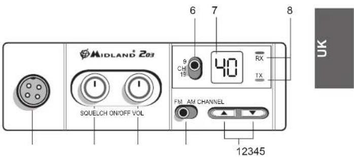
- Channel UP/DOWN switch: it allows the manual channel selection.
- "AM/FM" switch: To select AM or FM modulation.
- "ON/OFF Volume" knob:
"OFF" position: transceiver turned off.
"VOLUME" position: to set the audio level - "Squelch" knob: to eliminate "chopping" signals during message reception.
- Microphone jack: jack for the mic connector
- CH 9-19 switch: to tun immediately on priority channels 9 or 19.
- Channel display: shows the number of the channel in use.
- RX/TX led: shows the operative mode
Green:RX Red:TX
REAR PANEL
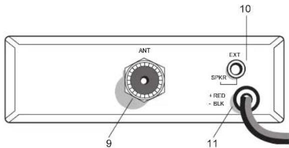
- Antenna connector: PL connector type
- EXT SPKR jack: external loudspeaker jack (the internal loudspeaker will be excluded)
- Power supply cable: power 12,6V DC
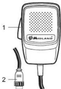
MICROPHONE
- PTT: transmission button
- 4 pin microphone connector
INSTALLATION
An extremely important requirement is the ease of installation and removal for those occasions when you might want to remove the unit for service and maintenance.
The most common mounting position for a transceiver is under the dashboard directly over the drive shaft hump. Do not mount the transceiver in the path of the heater or air conditioning.
Take your time and plan your installation carefully. When you have determined the best location for mounting, use the mounting bracket as a template to mark mounting holes. Take care when you drill the holes that you do not drill into wiring, trim or other accessories.
Mount in position with bolts, lock washers and nuts or self-threading screws. Insert the power cable with lighter plug into the vehicle's cigarette lighter cord. Before operating, you must install and connect your antenna system. The lead from the antenna you've installed should be connected to the antenna coaxial connector. If you are using an external speaker, connect it to the EXT-SPKR jack.
INSTALLING AN ANTENNA
A mobile antenna system is not limited to the antenna only. The transmission line, as well as the vehicle, are important factors in the total antenna system. Therefore, you must use the correct type of transmission line and mount the antenna securely in a position that will give you optimal results.
Use coaxial cable with an impedance of 50 Ohms. Generally speaking, you should keep the length of the transmission line to a minimum.
The above discussion is as important for reception as it is for the transmission. If a mismatch exists between the antenna and the receiver, the excellent sensitivity and signal-to-noise radio of the receiver circuit will be defeated.
Useful information
- Place the antenna as high as possible
- The longer the antenna is, the better will be the performance
- Mount the antenna and keep antenna cable away from noise sources, such as the ignition switch, gauges, etc.
- Make sure you have a solid metal-to-metal ground connection.
- Prevent cable damage during antenna installation.
There are many types of mobile CB antennas: a full quarter-wave length whip, a center loaded whip, top loaded whip and the base loaded type. For a greater efficiency it is recommended 2.5 m long, full quarter-wave whip.
Antenna length is directly related to efficiency.
A vertically polarized whip antenna is best suited for mobile service. It is omnidirectional.
Roof mount is the best ever as in this position the antenna radiates equally in all directions.
WARNING: To avoid damage, never operate your CB radio without connecting a proper antenna. A periodical control of the cable and of the S.W.R. is recommended.
HOW TO OPERATE YOUR MIDLAND 203
After have installed and cabled your CB transceiver, follow these steps to operate with your device:
- Screw the microphone plug into the microphone jack and check that the unit is properly connected
- Make sure your antenna is connected to the antenna connector.
- Make sure the SQUELCH control is turned fully counter clockwise.
- Select AM or FM mode
- Turn on the unit and select the frequency band to use
- Adjust the volume to a suitable listening level
- Select your desired channel.
- Adjust Squelch to cut out annoying background noise when no signal is being received.
- To transmit, press the PTT button and speak in a normal tone of voice.
- To receive, release the PTT button.
The frequency bands must be chosen according to the country where you are going to operate.
Your Midland 203 can be set on 4 different frequency bands:
IT(it): 40CH 26.965 MHz - 27.405 MHz 4W AM/FM
EU(EU): 40CH 26.965 MHz - 27.405 MHz 1W AM/4W FM
PL(PL): 40CH 26.960 MHz - 27.400 MHz 4W AM/FM
D3(d3): 80CH from CH1 to CH40 26.965MHz -27.405 MHz 1W AM/4W FM from CH41 to CH80 26.565MHz -26.955 MHz 4W FM
Procedure:
- Switch off the unit.
-
Turn the device on and contemporary keep pressed the UP/DOWN buttons.
-
Select the desired frequency band by pushing the UP/DOWN buttons
- To confirm the selection, press the PTT button or wait for 5 seconds. Note: Once have set the frequency band, every time you turn on the radio, the display will show for 1 second the frequency band in use. To change the frequency band, follow the steps upon described.
SQUEELCH
The Squelch function cuts out annoying background noise when no signal is being received.
To do this, set the Channel Selector to a channel where no signals are present or wait until signals cease on your channel. Then, rotate the Squelch control in a clockwise direction to the point where the background noise just stops. Now, when a signal is present, you will hear it, but will not be disturbed by noise on the channel between signals.
When properly set, the Squelch keeps the receiver "dead" until a signal comes in on that channel. However, do not set the Squelch too high, otherwise weak signals will not be able to open the Squelch circuit. To receive very weak signals, it is better to leave Squelch set to the minimum position by rotating the control maximum counterclockwise.
EMERGENCY CHANNELS (CH 9-19)
Midland 203 is equipped with a switch that allows to be immediately set on the Priority cannels 9 and 19.
CH 9 is for Emergency communications, while CH 19 is used for asking road condition information.
The centre position of the switch is for tuning on the latest selected channel.
A 4 Ohm speaker, rated at 3-10 watts, should be used for this function. Plug the speaker into the EXT SPKR jack at the rear of the transceiver. When the external speaker is plugged in, the internal speaker is disconnected.
WARRANTY
Midland will repair or replace, at its option without charge, any Midland 203 transceiver which fails due to a defect in material or workmanship within TWO Years following the initial consumer purchase.
In the event of a product defect, please return it to the authorized customer service or to the Manufacturer himself.
To make use of this warranty, it is necessary to return to the authorized service centre:
The affected product (or accessory)
The original proof of purchase, which clearly indicates the name and address of the seller and the date and place of purchase.
This warranty does not apply to accidents of any kind, exposure to pressure, extreme temperatures (outside of -10^ to 55^ ), submersion water damage, battery leak or abuse.
This warranty does not include the cost of labor for removal or re-installation of the product in a vehicle or other mounting.
TECHNICAL SPECIFICATIONS
RECEIVER
Frequency coverage from 26.565 to 27.405 MHz
Sensitivity better than 1.0 V for 20 dB SINAD
Adjacent Channel Rejection 60 dB at 10 kHz; 70 dB for 20 KHz
Intermediate Frequency. 1st IF=10.7 MHz; 2nd IF=455 KHz
Audio Output power 4 watts max
Frequency Response (-6dB) 6 dB: 450-2500 Hz
Squelch. adjustable from 1.2 V to 1mV
TRASMITTER
Frequency coverage from 26.565 to 27.405 MHz
Duty cycle 5/5/90
Output Power 1/4 W
Type of modulation AM/FM
Max Deviation .2.0 KHz FM; 80% AM
Spurious Radiation 62 dB or better
Frequency Tolerance 0.002%
Power supply 12,6 Vdc ±10%
Current Drain FM: 1.3 A; AM: 1.8 A
Dimensions 124x38x190 mm
Weight 1.2 kg
All specifications are subject to change without notice.
A readily accessible disconnect device shall be incorporated in the installation wiring. The disconnect device shall disconnect both poles simultaneously.
Hereby, CTE International declares that this Midland 203 is in compliance with the essential requirements and other relevant provisions of Directive 1999/5/EC. A copy of Declaration of Conformity can be found at: www.midlandradio.eu
MIDLAND 203
EU (EU): 40 CH 26,965 MHz - 27,405 MHz 1 W AM/4 W FM
PL (PL): 40 CH 26,960 MHz -27,400 MHz 4 W AM/FM
26,965 MHz - 27,405 MHz 1 W AM/4 W FM
Max Frequenzhub. 2.0 kHz FM; 80% AM
26,965 MHz - 27,405 MHz 1 W AM/4 W FM;
du canal 41 au canal 80:26,565 MHz -26,955 MHz 4 W FM
Procedure:
26.965MHz - 27.405 MHz 1W AM/4W FM
do CH41 para CH80 26.565MHz - 26.955 MHz 4W FM
Procedimento
CANAIS DA EMERGÊNCIA (CH 9-19)
Voeding 12.6 Vdc +10%
OBUHE: 26.565do27.405M
Pabouy nckn (1 yac). TX 5 %, RX 5 %, stand-by 90 %
ПИТАнг... 12,6В пот. тoka +/- 10%
T6apnbl 124x38x190 MM
Bec. 1.2 K
PPIEMHNIK: UyCTBHTeNbHocTb .nyuue yem 1,0 MKB npn 20 dS SINAD
IodabnneHne no6ohbIX kaHaNoB 60d5
Ppomexkytohhe yactotbl. 1N4:10,7MgI I N4:455K
BbIXoHaH aYdno MOuHocTb. MaKc 4BT
IPEDAATIK: BbIXoHnA MoUHocTb 1Bt n4Bt
(B3ABNCMOCTNOTBbIpaHHOROdnana30HaCACTOT)
Modynau. AM/FM
MaKc.deBnaucn. 1.8 Kf FM; 95% AM
YpOBeH no6OHybIX n3nyueHn. He xyKe 60 dE
DonyctHMoe OTKIOHHe HcTOT. 0.002%
Notpe6neHne ToKa.. FM (4Bt): 1.3 A; AM: 1.8A
PON3BedeHO HNNHNPOTNPOBAHO
CTE INIHTREPHeHn c.p.n.-yn.P.CeBaapn7-42124 MaHkacalb,PeJknO 3MmHn,ITaJIIN
MmnpTepePoccn-3AOAanH-CBra3b
InrepeHcAaT:www.midland.ru
Aqpec:MockBa,105187,ΦoptyHATOBxAN 31A,ctp.2
Hacmou CTE Intemational 3aennem, mdo dahbu npodym coomeemcmsey
mpe6o8aHua dupekmuoe EC 1999/5/EC.

Produced or imported by:
CTE INTERNATIONAL s.r.l.
Via.R.Sevardi 742124 Mancasale Reggio Emilia Italy
Imported by:
ALAN UK
Unit 2, Callenders, Paddington Drive, Churchward Park, Swindon, Wiltshire, SN5 7YW - UK
www.alan-uk.com
The use of this transceiver can be subject to national restrictions. Read the instructions carefully before installation and use.
Importado por:
ALAN COMMUNICATIONS, SA

Brand : MIDLAND
Model : 203
Category : Walkie-talkie