SHZ 100 LCD - Boiler STIEBEL ELTRON - Free user manual and instructions
Find the device manual for free SHZ 100 LCD STIEBEL ELTRON in PDF.

Frequently Asked Questions - SHZ 100 LCD STIEBEL ELTRON
User questions about SHZ 100 LCD STIEBEL ELTRON
0 question about this device. Answer the ones you know or ask your own.
Ask a new question about this device
Download the instructions for your Boiler in PDF format for free! Find your manual SHZ 100 LCD - STIEBEL ELTRON and take your electronic device back in hand. On this page are published all the documents necessary for the use of your device. SHZ 100 LCD by STIEBEL ELTRON.
USER MANUAL SHZ 100 LCD STIEBEL ELTRON
natural_image
Technical line drawing of a rectangular enclosure or enclosure with vertical and horizontal lines, no text or symbols present.BESONDERE HINWEISE
BEDIENUNG
4.3.2 Symbol Service/Fehler

Hinweis
text_image
QR code image containing encoded data, no visible human-readable textwww.stiebel-eltron.com/registration
INSTALLATION
8. Sicherheit
text_image
Technical diagram showing structural components and assembly of a battery or enclosure, with labeled parts 1, 2, and 3.natural_image
Illustration of a person installing or adjusting a large cylindrical device on a table, with no visible text or symbols.text_image
S E A R E A D0000040165text_image
Technical diagram of a mechanical assembly with labeled parts 1 and 2natural_image
Technical line drawing of a mechanical assembly with cross-sectional and top views (no text or symbols)text_image
L3L2L1N 5 6 3 2 L1 L2 L3 N 26_02_07_0256_line
| X | Series 1 | Series 2 | Series 3 | Series 4 | Series 5 | |---|---|---|---|---|---| | 30 | 2 | 1 | 1 | 1 | 1 | | 50 | 3.5 | 1.5 | 1.2 | 1 | 0.8 | | 80 | 5.5 | 2.5 | 1.8 | 1.5 | 1 | | 100 | 6.7 | 3.5 | 2.2 | 2 | 1.2 | | 120 | 8 | 4.2 | 2.8 | 2.5 | 1.5 | | 150 | 10 | 5 | 3.2 | 2.8 | 1.8 |line
| X | Series 1 | Series 2 | Series 3 | Series 4 | Series 5 | |---|---|---|---|---|---| | 30 | 2.8 | 1.2 | 0.9 | 0.7 | 0.5 | | 50 | 4.6 | 2.2 | 1.4 | 1.1 | 0.8 | | 80 | 7.3 | 3.6 | 2.3 | 1.8 | 1.2 | | 100 | 9.1 | 4.5 | 2.9 | 2.3 | 1.4 | | 120 | 11.0 | 5.5 | 3.5 | 2.7 | 1.8 | | 150 | 13.7 | 6.9 | 4.4 | 3.3 | 2.2 |X Nenninhalt in |
Y Dauer in h
1 1 kW
2 2 kW
3 3 kW
4 4 kW
5 6 kW
1.1 Safety instructions 27
1.2 Other symbols in this documentation 28
1.3 Units of measurement 28
- Safety 28
2.1 Intended use 28
2.2 Safety instructions 28
2.3 Test symbols 28
-
Appliance description 29
-
Settings 30
4.1 Controls and standard display 30
4.2 Energy saving settings in the standard display 30
4.3 Other possible symbols in the standard display 32
4.4 Standard settings 32
4.5 Menu settings 33
4.6 Starting, stopping and setting the menu limit ____ 34
-
Cleaning, care and maintenance 34
-
Troubleshooting 34
INSTALLATION
- Safety 35
7.1 General safety instructions 35
7.2 Regulations, standards and instructions 35
7.3 Water installation 35
- Appliance description 35
8.1 Standard delivery 35
8.2 Accessories 35
- Preparations 35
9.1 Installation site 35
9.2 Mounting bracket 35
9.3 Power cable 36
- Preparing for installation 36
10.1 Water connection 36
10.2 Appliance installation 36
10.3 Power supply 36
10.4 Completing installation 37
- Commissioning 37
11.1 Commissioning 37
11.2 Recommissioning 37
- Settings 37
12.1 Switching on commercial mode 37
12.2 Switching on reverse control 37
-
Shutting down 37
-
Troubleshooting 38
-
Maintenance 39
15.1 Safety assembly 39
15.2 Draining the appliance 39
15.3 Descaling 39
15.4 Anti-corrosion protection 39
- Specification 40
16.1 Dimensions and connections 40
16.2 Wiring diagrams and connections 41
16.3 Heat up diagrams 45
16.4 Fault conditions 45
16.5 Details on energy consumption 46
16.6 Data table 46
GUARANTEE
ENVIRONMENT AND RECYCLING
SPECIAL INFORMATION
- The appliance may be used by children aged 3 and older and persons with reduced physical, sensory or mental capabilities or a lack of experience and know-how, provided that they are supervised or they have been instructed on how to use the appliance safely and have understood the resulting risks. Children aged 3 to 8 years may only operate the tap connected to the appliance. Children must never play with the appliance. Children must never clean the appliance or perform user maintenance unless they are supervised.
- The connection to the power supply is only permissible as a permanent connection in conjunction with the removable cable grommet. Ensure the appliance can be separated from the power supply by an isolator that disconnects all poles with at least 3 mm contact separation.
- Fix the appliance in position as described in chapter “Installation / Preparations”.
- Observe the maximum permissible pressure (see chapter Installation / Specification / Data table).
- Install a residual current device (RCD).
Sealed unvented operating mode:
- The appliance is pressurised. During the heat-up process, expansion water will drip from the safety valve.
- Regularly activate the safety valve to prevent it from becoming blocked, e.g. by limescale deposits.
- Drain the appliance as described in chapter “Installation / Maintenance / Draining the appliance”.
- Install a type-tested safety valve in the cold water supply line. Please note that, depending on the static pressure, you may also need a pressure reducing valve.
- Size the drain so that water can drain off unimpeded when the safety valve is fully opened.
- Fit the discharge pipe of the safety valve with a constant downward slope and in a room free from the risk of frost.
- The safety valve discharge aperture must remain open to atmosphere.
OPERATION
1. General information
The chapters “Special Information” and “Operation” are intended for both the user and qualified contractors.
The chapter "Installation" is intended for heating contractors.

Note
Read these instructions carefully before using the appliance and retain them for future reference.
Pass on the instructions to a new user if required.
1.1 Safety instructions
1.1.1 Structure of safety instructions

KEYWORD Type of risk
Here, possible consequences are listed that may result from failure to observe the safety instructions.
▶ Steps to prevent the risk are listed.
1.1.2 Symbols, type of risk
| Symbol | Type of risk |
 | Injury |
 | Electrocution |
 | Burns(burns, scalding) |
1.1.3 Keywords
| KEYWORD | Meaning |
| DANGER | Failure to observe this information will result in serious injury or death. |
| WARNING | Failure to observe this information may result in serious injury or death. |
| CAUTION | Failure to observe this information may result in non-serious or minor injury. |
1.2 Other symbols in this documentation

Note
General information is identified by the symbol shown on the left.
▶ Read these texts carefully.
Symbol Meaning
Material damage
(appliance, consequential and environmental damage)

Appliance disposal
This symbol indicates that you have to do something. The action you need to take is described step by step.
1.3 Units of measurement

Note
All measurements are given in mm unless stated otherwise.
2. Safety
2.1 Intended use
The appliance is intended for heating domestic hot water and can supply one or more draw-off points, depending on the operating mode.
This appliance is designed for domestic use. It can be used safely by untrained persons. The appliance can also be used in a non-domestic environment, e.g. in a small business, as long as it is used in the same way.
Any other use beyond that described shall be deemed inappropriate. Observation of these instructions and of instructions for any accessories used is also part of the correct use of this appliance. Any modifications or conversions to the appliance void all warranty rights.
2.2 Safety instructions

WARNING Burns
During operation, the tap or safety assembly can reach temperatures in excess of 60 °C.
There is a risk of scalding at outlet temperatures in excess of 43 °C.

WARNING Injury
The appliance may be used by children aged 3 and up and persons with reduced physical, sensory or mental capabilities or a lack of experience provided that they are supervised or they have been instructed on how to use the appliance safely and have understood the resulting risks. Children aged 3 to 8 years may only operate the tap connected to the appliance. Children must never play with the appliance. Children must never clean the appliance or perform user maintenance unless they are supervised.

Material damage
Ensure that the appliance, water pipes and safety valves are free from the risk of frost. If you disconnect the appliance from the power supply, it is no longer protected against frost or corrosion.
- Never interrupt the power supply to the appliance.

Note
Sealed unvented operating mode: The appliance is under pressure. During the heat-up process, expansion water will drip from the safety valve. If water continues to drip when the heat-up process is completed, please inform your qualified contractor.

Note
Open vented operating mode: Whenever water is heated up, expansion water will drip from the spout.
2.3 Test symbols
See type plate on the appliance.
3. Appliance description
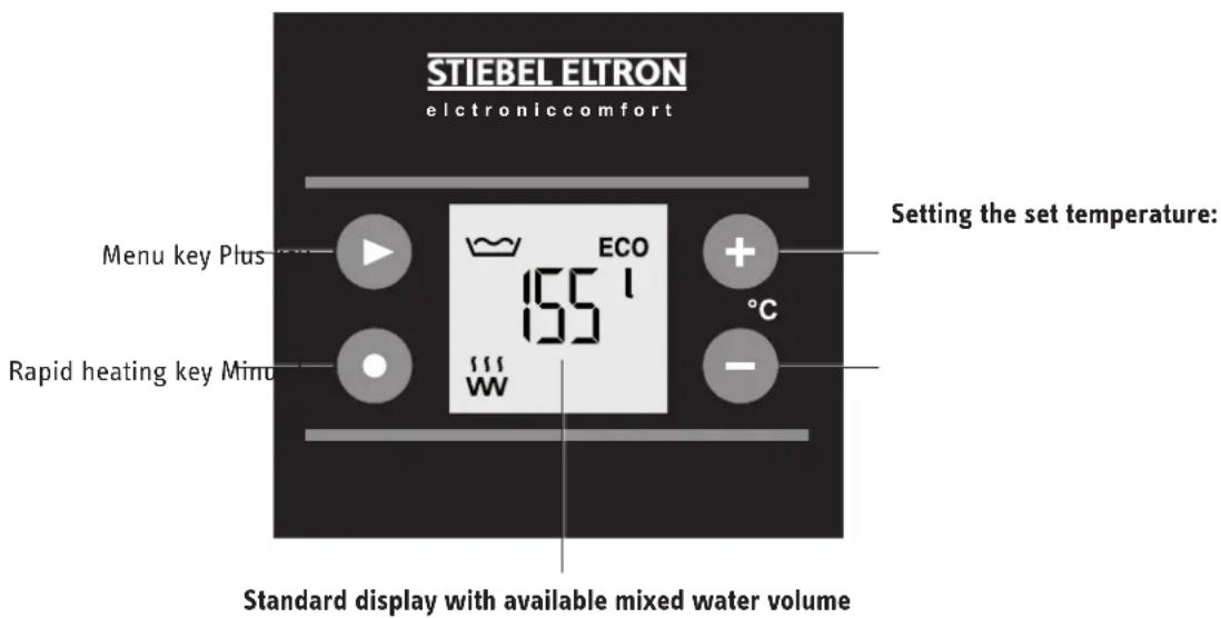
The appliance electrically heats domestic hot water with the connected heating output or with rapid heating. The electronic control unit makes energy saving adjustments easier. Subject to the power supply and your usage pattern, the water is heated up automatically to the set temperature. The standard display tells you about the available mixed water volume, the heat-up status and ECO mode. In addition, any faults and scale build-up on the flanged immersion heater are shown.
The internal steel cylinder is coated with special directly applied enamel and is equipped with an impressed current anode. When the power supply is on, the anode actively protects the internal cylinder from corrosion.
The appliance is protected from frost in all operating modes when the power supply is present. The appliance starts and stops at the right times when the water has been sufficiently heated. The water supply lines and the safety assembly are not protected against frost by the appliance.
You can use the appliance in single circuit, dual circuit or manual rapid heat-up operation.
Single circuit operation
In this operating mode, the appliance heats up the water automatically with the connected heating output at any set temperature setting.
Dual circuit operation
During off-peak tariff periods (power supply utilities' enable times), the appliance automatically heats up the water content with the connected heating output at any set temperature setting. You can also start rapid heating.
Manual rapid heat-up operation
The appliance heats the water if the rapid heating key has been pressed. Once the selected temperature has been reached, the appliance switches off and does not restart.
text_image
STIEBEL ELTRON elctroniccomfort Menu key Plus ECO 155°C Rapid heating key Minu Standard display with available mixed water volume Setting the set temperature:4. Settings
4.1 Controls and standard display
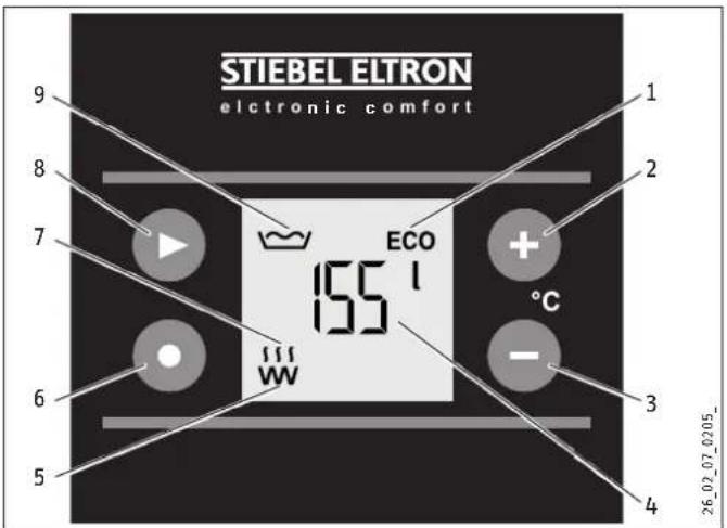
text_image
STIEBEL ELTRON electronic comfort 1 2 ECO + 155 l °C 3 - 1 W 155 W 26_02_07_0205_1 ECO mode symbol
2 Plus key
3 Minus key
4 Mixed water volume in I display
5 Radiator symbol
6 Rapid heating key
(in dual circuit or manual rapid heat-up operation)
7 Heat-up symbol
8 Menu key
9 Mixed water volume symbol
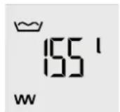
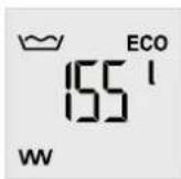
4.1.1 Mixed water volume display

Note
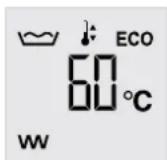
If you have adjusted the set temperature to less than 40^ C, the selected set temperature is displayed rather than the mixed water volume.
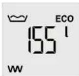
The currently available mixed water volume at 40 °C and at 15 °C cold water temperature is shown.
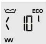
If there is currently less than 10 l mixed water available, "< 10 l" is shown.
DHW demand for Mixed water volume at 40 °C
Bath 120-150 I
Shower 30-50 |
Hand washing 2-5 l
The mixed water volume that can be achieved is dependent on the cylinder size and the selected set temperature.
4.1.2 Heat-up symbol
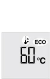
The symbol appears when the appliance is heating up water.
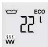
4.2 Energy saving settings in the standard display
4.2.1 ECO mode symbol
ECO Comfort (factory setting)
This energy saving mode always offers you the maximum amount of hot water and therefore maximum comfort.
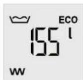
ECO symbol appears.
In ECO Comfort energy saving mode, the set temperature is automatically reduced to 60 °C if a higher set temperature is selected:
- 1 week after commissioning (factory setting: 85 °C)
- 1 week after selecting a set temperature above 65 °C
You can switch on this mode straight after commissioning by setting the set temperature to 60 °C or lower (see chapter "Standard settings / Setting the set temperature").
ECO Plus (with single circuit operation)
This energy saving mode offers you the advantage of energy savings, as reheating is only carried out after a significant volume of DHW is drawn off.
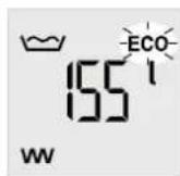
ECO symbol flashes
The set temperature is automatically set immediately to 60 °C.
In ECO Plus mode, the appliance heats up automatically to the set temperature once you have drawn off approx. 40 % of the cylinder content.
You can select this mode in the menu (see chapter "Menu settings / Displaying and adjusting ECO mode").

Note
If you change the set temperature in ECO Plus mode, the appliance switches automatically to ECO Comfort mode.
ECO Dynamic (with single circuit operation)
This energy saving mode allows you to achieve maximum energy efficiency through automatic dynamic matching to your draw-off patterns.
ECO Dynamic mode works best if you always require comparable volumes of hot water at the same time of day, regardless of the day of the week.
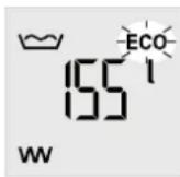
ECO symbol flashes
The set temperature is automatically set immediately to 60 °C.
When you select ECO Dynamic mode, the appliance evaluates your draw-off times and quantities for a week. At this time, the appliance initially operates in ECO Comfort mode.
After analysing, the calculated mixed water volume is made available, subject to the day and time. Up to 60 % of the cylinder content can be drawn off before the appliance reheats. If the currently available mixed water volume is not sufficient for the expected draw-off, the entire cylinder content is heated in good time to 60 °C.
If the draw-off times and volumes change, the appliance analyses the changes and adjusts the available mixed water volume as required.
You can select this mode in the menu (see chapter "Menu settings / Displaying and adjusting ECO mode").

Note
If you change the set temperature in ECO Dynamic mode, the appliance switches automatically to ECO Comfort mode.
4.2.2 Commercial mode
The heating contractor can adjust the appliance for commercial applications, e.g. in doctors' practices or butchers' shops (see chapter "Installation / Settings"). The set temperature is then adjusted manually. The ECO mode menu setting is not possible in commercial mode.
4.2.3 Adjusted use of off-peak tariff periods (reverse control with dual circuit operation)
This function is not enabled in the factory settings. The contractor can switch on the appliance reverse control function (see chapter "Installation / Settings").
This means that the appliance evaluates the cheap rate periods of your power supply utility for 7 days to make the most of off-peak times.
During the analysis, the appliance heats the cylinder content ready for the start of the off-peak tariff period in case the set temperature is not reached.
The aim is to start heat-up at the right time so that the full cylinder content heated to the set temperature is only available to you at the end of the off-peak tariff period. This means less energy is required to maintain the water at this temperature, i.e. the standby energy consumption falls.
The appliance starts heating at the calculated time.
Heat-up symbol appears.
Once heat-up has finished, the heat-up symbol disappears.
If the set temperature is not reached, you can activate heat-up with rapid heating if required (see chapter "Standard settings / Rapid heating") in the off-peak tariff period, even before the automatic start time.
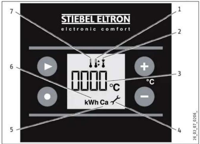
4.3 Other possible symbols in the standard display
text_image
STIEBEL ELTRON electronic comfort 7 1 2 6 0000 °C + 3 °C kWh Ca - 5 4 26_02_07_0206_1 Set temperature symbol
2 Temperature limit symbol
3 Value indication relative to the active symbol
4 Service/fault symbol
5 Scale build-up symbol
6 Energy consumption symbol
7 Outlet temperature symbol
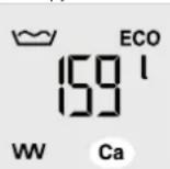
4.3.1 Scale build-up symbol

Note
If the scale build-up symbol "Ca" appears in the standard display, we recommend descaling the flanged immersion heater. Notify your local contractor.
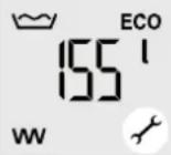
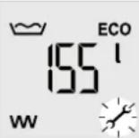
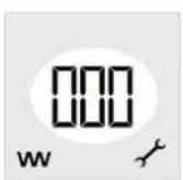
4.3.2 Service/fault symbol

Note
If the service/fault symbol appears in the standard display, inform your contractor. If the symbol flashes, no water is being heated and it is essential you inform your contractor.
4.4 Standard settings
4.4.1 Quick settings using the keys
You can make these settings directly in the standard display using the keys.

Note
After every adjustment, the appliance switches automatically to the standard display and saves the selected value.
4.4.2 Setting the set temperature


Adjust the set temperature from 20 to 85 °C using the plus and minus keys (factory setting).
Set temperature symbol appears.
If you change the set temperature of 60 °C in ECO Plus or ECO Dynamic mode, the energy saving mode is automatically switched to ECO Comfort. Further information can be found in chapter "Energy saving settings in the standard display".
4.4.3 Switching off
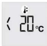

If you set the set temperature with the minus key to less than 20 °C, only frost protection remains active.
4.4.4 Rapid heating

Press the rapid heating key. Heat-up symbol appears.
Dual circuit operation
You can switch on rapid heating with the key. A remote control can also be installed for this purpose. The rapid heat-up function stops and will not restart when the selected temperature has been reached.
Manual rapid heat-up operation
You have to start the appliance with the rapid heating key. Once the selected temperature has been reached, the appliance switches off and does not restart.
4.5 Menu settings
4.5.1 General menu settings principle

Note
After every adjustment, the appliance switches automatically to the standard display and saves the selected value.

With the menu key, you call up all information and setting options one after the other. The relevant symbol appears.
4.5.2 Displaying the outlet temperature
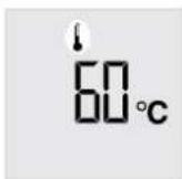

Outlet temperature symbol appears.
The current outlet temperature is displayed.
4.5.3 Setting the set temperature
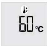

Set temperature symbol appears.

Adjust the set temperature from 20 to 85^ using the plus and minus keys.

4.5.4 Starting, stopping and adjusting the temperature limit

Temperature limit symbol appears. ☐ Temperature limit off (factory setting)
/ Temperature limit on

h the temperature limit on or off.

Adjust the temperature limit from 40 to 60 °C using the plus and minus keys.

Temperature limit on
The temperature limit symbol appears in the standard display. The selected temperature limit is also the maximum value for the set temperature.

Note
ECO Plus and ECO Dynamic can no longer be selected if the temperature limit is on.
4.5.5 Displaying and adjusting ECO mode

Note
In commercial mode (see chapter "Energy saving settings in the standard display / Commercial mode"), the ECO settings are skipped.
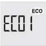

ECO mode symbol appears.
The current mode is displayed.
Scroll to the required ECO mode.
ECO1 ECO Comfort
ECO2 ECO Plus
ECO3 ECO Dynamic
ECO Comfort ECO1
This energy saving mode always offers you the maximum amount of hot water and therefore maximum comfort.
ECO Plus EC02
This energy saving mode offers you the advantage of energy savings, as reheating is only carried out after a significant volume of DHW is drawn off.
ECO Dynamic ECO3
This energy saving mode allows you to achieve maximum energy efficiency through intelligent dynamic matching to your draw-off patterns.
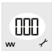
4.5.6 Displaying the energy consumption
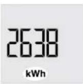

Energy consumption symbol appears.
An approximate value for the current energy consumption is displayed.
To reset the value to zero, hold the key for longer than 3 seconds.
hold
4.5.7 Displaying the level of scale build-up, switching automatic indications in the standard display on/off
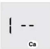

Scale build-up symbol appears.
The current level of scale build-up is displayed.
-- No / low scale build-up
CA Descaling of the flanged immersion heater recommended
! Automatic indication in the standard display on (factory setting)
☐ Automatic indication in the standard display off

tic indications in the
standard display off or on.
4.5.8 Displaying the service code
The service code gives the contractor information about the cause of a fault (see chapter "Troubleshooting").

Service code display
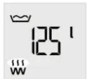
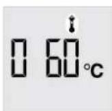
4.6 Starting, stopping and setting the menu limit
text_image
ECO 60°C
To set the menu limit, hold down the key for longer than 3 seconds until the set temperature display flashes up.
Set temperature symbol appears. ECO mode symbol appears (flashes with the ECO Plus and ECO Dynamic).
The set temperature is displayed with the menu limit.

To switch off the menu limit, hold down the key for longer than 3 seconds until the mixed water volume display flashes up.
Menu limit on
All settings remain unchanged with the menu limit on.
You can make the standard settings for set temperature and rapid heating with the keys (see chapter "Settings / Standard settings"). Menu settings are not possible.
In the menu limit display, the symbols for heat-up, scale build-up and service/fault appear as described in chapter "Settings / Controls and standard display".
5. Cleaning, care and maintenance
▶ Never use abrasive or corrosive cleaning agents. A damp cloth is sufficient for cleaning the appliance.
▶ Check the taps/valves regularly. You can remove limescale deposits at the tap outlets using commercially available des-caling agents.
▶ Have the electrical safety of the appliance and the function of the safety assembly regularly checked by a heating contractor.
6. Troubleshooting
| Fault Cause Remedy | ||
| The water does not heat up. | There is no power. | Check the fuse/MCB in your fuse box/distribution panel. |
| The outlet flow rate is low. | The jet controller in the tap or shower head is scaled up or contaminated. | Clean and/or descale the jet controller or shower head. |
| Scale build-up symbol "Ca" appears. | The flanged immersion heater is scaled up. | Notify your local contractor. |
 | ||
| Service/fault symbol appears. | Notify your local contractor. | |
 | ||
| Service/fault symbol flashes and the water does not heat up. | It is essential to inform your contractor. | |
 | ||
If you cannot remedy the fault, notify your heating contractor. To facilitate and speed up your enquiry, please provide the numbers from the type plate (000000 and 0000-00000):
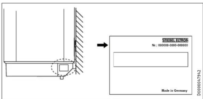
text_image
STIEBEL ELTRON Nr.: 000000-0000-000000 Made in Germany D0000047942INSTALLATION
7. Safety
Only a qualified contractor should carry out installation, commissioning, maintenance and repair of the appliance.
7.1 General safety instructions
We guarantee trouble-free operation and operational reliability only if the original accessories and spare parts intended for the appliance are used.
7.2 Regulations, standards and instructions

Note
Observe all applicable national and regional regulations and instructions.
7.3 Water installation
Cold water line
Galvanised steel, stainless steel, copper and plastic are approved materials.
A safety valve is required.
DHW line
Stainless steel, copper and plastic pipework are approved materials.

Material damage
When using plastic pipework, observe chapter "Specification / Fault conditions".
For sealed unvented operation, operate the appliance only with pressure-tested taps.
For open vented operation, the appliance must be operated with unpressurised taps.
8. Appliance description
8.1 Standard delivery
Delivered with the appliance:
- Mounting bracket (2 pce for 120 l and 150 l appliances)
- 5 mm spacers (2 pce for above, 2 pce for below)
- Caps
8.2 Accessories
The relay conversion set (part number 255789) enables an additional off-peak tariff/peak tariff isolator at the appliance electrical connection (see chapter "Specification / Wiring diagrams and connections").
Sealed unvented (pressure-tested) operation
Various safety assemblies are available for sealed unvented (pressure-tested) operation, depending on the static pressure. These type-tested safety assemblies protect the appliance against unacceptable excess pressure.
Pressure-tested taps are available as accessories.
Open vented (non-pressurised) operation
Non-pressurised fittings are available as accessories.
9. Preparations
9.1 Installation site
The appliance is exclusively designed for installation on a solid wall. Ensure the wall offers adequate load bearing capacity.
Always install the appliance vertically in a room free from the risk of frost and near the draw-off point.
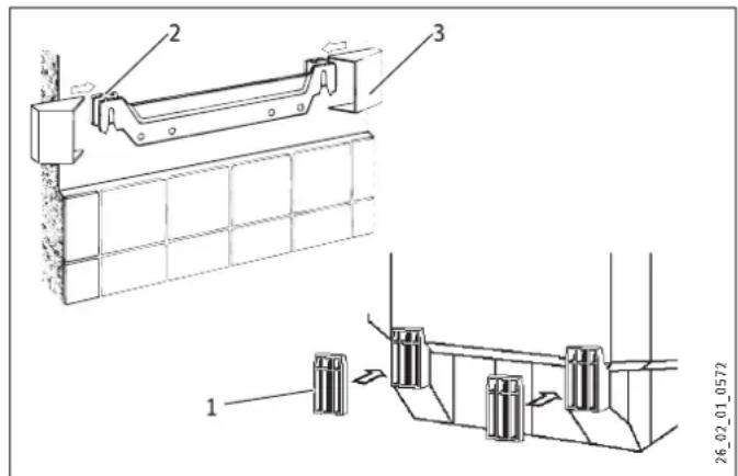
9.2 Mounting bracket
▶ Transfer the dimensions for the mounting bracket onto the wall.
▶ Drill the holes and secure the mounting bracket with screws and rawl plugs. Select fixing materials in accordance with the wall construction/condition.
2 mounting brackets are required for appliance types with 120 or 150 litres nominal capacity.
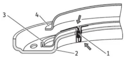
text_image
Technical diagram showing structural components and assembly of a panel or enclosure, labeled with numbers 1, 2, and 3.1 Lower spacer
2 Upper spacer
3 Cap
▶ Use the spacers supplied to compensate for any unevenness in the wall.
▶ Position the caps.
9.3 Power cable
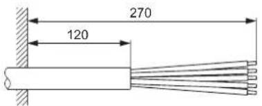
text_image
270 120D000042052
10. Preparing for installation
10.1 Water connection

Note
Carry out all water connection and installation work in accordance with regulations.
▶ Connect the hydraulic connections with flat gaskets.
Sealed unvented (pressure-tested) for supplying several draw-off points
▶ Fit the safety assembly in the cold water supply line. Be sure to choose the appropriate safety assembly, according to the static pressure.
▶ Observe the information in the safety assembly installation instructions.
Open (unpressurised) for the supply of one draw-off point

Note
Never shut off the outlet and pivoting spout. Do not use an aerator.
▶ Flush thoroughly.
▶ Use the open vented taps that we recommend.
10.2 Appliance installation
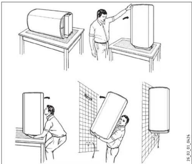
natural_image
Illustration of a person installing or adjusting a cylindrical device on a workbench, with no visible text or symbols.10.3 Power supply

WARNING Electrocution Carry out all electrical connection and installation work in accordance with relevant regulations.

WARNING Electrocution The connection to the power supply is only permissible as a permanent connection in conjunction with the removable cable grommet. The appliance must be able to be separated from the power supply by an isolator that disconnects all poles with at least 3 mm contact separation.

Material losses Install a residual current device (RCD).

Material damage Ensure that the appliance is earthed.
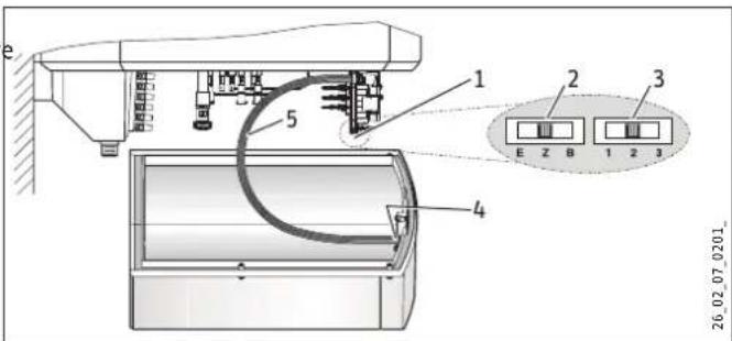
text_image
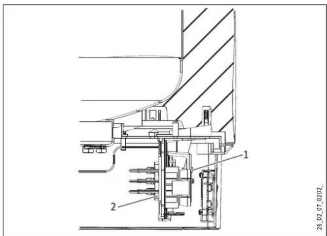
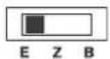
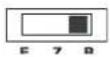
e 1 2 3 5 E Z B 1 2 3 4 26.02.07_0201_1 Electronic assembly, control unit
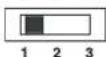
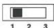
2 Operating mode switch
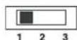
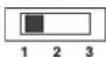
3 Output switch
4 Electronic assembly, operation
5 Connecting cable, electronic assemblies
▶ Undo the 4 screws.
▶ Remove the bottom cap.
▶ Pull out the cable grommet at the base while pressing the snap-in tabs.
▶ Push the cable grommet over the connecting cable and snap the cable grommet back in place.

Note
You can only change the output and operating mode when the power supply is isolated.
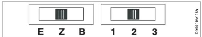
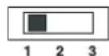
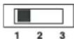
text_image
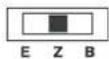
E Z B 1 2 3 D000040164E Single circuit operation
Z Dual circuit operation
B Manual rapid heat-up operation
1 Output 1
2 Output 2
3 Output 3

Note
For special circuits without external contactors for tariff changeover (dual circuit operation, dual meter measuring, 1/N/PE \~ 230 V), please see chapter "Specification / Wiring diagrams and connections".
▶ Select the output and operating mode with the switches on the control unit electronic assembly and select the required connection (see chapter "Specification / Wiring diagrams and connections").
- Tick the selected connected load and voltage on the type plate with a ballpoint pen.
▶ If required, connect a remote control for rapid heating to the mains terminal.
10.4 Completing installation
▶ Plug the 5-pole plug-in connection of the connecting cable onto the electronic assembly for operation, position X2.
▶ Position the bottom cap.
▶ Insert the 4 screws.
Sealed unvented (pressure-tested) operation:
▶ Connect the safety assembly with the appliance by securing the pipes to the appliance with screws.
Open vented (non-pressurised) operation
▶ Connect the appliance to the tap.
11. Commissioning
11.1 Commissioning
▶ Open the DHW valve until the appliance has filled up and the pipes are free of air.
▶ Observe the maximum permissible flow rate with a fully opened tap (see chapter "Specification / Data table").
▶ Sealed unvented (pressure-tested) operation:
[Non-Text]
[Non-Text]
[Non-Text]
[Non-Text]
[Non-Text]
If necessary reduce the flow rate at the butterfly valve of the safety assembly.
Fit the discharge pipe of the safety assembly with a constant slope.
Observe the information in the installation instructions of the safety assembly.
▶ Switch the mains power ON.
▶ Check the function of the appliance. If necessary, check the function of the rapid heater.
▶ Sealed unvented (pressure-tested) operation: Check the function of the safety assembly.
If an outlet temperature of 55 °C is achieved after commissioning, the temperature is automatically balanced and scale build-up detection is switched on. This interrupts heat-up for approx. 5 minutes.
11.1.1 Appliance handover
Explain the appliance function to users and familiarise them with its operation.
▶ Make users aware of potential dangers, especially the risk of scalding.
▶ Hand over these instructions.
11.2 Recommissioning
See chapter "Commissioning".
12. Settings
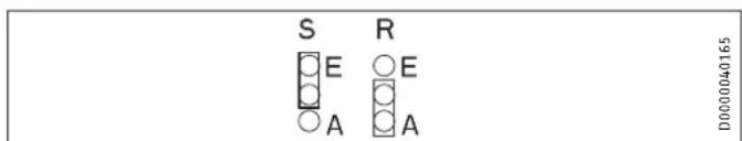
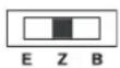
text_image
S E A R E A D0000040165(See also chapter "Specification / Wiring diagrams and connections").
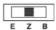
12.1 Switching on commercial mode
▶ To switch on commercial mode, replug the relevant jumper.
S Jumper ECO (energy saving mode)
E ECO on (factory setting)
A ECO off (commercial mode)
12.2 Switching on reverse control
▶ To switch on reverse control, replug the jumper.
R Reverse control jumper
E Reverse control on
A Reverse control off (factory setting)
13. Shutting down
▶ Disconnect the appliance from the mains at the MCB/fuse in the fuse box.
- Drain the appliance. See chapter "Maintenance / Draining the e appliance".
[Non-Text]
14. Troubleshooting

Note
The high limit safety cut-out can respond at temperatures below -15 °C. The appliance may be subjected to these temperatures during storage or transport.

Service code display
▶ Call up the service code display in the menu (see chapter "Settings / Menu settings").
The plugs are described in chapter "Specification / Wiring diagrams and connections".
1 Reset key, high limit safety cut-out
2 High limit safety cut-out
| Fault Code Cause Remedy | ||||
| No display. | There is no power. | Connect the power supply. | ||
| There is no connection to the electronic assembly for operation. | Check whether plug X2 is properly inserted. | |||
| The electronic assembly for operation is faulty. | Check the electronic assembly for operation and replace if required. | |||
| Scale build-up symbol "Ca" appears. | The flanged immersion heater is scaled up. | Descale the flanged immersion heater. The symbol is automatically reset. | ||
| Ca | ||||
| Service/fault symbol appears. | 2 | Permanent set temperature display. | The temperature sensor is faulty. | Check whether plug X10 is properly inserted. |
| 4 | Check the temperature sensor. | |||
| 16 | The impressed current anode is faulty. | Check whether plug X7 is properly inserted. Check the impressed current anode and wiring. | ||
| 128 | The set values selected last are active; possibly permanent display 128. | Communication between the electronic assemblies for control unit and operation is faulty. | Check whether plugs X2 are inserted properly in both assemblies. Check the assemblies and the connecting cable. | |
| Service/fault symbol flashes and the water does not heat up. | 6 | Permanent set temperature display. | The temperature sensor is faulty. | Check whether plug X10 is properly inserted. Check the temperature sensor. |
| 8 | The heat-up symbol does not appear. | The high limit safety cut-out has responded because the controller is faulty. | Remedy the cause of the fault. Replace the high limit safety cut-out. | |
| The high limit safety cut-out has responded because the temperature has dropped below -15 °C. | Press the reset button (see diagram). | |||
| The rapid heating does not switch on. | Check the key. | |||
| The flanged immersion heater is faulty. | Replace the flanged immersion heater. | |||
| 32 | Boil-dry protection. | There is no water in the water heater. | Fill the water heater. | |
| There is no anode current. | Check whether plug X7 is properly inserted. Check the impressed current anode and wiring. | |||
| The replaceable fine-wire fuse has tripped. | Check the replaceable fine-wire fuse. | |||
| 64 | The relay is faulty. | Replace the electronic assembly for the control unit. | ||
15. Maintenance

WARNING Electrocution
Before any work on the appliance, disconnect all poles of the appliance from the power supply.
For some maintenance work you must remove the bottom cap.
If you additionally need to drain the appliance, observe chapter "Draining the appliance".
Observe the immersion depth of the high limit safety cut-out (see chapter "Dimensions and connections").
15.1 Safety assembly
▶ Regularly check the safety assembly.
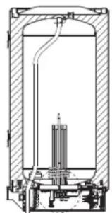
15.2 Draining the appliance

WARNING Burns
Hot water may escape during the draining process.
If the cylinder needs to be drained for maintenance or to protect the whole installation when there is a risk of frost, proceed as follows:
▶ Close the shut-off valve in the cold water line.
▶ Open the hot water taps on all draw-off points.
natural_image
Cross-sectional diagram of a cylindrical industrial vessel with internal components and piping (no text or labels)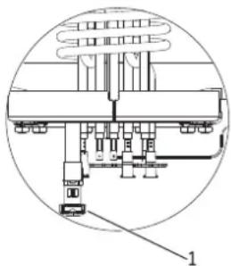
natural_image
Technical diagram of a mechanical assembly with labeled components (no readable text or symbols)26_02_07_0229_
1 Drain valve cap
▶ Undo the cap of the drain valve.
15.3 Descaling
▶ Only descale the flange after disassembly and never treat the cylinder surface and impressed current anode with descaling agents.
15.4 Anti-corrosion protection
▶ Ensure when carrying out service work that the anti-corrosion protection on the insulating plate is not damaged or removed.
▶ Reinsert the anti-corrosion protection correctly after replacement.
text_image
Technical diagram of a mechanical component with numbered parts labeled 1 to 4D000048051
1 Anti-corrosion protection
2 Pressure plate
3 Insulating plate
4 Copper flanged immersion heater
16. Specification
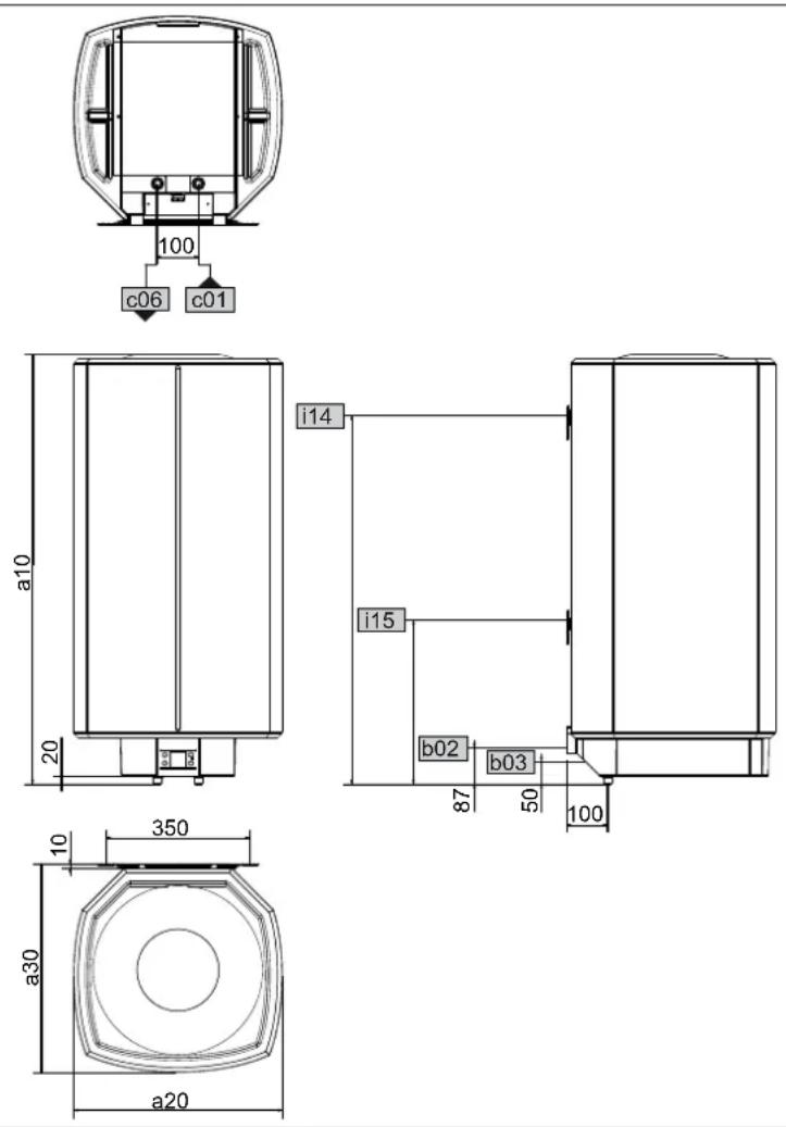
16.1 Dimensions and connections
D0000021508
| SHZ 30 LCD SHZ 50 LCD SHZ 80 LCD SHZ 100 | |||||||||
| LCD | SHZ 120 LCD | SHZ 150 LCD | |||||||
| a10 | Appliance | Height | mm | 770 | 740 | 1050 | 1050 | 1210 | 1445 |
| a20 | Appliance | Width | mm | 410 | 510 | 510 | 510 | 510 | 510 |
| a30 | Appliance | Depth | mm | 420 | 510 | 510 | 510 | 510 | 510 |
| b02 | Entry cables I | ||||||||
| b03 | Entry cables II | ||||||||
| c01 | Cold water inlet | Male thread | G 1/2 A | G 1/2 A | G 1/2 A | G 1/2 A | G 1/2 A | G 1/2 A | |
| c06 | DHW outlet | Male thread | G 1/2 A | G 1/2 A | G 1/2 A | G 1/2 A | G 1/2 A | G 1/2 A | |
| i14 | Wall mounting bracket I | Height | mm | 700 | 600 | 900 | 900 | 900 | 1100 |
| Max. ∅ fixing screw | mm | 12 | 12 | 12 | 12 | 12 | 12 | ||
| i15 | Wall mounting bracket II | Height | mm | 300 | 300 | ||||
| Max. ∅ fixing screw | mm | 12 | 12 | ||||||
16.1.1 High limit safety cut-out immersion depth
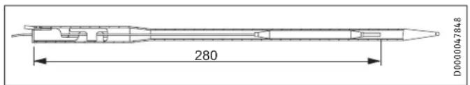
text_image
280 D00004784816.2 Wiring diagrams and connections
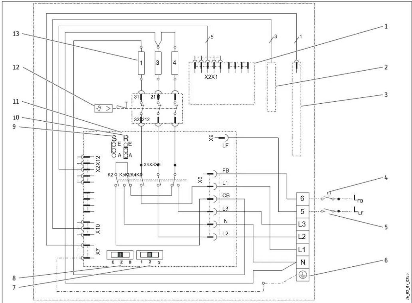
text_image
13 12 11 10 9 X2X12 X2X12 K2 K5K2K4K9 X4X8X6 X9 LF X6 FB L1 CB L3 N L2 6 5 L3 L2 L1 N 6 4 LFB LLF 5 6 8 7 E Z B 1 2 3 26.02.07_02551 Electronic assembly, operation
2 Temperature sensors
3 Impressed current anode
4 Remote control for rapid heating (any phase can be connected, no output transfer)
5 Power supply utility contact (any phase can be connected, no output transfer)
6 Mains terminal
7 Output switch
8 Operating mode switch
9 Jumper ECO (energy saving mode)
10 Reverse control jumper
11 Electronic assembly, control unit
12 High limit safety cut-out
13 Heating element, 2 kW \~ 230 V each
16.2.1 Dual circuit operation – Single meter measurement with power supply utility contact
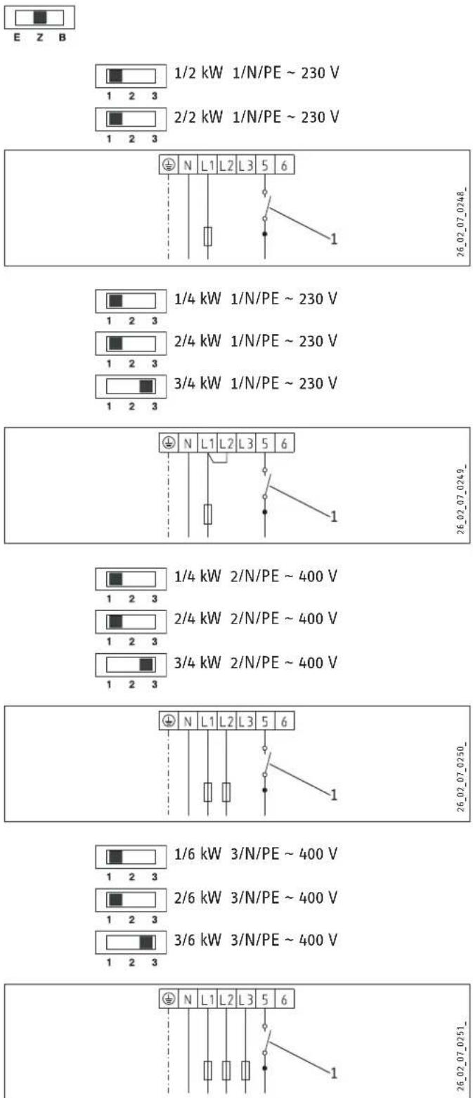
1/2 kW 1/N/PE \~ 230 V
2/2 kW 1/N/PE \~ 230 V
1/4 kW 1/N/PE \~ 230 V
2/4 kW 1/N/PE \~ 230 V
3/4 kW 1/N/PE \~ 230 V
1/4 kW 2/N/PE \~ 400 V
2/4 kW 2/N/PE \~ 400 V
3/4 kW 2/N/PE \~ 400 V
1/6 kW 3/N/PE \~ 400 V
2/6 kW 3/N/PE \~ 400 V
3/6 kW 3/N/PE \~ 400 V
1 Power supply utility contact
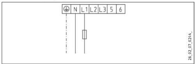
16.2.2 Single circuit and manual rapid heat-up operation
1 kW 1/N/PE \~ 230 V
2 kW 1/N/PE \~ 230 V
text_image
N L1 L2 L3 5 6 26.02.07.0244_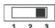
3 kW 1/N/PE \~ 230 V
4 kW 1/N/PE \~ 230 V
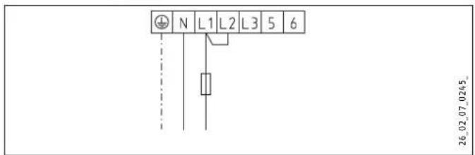
text_image
N L1 L2 L3 5 6 26_02_07_0245_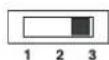
3 kW 2/N/PE \~ 400 V
4 kW 2/N/PE \~ 400 V
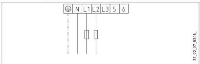
text_image
N L1 L2 L3 5 6 26.02.07.0246_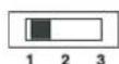
6 kW 3/N/PE \~ 400 V
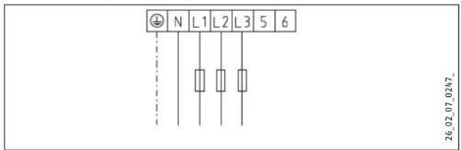
text_image
N L1 L2 L3 5 6 26_02_07_0247_16.2.3 Dual circuit operation - Dual meter measurement with power supply utility contact, single phase
1/N/PE \~ 230 V
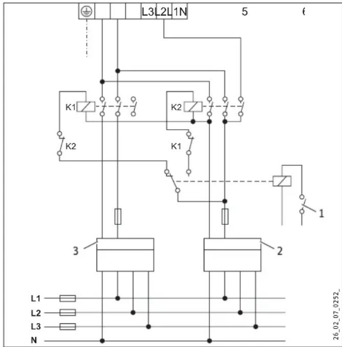
text_image
L3 L2 L1 N 5 6 K1 K2 K2 K1 3 2 1 L1 L2 L3 N 26.02.07_0252_1 Power supply utility contact
2 Off-peak tariff
3 Peak tariff
Special circuit without external contactors for tariff changeover

Note
If there are no external contactors for tariff changeover, the output is billed using the peak tariff meter even during the off-peak tariff period.
1/N/PE \~ 230 V
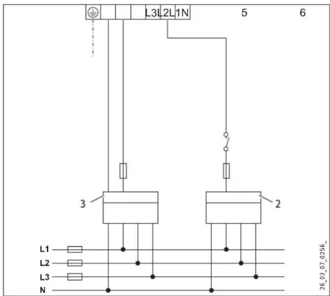
text_image
L3L2L1N 5 6 3 2 L1 L2 L3 N 26.02.07.0256_2 Off-peak tariff
3 Peak tariff
If it is not possible to extend the electrical installation with the relevant contactors, it is essential to install an additional off-peak/peak isolator at the appliance electrical connection (“Relay conversion set” see chapter “Appliance description / Accessories”).
Conversion measure, connection version 1:

Note
Setting 3 is not permissible at the output switch.
1/2 kW 1/N/PE \~ 230 V

2/2 kW 1/N/PE \~ 230 V
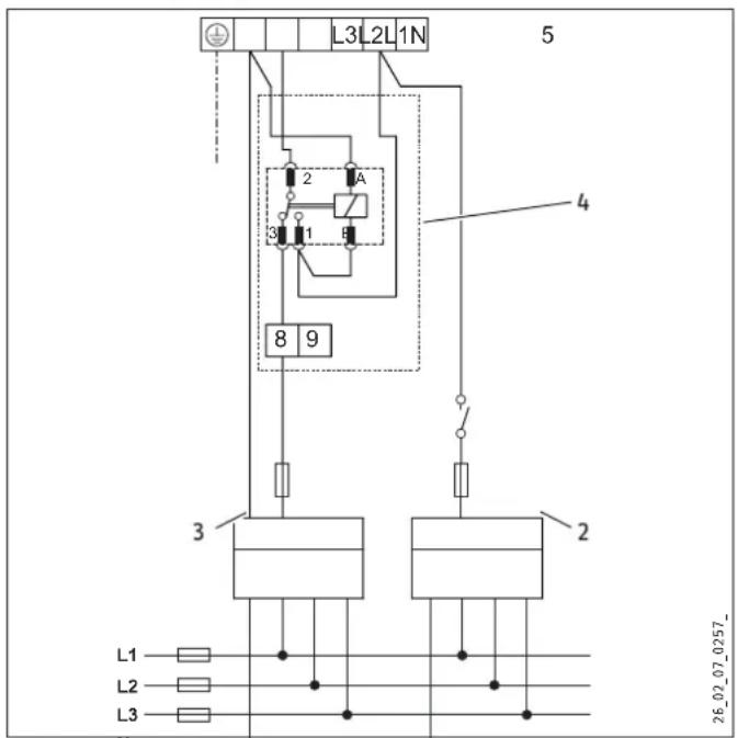
text_image
L3 L2 L1 N 5 2 A 3 1 B 8 9 4 3 2 L1 L2 L3 26.02.07.0257_2 Off-peak tariff
3 Peak tariff
4 "Relay conversion set" accessory (see chapter "Appliance description / Accessories")
Conversion measure, connection version 2:

Note
Setting 3 is not permissible at the output switch.
1/4 kW 1/N/PE \~ 230 V
2/4 kW 1/N/PE \~ 230 V
text_image
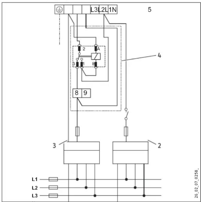
L3 L2 L1N 5 2 A 3 E 8 9 4 3 2 L1 L2 L3 26.02.07 0258_2 Off-peak tariff
3 Peak tariff
4 "Relay conversion set" accessory (see chapter "Appliance description / Accessories")
▶ Insert jumper 8-L2. During the off-peak tariff enable time, rapid heating is billed using a mixture of the peak and off-peak tariffs.
16.2.4 Dual circuit operation – Dual meter measurement with power supply utility contact, multiple phases
1/N/PE \~ 230 V
2/N/PE \~ 400 V
text_image
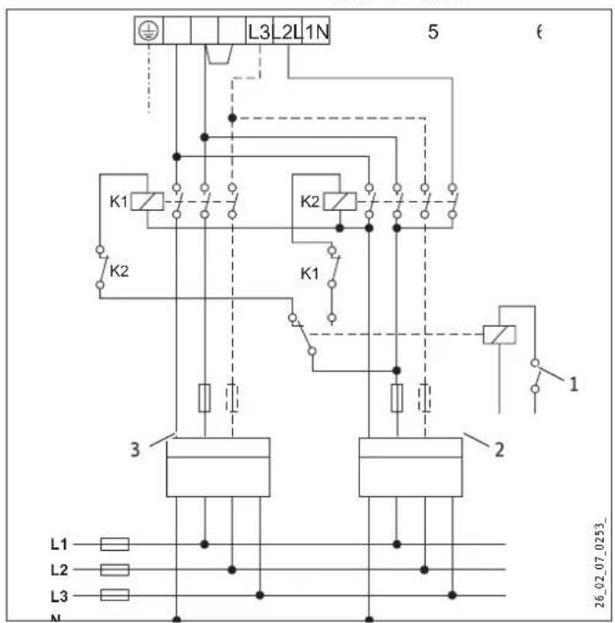
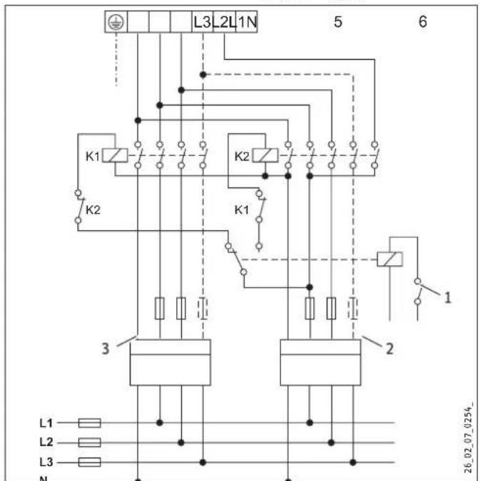
L3 L2 L1 N 5 K1 K2 K2 K1 3 2 L1 L2 L3 N 1 26_02_07_0253_2/N/PE \~ 400 V
3/N/PE \~ 400 V
text_image
L3 L2 L1 N 5 6 K1 K2 K2 K1 3 2 1 L1 L2 L3 N 26.02.07.0254_1 Power supply utility contact
2 Off-peak tariff
3 Peak tariff
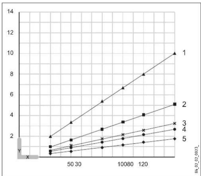
16.3 Heat up diagrams
The heat-up time depends on the cylinder capacity, cold water inlet temperature and heating output.
Diagrams refer to 15 °C cold water inlet temperature:
Set temperature setting 65 °C
line
| X-Axis | Series 1 | Series 2 | Series 3 | Series 4 | Series 5 | |---|---|---|---|---|---| | 0 | 2 | 1 | 1 | 1 | 1 | | 50 | 3.5 | 1.8 | 1.2 | 1.0 | 0.8 | | 100 | 5.5 | 2.8 | 1.8 | 1.6 | 1.2 | | 120 | 8 | 4 | 2.5 | 2.2 | 1.6 | | 140 | 10 | 5 | 3.2 | 2.8 | 1.9 |Set temperature setting 85 °C
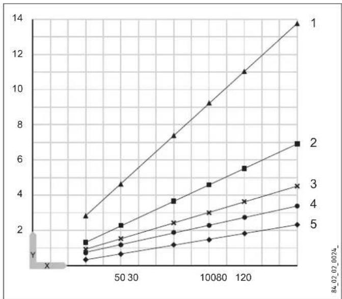
line
| X | Series 1 | Series 2 | Series 3 | Series 4 | Series 5 | |---|---|---|---|---|---| | 0 | 2.8 | 1.4 | 1.0 | 0.8 | 0.6 | | 50 | 4.6 | 2.3 | 1.6 | 1.4 | 1.0 | | 100 | 7.4 | 3.6 | 2.4 | 2.2 | 1.6 | | 10080 | 9.2 | 4.5 | 3.0 | 2.8 | 2.0 | | 120 | 11.0 | 5.5 | 3.6 | 3.4 | 2.4 | | 120 | 13.8 | 7.0 | 4.4 | 4.2 | 2.8 |X Nominal capacity in I
Y Duration in h
1 1 kW
2 2 kW
3 3 kW
4 4 kW
5 6 kW
16.4 Fault conditions
In the event of a fault, temperatures of up to 95 °C at 0.6 MPa can occur.
16.5 Details on energy consumption
Product data complies with EU regulations relating to the Directive on the ecodesign of energy related products (ErP).
| SHZ 30 LCD SHZ 50 LCD SHZ 80 LCD SHZ 100 LCD SHZ 120 LCD SHZ 150 LCD | |||||||
| 231251 | 231252 | 231253 | 231254 | 231255 | 231256 | ||
| Manufacturer | STIEBEL EL-TRON | STIEBEL EL-TRON | STIEBEL EL-TRON | STIEBEL EL-TRON | STIEBEL EL-TRON | STIEBEL EL-TRON | |
| Load profile | S | M | M | L | XL | XL | |
| Energy efficiency class | A | B | B | C | C | C | |
| Energy conversion efficiency | % | 38 | 40 | 40 | 39 | 38 | 40 |
| Annual power consumption | kWh | 489 | 1286 | 1223 | 2611 | 4382 | 4086 |
| Default temperature setting | °C | 85 | 85 | 85 | 85 | 85 | 85 |
| Sound power level | dB(A) | 15 | 15 | 15 | 15 | 15 | 15 |
| Option for exclusive operation during off-peak periods | - | - | - | - | - | - | |
| Smart function | X | X | X | X | - | X | |
| Weekly power consumption with Smart | kWh | 12,217 | 23,177 | 22,723 | 49,746 | 82,096 | |
| Weekly power consumption without Smart | kWh | 14,960 | 25,904 | 27,414 | 54,239 | 89,632 | |
| Daily power consumption | kWh | 2.773 | 6.548 | 6.618 | 13,042 | 20.219 | 20.161 |
| Cylinder capacity | l | 30 | 50 | 80 | 100 | 120 | 150 |
| Mixed water volume at 40 °C | l | 59 | 97 | 159 | 198 | 235 | 292 |
The information on energy conversion efficiency and annual power consumption applies only when intelligent control is switched on (Smart function).
16.6 Data table
| SHZ 30 LCD | SHZ 50 LCD | SHZ 80 LCD | SHZ 100 LCD | SHZ 120 LCD | SHZ 150 LCD | ||
| 231251 | 231252 | 231253 | 231254 | 231255 | 231256 | ||
| Hydraulic data | |||||||
| Nominal capacity | I | 30 | 50 | 80 | 100 | 120 | 150 |
| Mixed water volume 40 °C (15 °C/65 °C) | I | 59 | 97 | 159 | 198 | 235 | 292 |
| Electrical data | |||||||
| Connected load ~ 230 V | kW | 1-4 | 1-4 | 1-4 | 1-4 | 1-4 | 1-4 |
| Connected load ~ 400 V | kW | 1-6 | 1-6 | 1-6 | 1-6 | 1-6 | 1-6 |
| Phases | 1/N/PE, 2/N/PE, 3/N/PE | 1/N/PE, 2/N/PE, 3/N/PE | 1/N/PE, 2/N/PE, 3/N/PE | 1/N/PE, 2/N/PE, 3/N/PE | 1/N/PE, 2/N/PE, 3/N/PE | 1/N/PE, 2/N/PE, 3/N/PE | |
| Rated voltage | V | 230/400 | 230/400 | 230/400 | 230/400 | 230/400 | 230/400 |
| Frequency | Hz | 50-60 | 50-60 | 50-60 | 50-60 | 50-60 | 50-60 |
| Single circuit operating mode | X | X | X | X | X | X | |
| Dual circuit operating mode | X | X | X | X | X | X | |
| Manual rapid heat-up mode | X | X | X | X | X | X | |
| Application limits | |||||||
| Temperature setting range | °C | 20-85 | 20-85 | 20-85 | 20-85 | 20-85 | 20-85 |
| Max. permissible pressure | MPa | 0.6 | 0.6 | 0.6 | 0.6 | 0.6 | 0.6 |
| Test pressure | MPa | 0.78 | 0.78 | 0.78 | 0.78 | 0.78 | 0.78 |
| Max. permissible temperature | °C | 95 | 95 | 95 | 95 | 95 | 95 |
| Max. flow rate | l/min | 18 | 18 | 18 | 18 | 18 | 18 |
| Min./max. conductivity, drinking water | μS/cm | 100-1500 | 100-1500 | 100-1500 | 100-1500 | 100-1500 | 100-1500 |
| Energy data | |||||||
| Standby energy consumption/24 h at 65 °C | kWh | 0.46 | 0.54 | 0.67 | 0.86 | 0.99 | 1,16 |
| Energy efficiency class | A | B | B | C | C | C | |
| Versions | |||||||
| IP rating | IP25 | IP25 | IP25 | IP25 | IP25 | IP25 | |
| Sealed unvented type | X | X | X | X | X | X | |
| Open vented type | X | X | X | X | X | X | |
| Colour | White | White | White | White | White | White | |
| Dimensions | |||||||
| Height | mm | 770 | 740 | 1050 | 1050 | 1210 | 1445 |
| Width | mm | 410 | 510 | 510 | 510 | 510 | 510 |
| Depth | mm | 420 | 510 | 510 | 510 | 510 | 510 |
| Weights | |||||||
| Weight, full | kg | 53 | 78 | 118 | 140 | 165 | 203 |
| Weight, dry | kg | 22.9 | 27.6 | 37.6 | 39.5 | 42.4 | 52 |
Guarantee
The guarantee conditions of our German companies do not apply to appliances acquired outside of Germany. In countries where our subsidiaries sell our products a guarantee can only be issued by those subsidiaries. Such guarantee is only granted if the subsidiary has issued its own terms of guarantee. No other guarantee will be granted.
We shall not provide any guarantee for appliances acquired in countries where we have no subsidiary to sell our products. This will not affect warranties issued by any importers.
Environment and recycling
▶ Dispose of the appliances and materials after use in accordance with national regulations.
▶ If a crossed-out waste bin is pictured on the appliance, take the appliance to your local waste and recycling centre or nearest retail take-back point for reuse and recycling.
This document is made of recyclable paper.
- Dispose of the document at the end of the appliance's life cycle in accordance with national regulations.
REMARQUES PARTICULIÈRES
UTILISATION
text_image
Technical diagram showing structural components and assembly of a wall-mounted device, with numbered parts and a magnified view.natural_image
Illustration of a person installing or adjusting a large cylindrical device on a workbench, with no visible text or symbols.text_image
S E A R E A D0000040165natural_image
Cross-sectional diagram of a cylindrical industrial vessel or reactor with internal components and piping (no text or labels)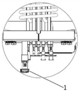
natural_image
Technical diagram of a mechanical assembly with labeled component 1 (no text or symbols present)26_02_07_0229
1 Capuchon de la vanne de vidange
text_image
Technical diagram of a mechanical component with numbered parts labeled 1 to 4D0000048051
text_image
L3L2L1N 5 6 3 2 L1 L2 L3 N 26_02_07_0256_line
| X | Series 1 | Series 2 | Series 3 | Series 4 | Series 5 | |---|---|---|---|---|---| | 30 | 2 | 1 | 1 | 1 | 1 | | 50120 | 3.5 | 1.7 | 1.3 | 1.2 | 0.8 | | 10080150 | 6.7 | 3.4 | 2.2 | 1.9 | 1.3 | | 15080200 | 8.0 | 4.2 | 2.7 | 2.4 | 1.6 | | 20080250 | 10.0 | 5.1 | 3.3 | 2.8 | 1.9 |line
| X-Axis | Series 1 | Series 2 | Series 3 | Series 4 | Series 5 | |---|---|---|---|---|---| | 30 | 2.8 | 1.4 | 1.0 | 0.8 | 0.6 | | 50120 | 4.6 | 2.3 | 1.6 | 1.3 | 0.9 | | 10080150 | 7.4 | 3.7 | 2.5 | 2.2 | 1.4 | | 15080200 | 11.0 | 5.6 | 3.6 | 3.2 | 1.9 | | 20080240 | 13.8 | 6.9 | 4.5 | 3.4 | 2.3 |X Contenance nominale en I
Y Durée en h
1 1 kW
2 2 kW
3 3 kW
4 4 kW
5 6 kW
16.4 Conditions de pannes
WAARSCHUWING Verbranding
4.3.2 Symbol Service/storing

Info
text_image
Technical diagram showing structural components and assembly of a wall-mounted device, with labeled parts 1, 2, and 3.natural_image
Illustration of a person installing or adjusting a large cylindrical device on a table, with no visible text or symbols.text_image
S E A R E A D0000040165text_image
Technical schematic diagram of a mechanical assembly with labeled components 1 and 226_02_07_0202
15. Onderhoud

natural_image
Technical line drawing of a mechanical assembly with cross-sectional and top views (no text or symbols)line
| X | Series 1 | Series 2 | Series 3 | Series 4 | Series 5 | |---|---|---|---|---|---| | 30 | 2 | 1 | 1 | 1 | 1 | | 50 | 3.5 | 1.5 | 1.2 | 1 | 0.8 | | 80 | 5.5 | 2.5 | 1.8 | 1.5 | 1 | | 100 | 6.7 | 3.5 | 2.2 | 2 | 1.2 | | 120 | 8 | 4.2 | 2.8 | 2.5 | 1.5 | | 150 | 10 | 5 | 3.5 | 3 | 1.8 |line
| X | Series 1 | Series 2 | Series 3 | Series 4 | Series 5 | |---|---|---|---|---|---| | 30 | 2.8 | 1.2 | 0.9 | 0.7 | 0.5 | | 50 | 4.6 | 2.2 | 1.4 | 1.1 | 0.8 | | 80 | 7.3 | 3.6 | 2.3 | 1.8 | 1.2 | | 100 | 9.1 | 4.5 | 2.9 | 2.3 | 1.5 | | 120 | 11.0 | 5.5 | 3.5 | 2.7 | 1.9 | | 150 | 13.8 | 6.9 | 4.4 | 3.3 | 2.3 |X Nominale inhoud in I
Y Duur in uur
1 1 kW
2 2 kW
3 3 kW
4 4 kW
5 6 kW