
RKFA100 - Vacuum Cleaner GRE - Free user manual and instructions
Find the device manual for free RKFA100 GRE in PDF.

| Product type | Automatic pool cleaner |
| Brand | GRE |
| Model | RKFA100 |
| Power supply | Low-voltage transformer (100-240 V AC / 50-60 Hz) |
| Electrical protection | Residual current device (RCD) ≤ 30 mA |
| Operating temperature | 13 °C to 35 °C |
| Storage temperature | 10 °C to 40 °C |
| Filtration type | Filter bag |
| Filter maintenance | Cleaning after each cycle |
| Impeller maintenance | Monthly cleaning |
| Brushes | Scrubbing brushes (replaceable) |
| Drive tracks | Rubber tracks (regular check) |
| Power cable | Floating cable, waterproof connector |
| Motors | Pump motor and drive motor |
| Features | Automatic cleaning cycle, suction, scrubbing |
| Safety | Do not use in presence of swimmers; automatic shut-off after cycle |
| Included accessories | Transformer, cable, handle, trolley (optional) |
| Use | Pool only, submerged |
| Warranty | Not specified (subject to storage temperature conditions) |
Frequently Asked Questions - RKFA100 GRE
User questions about RKFA100 GRE
0 question about this device. Answer the ones you know or ask your own.
Ask a new question about this device
Download the instructions for your Vacuum Cleaner in PDF format for free! Find your manual RKFA100 - GRE and take your electronic device back in hand. On this page are published all the documents necessary for the use of your device. RKFA100 by GRE.
USER MANUAL RKFA100 GRE
Operating Instructions
English ② Operating Instructions
Français ⑧ Mise en marche de votre robot nettoyeur de piscine
Deutsch 14 Bedienungsanleitung für den automatischen Bodensauger
Italiano 20 Funzionamento del nuovo robot di pulizia per piscine
Español 26 Manejo de Limpiafondos de Piscina
Português 32 Manual de instruções
Nederlands 38 Bedieningsinstructies
natural_image
Line drawing of a portable robotic device with handle and buttons, enclosed in a circular frame (no text or symbols)BK0017000 / PA -
natural_image
Line drawing of a mechanical device inside a circular frame (no text or symbols)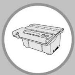
natural_image
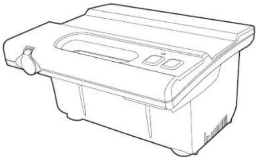
Simple line drawing of a plastic waste bin with a circular frame (no text or symbols)TOP ACCESS
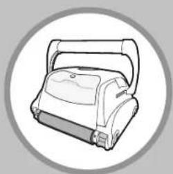
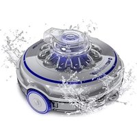
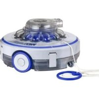
Robotic Pool Cleaner
CAUTION: Do not plug the power supply into a grounded outlet or do not switch the pool cleaner "ON" if it is not fully immersed in water. Operating the cleaner out of water will cause severe damage immediately and will result in loss of warranty.
Allow the cleaner to remain in the pool for 15 to 20 minutes following the end of its cleaning cycle. This will allow the motors to cool adequately. Do not leave the cleaner in the pool all the time. Always remember to turn the power supply "OFF" and unplug it from the power outlet before removing the cleaner from the pool.
WARNING: The cleaner must not be used when people are in the water. For use with swimming pool only
Safety Note
- The unit must be supplied through a residual current device (RCD) having a rated residual operating current not exceeding 30 mA
- The connection to the branch circuit should be consistent with the local and national wiring rules (electrical code).
- Mishandling of the unit can result in leakage of lubricants.
- If the supply cord is damaged, it must be replaced by the manufacturer's service agent or a qualified and trained person in order to avoid hazards.

This appliance is not intended for use by persons (including children) with reduced physical, sensory or mental capabilities, or lack of experience and knowledge, unless they have been given supervision or instruction concerning use of the appliance by a person responsible for their safety. Children should be supervised to ensure that they do not play with the appliance.
WARNING: A Ground Fault Current Interrupter (GFCI-USA) or a Residual Current Device (RCD-EUROPE) must be installed to protect your electric outlet and prevent any possible electric shock.
SAVE THESE INSTRUCTIONS
Dear Customer,
Thank you for choosing our product to clean your pool. We hope that you will enjoy using your new robot to maintain your swimming pool for years to come. Before you begin to use your robot, please take a few minutes to carefully read these operating instructions.
Again, thank you for choosing our product.
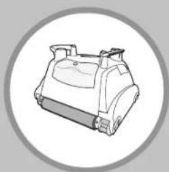
Components
While the appearance of your cleaner and some of its components may differ from those shown here, the function of the cleaner, operating procedures and maintenance practices are the same.

1) Handle
2) Outlet Top
3) Filter Lock Release
4) Filter Top Access
5) Handle Lock Mechanism
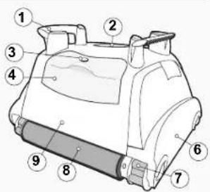
6) Side Plate
7) Drive Track
8) Scrubbing Brush
9) Unit Body
Your new automatic pool cleaner contains:
- The robotic pool cleaner with its floating cable.
- The Power Supply (transformer).
- Cart (optional)
Please read this manual completely before operating your pool cleaner.
Operating the pool cleaner
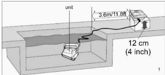
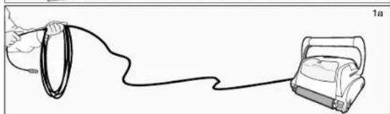
- Place the power supply (transformer) at least 3.6 meters / 11.8 feet from the pool and at least 12 cm / 4 inch above the surface (fig.1). The transformer will supply low voltage to the cleaner.
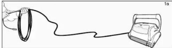
- Uncoil the cable.(fig.1a)

natural_image
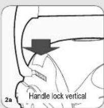
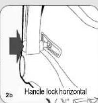
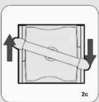
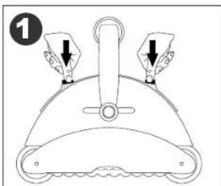
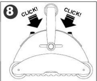
Line drawing of a hand holding a ring connected to a device labeled '1a' (no text or symbols on the diagram itself)- ONLY FOR MODELS WITH FLOATING HANDLE - For proper operation, lock the moveable handle diagonally across the top of the cleaner's body. Push down on the handle lock mechanism and slide the handle all the way to the end, then release the lock. Depending on your model, the handle lock button might be vertical or horizontal (fig.2a, 2b). The handle will remain fixed in this position. Repeat this process on the other side of the cleaner. Remember, the handle must be fixed diagonally (fig.2c)
natural_image
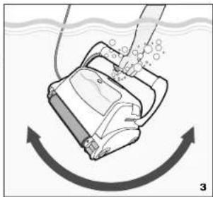
Diagram of a mechanical component with directional arrows indicating movement (no text or symbols)Place the unit in the water. Turn the unit side to side in the water to allow air to escape from the body and then let the cleaner sink to the bottom of the pool (fig.3). Then, spread the cable over the surface of the pool as evenly as possible (fig.1).
natural_image
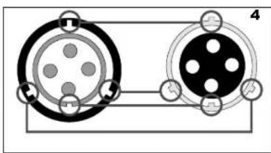
Diagram of a robotic device with motion arrows indicating flow or movement (no text or symbols)- Plug the cable into the power supply. Make sure the key on the plug exactly corresponds with the key slot on the socket of the power supply (fig.4). Plug the power supply into a grounded outlet. Ensure that the electric outlet has been properly grounded (fig.5). Press the "ON" button on the power supply. The light will glow indicating that the system is "ON" and the pool cleaner will start the cleaning cycle. The unit keeps record of the number of cleaning cycles. Only an authorized service center can display the accumulated cleaning cycles.
natural_image
Pure electrical circuit lines without any symbols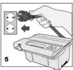
WARNING: A Ground Fault Current Interrupter (GFCI-USA) or a Residual Current Device (RCD-EUROPE) must be installed to protect your electric outlet and prevent any possible electric shock.
Operating the pool cleaner
natural_image
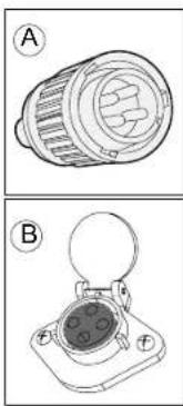
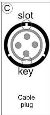
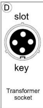
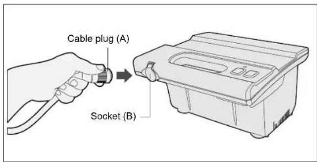
Technical line drawings of two electronic components (labeled A and B) with no visible text or symbolsTo plug the cable (Fig A) into the socket on the power supply (Fig. B), please do the following:
- Prepare the plug as seen in (Fig. C) with the key and 3 outside slots exactly as shown.
- Fit exactly the key and the slots from cable plug with the corresponding key and slots from the transformer socket. (Fig. D)
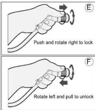
3.Push the plug into the socket of the transformer all the way in. - Once the plug is in, rotate the plug to the right to lock it into place (Fig.E).
- To remove the plug, first rotate the plug to the left to unlock it, then pull it out (Fig. F).
natural_image
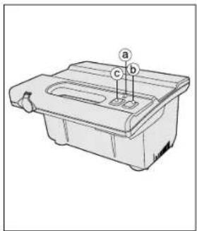
Technical line drawing of a mechanical component with labeled parts (a, b, c), no readable text or symbols present.a. Light indicates that the machine is running. b. Green push button turns the machine "ON". c. Red push button turns the machine "OFF".
IMPORTANT- After every cycle the pool cleaner will turn off automatically. In case you want to turn the machine off during the working cycle, push the red button once and the indicator light will turn off, indicating that the machine has stopped running.
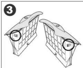
Maintenance and adjustment - Cleaning the filter
natural_image
Line drawing of a mechanical component with three arrows indicating force or movement (no text or symbols)
natural_image
Diagram of a mechanical component with arrows indicating direction (no text or symbols)
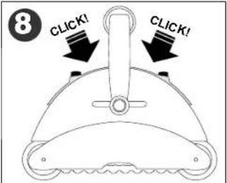
natural_image
Two identical mechanical components with circular end caps, shown side by side without any text or symbols.
natural_image
Diagram of a 3D structural component with grid pattern and directional arrows, no text or symbols present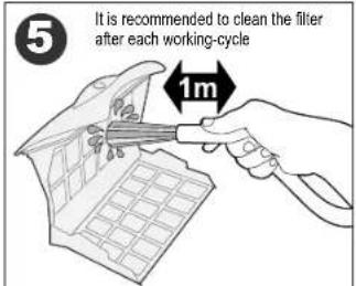
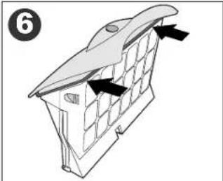
natural_image
Diagram of a roof structure with ventilation grilles and airflow arrows (no text or symbols)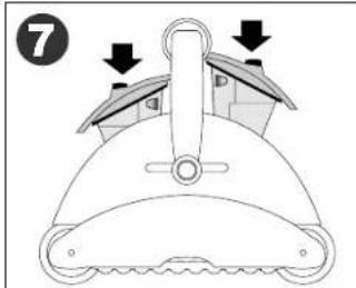
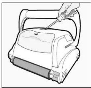
Maintenance and adjustment
Adjusting the suction valve:
In order to increase suction power, the valves located underneath your cleaner can be adjusted by pulling out the rim of the valve.
Before lowering the rim of the valve, make sure there is enough clearance and the unit movements won't be obstructed by any obstacles on the swimming pool floor or walls, such as (drains, steps, etc.)
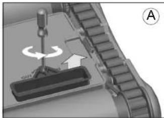
1) To pull out the rim rotate counterclockwise using a screwdriver (Fig. A)
2) To retract the rim rotate clockwise using a screwdriver (Fig. B)
natural_image
Mechanical assembly diagram showing a rotating component with an arrow indicating rotation direction (no text or symbols)
natural_image
Mechanical assembly diagram showing a rotating component with no visible text or symbolsCleaning the pump propeller:
1) Take out the screws from the outlet top
2) Take out the outlet top and remove hair and other debris around propeller
natural_image
Line drawing of a hand using a screwdriver to handle a vacuum cleaner (no text or symbols present)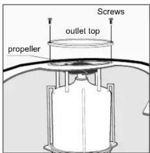
IMPORTANT TIPS:
- Shut off and unplug the power supply every time you remove the cleaner from the water.
• Clean the filter bag after every cycle.
• Periodically straighten out the floating cable. - Replace worn brushes to ensure maximum cleaning performance
Save your cleaner's packaging for off-season storage or for shipping the unit to your dealer if service is required. - Leave your pool cleaner in the water for 15 to 20 minutes after every cleaning cycle.
- Do not leave your cleaner in direct sunlight when not in use.
- Never leave the power supply in direct sunlight and avoid leaving it in the rain.
- Occasionally, you should rinse your cleaner in clean, fresh water. This will lengthen the service life of the drive belts, drive tracks and scrubbing brushes.
- Clean the propeller once a month
CLIMBING UNITS WITH FLOATING HANDLE ONLY
- If your unit has floating handle, reverse the diagonal position after every cleaning cycle to avoid tangling the cable.
- Make sure that your pool cleaner positions itself properly on the wall. The machine handle must rest parallel to the water line upon reaching the surface of the water.
IMPORTANT:
Please be sure to always keep your pool cleaner properly stored anywhere between 10 to 40 degrees Celsius (50 to 104 degrees Fahrenheit). This will keep the motors, plastics and seals protected. Failure to comply will result in loss of warranty. Robot can be used in water with temperatures ranging from 13^ to 35^ (55°F to 95^ ). However, the recommended optimal temperature is between 22^ and 32^ (72°F and 90^ )
IMPORTANT:
The transformer cord can only be replaced with the aid of special tools, normally available only to authorized dealers, distributors and service centers.
Troubleshooting Guide
PLEASE CHECK THE FOLLOWING BEFORE CALLING YOUR SERVICE CENTER
Before troubleshooting, the pool cleaner must be disconnected from the power supply and the power supply must be unplugged from the electrical outlet to prevent damage to the unit and possible personal injury.
- Unit does not pump water or move:
a) Check to see if electric outlet has power.
b) Check if transformer is plugged into a grounded outlet and the blue cable assembly is plugged into the transformer.*
c) Switch the power supply "OFF" and "ON" a few times. Allow 45 seconds between "ON" and "OFF".
d) Check for and remove any debris such as hair, string, or leaves that may be obstructing the free movement of the Drive Tracks.
- Unit does not pump water at all, or pumps slowly but moves:
a) Check to see if propeller is seized due to accumulation of hair or debris on the propellers. Remove the top screws on each outlet top and clean the propeller. When reassembling the top cover, do not overtighten the screws.
b) Check to see if the filter bags are thoroughly clean. Clean as necessary.
c) If a and b are negative, check the pump motors. If they are not functioning send the unit to your service center.
- Unit does not move but does pump water:
a) Check to see if forward/reverse motion is obstructed by foreign matter; hair, debris, etc. on drive tracks or there is an entanglement with the power cord.
b) Check for loose drive motor (3) connections.
c) If a, and b are negative, check the Master motor (and Slave motor if equipped) motors. If one or the other is not functioning, send the unit to your service center.
- Unit does not pick up dirt and debris:
a) Check 2a and 2b of this guide.
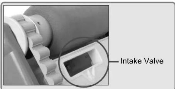
b) Check the Intake Valve Flaps on the underside of your unit (see image bellow). The Flaps should move freely to open and close. Clean and free the Valve Flaps if necessary.
c) Check the height of the intake rim. If necessary, adjust the height with a screw driver (for details see previous page)
*The transformer cord can only be replaced with the aid of special purpose tools normally available only to authorized dealers, distributors and service centers.
- Unit does not seem to cover the entire pool:
a) Most likely a thorough cleaning of the filter bags is needed.
b) Check to see that the floating cable is properly spread out and is untangled.
c) Allow the unit to run in the pool for the entire cleaning cycle.
d) Make sure that the Floating Handle (if equipped) is locked diagonally across the top of your unit's body.
e) Check that the Pump Motor is operating. Please refer to the section 2 of this guide
f) After following all of the above, if there is still a problem, call your dealer for specific additional assistance.
- Debris Comes Out Of The Unit When Removing It From Pool
(Top Access Lid Does Not Close Properly)
a) Lock Release - Check that the Lock release mechanism is not damaged. The lid edges should be aligned with the unit's body. Make sure the lid is engaged into the lock mechanism and snaps into place when inserted.
b) Intake Valves - Check that the intake valve flaps on the underside of your unit (see image bellow) move freely to open and close. Clean flaps if necessary.
FRANÇAIS
CONSIGNES DE SÉCURITÉ IMPORTANTES LIRE ET SUIVRE TOUTES LES INSTRUCTIONS
natural_image
Line drawing of a hand holding a ring connected to a device with a cable (no text or symbols)- UNIQUEMENT POUR LES MODÈLES EQUIPÉS DE POIGNÉE FLOTTANTE -
natural_image
Diagram of a mechanical or electrical component with directional arrows indicating movement (no text or symbols)natural_image
Diagram of a robotic vacuum cleaner with motion arrows indicating fluid flow (no text or symbols)natural_image
Pure electrical circuit lines without any symbols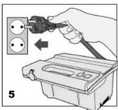
natural_image
Technical line drawings of two mechanical components labeled A and B, showing internal structures without any text or symbols.natural_image
Line drawing of a mechanical component with three arrows indicating force or movement (no text or symbols)
natural_image
Diagram of a mechanical component with arrows indicating direction (no text or symbols)
natural_image
Diagram of two identical brick wall-mounted units with circular components, no text or symbols present
natural_image
Diagram of a 3D structural component with grid pattern and directional arrows, no text or symbols present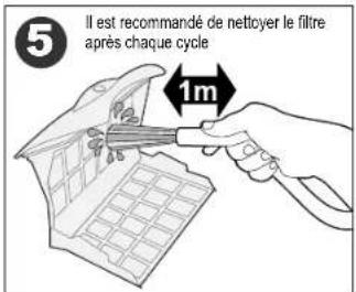
natural_image
Diagram of a roof structure with window panels and ventilation ducts, no text or symbols present

natural_image
Close-up of a mechanical component with a tool and directional arrow, no visible text or symbols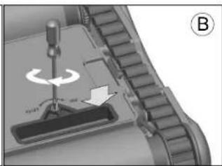
natural_image
Mechanical assembly diagram showing a tool interacting with a component, labeled with 'B' and directional arrows (no readable text or symbols)natural_image
Line drawing of a hand using a handheld vacuum cleaner to handle a cylindrical device (no text or symbols present)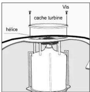
CONSEILS IMPORTANTS:
natural_image
Close-up of a mechanical component with a circular inset showing a small electronic device (no visible text or symbols)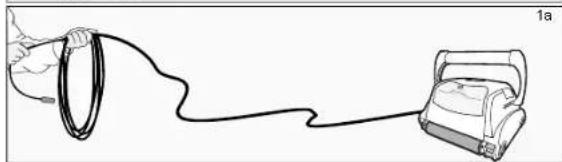
natural_image
Line drawing of a hand holding a ring connected to a device labeled '1a' (no text or symbols on the diagram itself)natural_image
Diagram of a mechanical or electrical component with directional arrows indicating movement (no text or symbols)natural_image
Diagram of a robotic device with motion arrows indicating flow or movement (no text or symbols)natural_image
Diagram of two circular connectors with pin symbols, connected by a cable (no text or labels)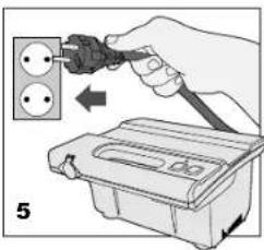
natural_image
Technical line drawings of two electronic components (labeled A and B) with no visible text or symbols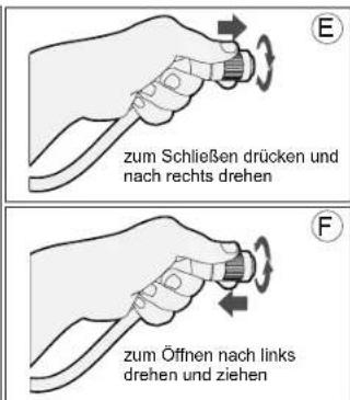
natural_image
Line drawing of a mechanical component with three directional arrows indicating force or movement (no text or symbols)
natural_image
Diagram of a mechanical component with arrows indicating direction (no text or symbols)
natural_image
Two identical brick wall-mounted objects with circular opening holes, shown in side view (no text or symbols)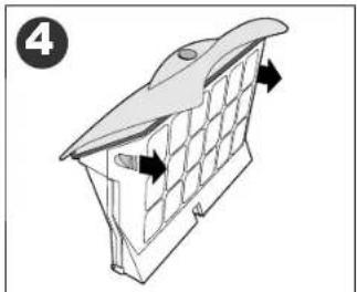
natural_image
Diagram of a 3D architectural structure with grid panels and directional arrows, no text or symbols present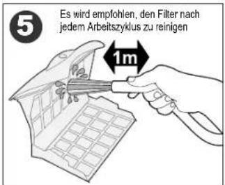
natural_image
Diagram of a roof structure with window panels and ventilation ducts, no text or symbols present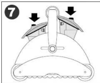

natural_image
Mechanical assembly diagram showing a rotating component with an arrow indicating rotation direction (no text or symbols)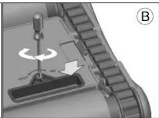
natural_image
Mechanical component diagram showing a rotating tool interacting with a base, labeled with 'B' and directional arrows (no text or symbols beyond labels)natural_image
Line drawing of a hand using a screwdriver to handle a vacuum cleaner (no text or symbols present)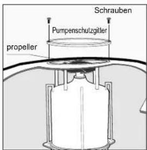
WICHTIGE HINWEISE:
natural_image
Close-up of a mechanical gear assembly with a magnified inset showing a rectangular component (no visible text or symbols)Einlassventil
ITALIANO
natural_image
Line drawing of a hand holding a ring connected to a device via a cable (no text or symbols)natural_image
Diagram of a robotic device with motion arrows indicating flow or movement (no text or symbols)natural_image
Diagram of two circular connectors with internal components and wiring, no text or symbols present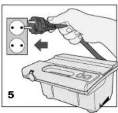
natural_image
Technical line drawings of two mechanical components labeled A and B, showing internal gear and housing (no text or symbols present)natural_image
Line drawing of a mechanical component with three arrows indicating force or movement (no text or symbols)
natural_image
Diagram of two identical brick wall-mounted units with circular components, no text or symbols present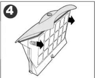
natural_image
Diagram of a 3D structural component with grid pattern and directional arrows, no text or symbols present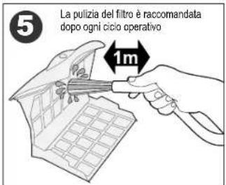
natural_image
Diagram of a building interior with window grilles and directional arrows indicating movement (no text or symbols)

natural_image
Mechanical assembly diagram showing a screwdriver pressing a component with an arrow indicating rotation (no text or symbols present)
natural_image
Mechanical component diagram showing a turning tool interacting with a base, labeled B (no text or symbols on the diagram itself)natural_image
Line drawing of a hand using a handheld vacuum cleaner to clean or install a machine (no text or symbols present)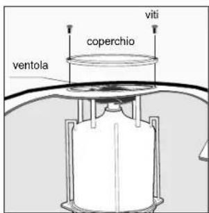
CONSIGLI IMPORTANTI:
natural_image
Close-up of a mechanical component with a circular inset showing a rectangular component (no visible text or symbols)Valvola d'ingresso
ESPAÑOL
natural_image
Line drawing of a hand holding a ring connected to a device labeled '1a' (no text or symbols on the diagram itself)natural_image
Pure diagram of a mechanical or electrical component with directional arrows, no text or symbols present.natural_image
Diagram of a robotic vacuum cleaner with motion arrows indicating flow (no text or symbols)natural_image
Diagram of two circular electrical connectors with pin holes and terminal blocks (no text or symbols)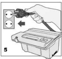
natural_image
Technical line drawings of two electronic components (labeled A and B) with no visible text or symbols.natural_image
Line drawing of a mechanical component with three arrows indicating force or movement (no text or symbols)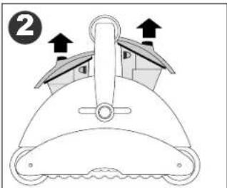
natural_image
Diagram of a mechanical component with arrows indicating direction (no text or symbols)
natural_image
Diagram of two identical brick wall-mounted units with circular components, no text or symbols present
natural_image
Diagram of a 3D structural component with grid pattern and directional arrows, no text or symbols present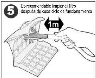
natural_image
Diagram of a roof structure with window grilles and directional arrows indicating airflow or movement (no text or symbols)
natural_image
Mechanical assembly diagram showing a screwdriver pressing a component with an arrow indicating rotation (no text or symbols present)
natural_image
Mechanical component diagram showing a turning tool interacting with a base, labeled B (no text or symbols on the diagram itself)natural_image
Line drawing of a hand using a screwdriver to handle a small cylindrical device (no text or symbols)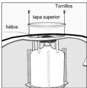
SUGERENCIAS ÚTILES:
natural_image
Close-up of a mechanical component with a magnified inset showing a small rectangular component (no visible text or symbols)Válvula de admisión
PORTUGUÊS
IMPORTANTES INSTRUÇÕES DE SEGURANÇA LEIA E SIGA TODAS AS INSTRUÇÕES
1) Alavanca
2) Tampo de salida
3) Desengate da trava do filtro
4) Acesso superior ao filtro
5) Mecanismo de trava da alavanca

natural_image
Line drawing of a hand holding a ring connected to a device via a cable (no text or symbols)natural_image
Diagram of a robotic device with motion arrows indicating flow or movement (no text or symbols)natural_image
Pure electrical circuit lines without any symbols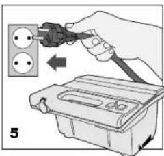
AVISO:
natural_image
Technical line drawings of two electronic components labeled A and B, showing internal structure and mounting base (no text or symbols present)Para ligar a ficha (Fig A) à tomada do transformador (Fig B), por favor faça o seguinte:
natural_image
Line drawing of a mechanical component with three arrows indicating force or movement (no text or symbols)

natural_image
Diagram of two identical brick wall-mounted units with circular components, no text or symbols present
natural_image
Diagram of a 3D architectural structure with grid panels and directional arrows, no text or symbols present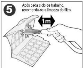
natural_image
Diagram of a building interior with window grilles and directional arrows indicating movement (no text or symbols)

natural_image
Mechanical assembly diagram showing a screwdriver pressing a component with an arrow indicating rotation (no text or symbols present)
natural_image
Mechanical component diagram showing a turning tool interacting with a base, labeled B (no text or symbols on the diagram itself)Limpeza da hélice da bomba:
natural_image
Line drawing of a hand using a screwdriver to handle a vacuum cleaner (no text or symbols present)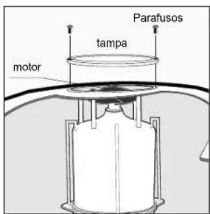
CONSELHOS IMPORTANTES:
natural_image
Close-up of a mechanical component with a magnified inset showing a rectangular component (no visible text or symbols)Válvula de admissão
NEDERLANDS
BELANGRIJKE VEILIGHEIDSINSTRUCTIES LEES EN VOLG ALLE INSTRUCTIES OP
natural_image
Line drawing of a hand holding a ring connected to a device labeled '1a' (no text or symbols on the diagram itself)natural_image
Diagram of a water purifier with flow arrows indicating circulation (no text or symbols)natural_image
Pure electrical circuit lines without any symbols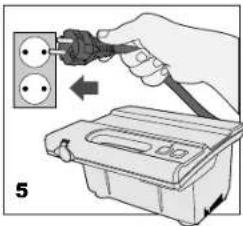
natural_image
Technical line drawings of two electronic components: a cylindrical connector and a socket socket (no text or symbols)a. Indicatielampje b. Groene knop = AAN c. Rode knop = UIT
natural_image
Line drawing of a mechanical component with three arrows indicating force or movement (no text or symbols)
natural_image
Diagram of a mechanical component with arrows indicating direction (no text or symbols)
natural_image
Diagram of two identical brick wall-mounted units with circular components, no text or symbols present
natural_image
Diagram of a 3D architectural structure with grid panels and directional arrows, no text or symbols present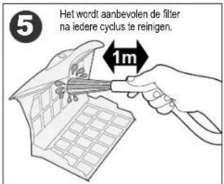
natural_image
Diagram of a roof structure with window grilles and directional arrows indicating airflow or movement (no text or symbols)

natural_image
Close-up of a mechanical component with a tool and directional arrow, no visible text or symbols
natural_image
Mechanical component diagram showing a turning tool interacting with a base, labeled B (no text or symbols on the diagram itself)natural_image
Line drawing of a hand using a screwdriver to handle a vacuum cleaner (no text or symbols)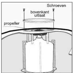
natural_image
Close-up of a mechanical component with a magnified inset showing a small rectangular component (no visible text or symbols)Inname klep
natural_image
Line drawing of a rectangular appliance with internal compartments and a handle (no text or symbols)Grounding
The power supply must be connected to a grounded 3 conductor socket. The mains power supply must be connected via a GFCI (ground fault circuit interrupter) or RCD (residual current device) having a rated residual operating current not greater than 30mA.
Fuse
The fuse must be changed by an authorized service agent or trained and qualified person only. For continued protection against risk of fire, replace only with the same type and rating of fuse.
Maintenance and safety
The cover should not be removed except by an authorized service agent or trained and qualified person. No internal adjustment or component replacement can be carried out by the user. The power cable must be disconnected before removing the cover.
If the power supply cord is damaged, it must be replaced by an authorized service agent or trained and qualified person. Do not operate the supply if the cord is damaged.
Environmental conditions
The power supply is designed to work both indoors and outdoors. However, the unit should not be operated in direct sunlight or be exposed to water. The power supply should not be operated in an ambient temperature in excess of 40^ C.
Erdung


- Operating Instructions
- TOP ACCESS
- Safety Note
- SAVE THESE INSTRUCTIONS
- Components
- Operating the pool cleaner
- Maintenance and adjustment - Cleaning the filter
- Maintenance and adjustment
- Adjusting the suction valve:
- Cleaning the pump propeller:
- IMPORTANT TIPS:
- CLIMBING UNITS WITH FLOATING HANDLE ONLY
- IMPORTANT:
- Troubleshooting Guide
- FRANÇAIS
- CONSIGNES DE SÉCURITÉ IMPORTANTES LIRE ET SUIVRE TOUTES LES INSTRUCTIONS
- CONSEILS IMPORTANTS:
- WICHTIGE HINWEISE:
- ITALIANO
- CONSIGLI IMPORTANTI:
- ESPAÑOL
- SUGERENCIAS ÚTILES:
- PORTUGUÊS
- IMPORTANTES INSTRUÇÕES DE SEGURANÇA LEIA E SIGA TODAS AS INSTRUÇÕES
- AVISO:
- Limpeza da hélice da bomba:
- CONSELHOS IMPORTANTES:
- NEDERLANDS
- BELANGRIJKE VEILIGHEIDSINSTRUCTIES LEES EN VOLG ALLE INSTRUCTIES OP
- Grounding
- Fuse
- Maintenance and safety
- Environmental conditions
- Erdung
Brand : GRE
Model : RKFA100
Category : Vacuum Cleaner