55020100 - Smart Home Niko - Free user manual and instructions
Find the device manual for free 55020100 Niko in PDF.
| Product type | Touch screen for smart home (Niko Home Control) |
| Brand | Niko |
| Model | 55020100 |
| Dimensions (H x W x D) | 140 x 200 x 22 mm |
| Screen size | 7 inches |
| Screen resolution | 800 x 480 pixels |
| Weight | 934 g (without dowels and screws) |
| Power supply | 24 Vdc (±10%) or Power over Ethernet (PoE) IEEE802.3af |
| Power consumption | 300 mA (24 Vdc) / 150 mA (PoE 48 Vdc) |
| Operating temperature | -5 °C to 40 °C |
| Storage and transport temperature | -10 °C to 65 °C |
| Network connection | Ethernet 10/100 Mbit/s (RJ45) |
| Maximum number of screens per installation | 10 (includes smartphone/PC apps) |
| Main functions | Control of Niko Home Control actions, consumption display (water, gas, electricity), favorites, settings, alarm log |
| Maintenance and cleaning | Soft dry or slightly damp cloth; do not use detergents |
| Mounting | On wall, on flush mounting box ≥40 mm depth, at eye level, away from sunlight and humidity |
| Reset | Reset button accessible with a paperclip (without disassembly) |
| Safety | Compliant with EN60950-1 + A11, CE marking; do not expose to direct sunlight or heat sources |
| Spare parts and repairability | Repair by authorized professional; accessible reset button |
| General information | Programming via Niko Home Control software; compatible up to 256 actions in 100 locations |
Frequently Asked Questions - 55020100 Niko
User questions about 55020100 Niko
0 question about this device. Answer the ones you know or ask your own.
Ask a new question about this device
Download the instructions for your Smart Home in PDF format for free! Find your manual 55020100 - Niko and take your electronic device back in hand. On this page are published all the documents necessary for the use of your device. 55020100 by Niko.
USER MANUAL 55020100 Niko
text_image
Min. 1,50m
natural_image
3D diagram of a device with labeled ports and connectors, showing internal components connected to a terminal (no text or symbols present)natural_image
Illustration of a computer monitor with a blue cover and red arrow indicating rotation (no text or symbols)natural_image
Diagram showing a 3D object with red arrows indicating flow or force, and a curved arrow labeled 'C' (no text or symbols present)text_image
Min. 1,50m
natural_image
3D diagram of a device with labeled ports and connectors, no readable text or symbols presentnatural_image
Illustration of a computer monitor with a blue cover and red arrow indicating rotation (no text or symbols)natural_image
3D diagram of a curved surface with red arrows indicating direction, and a vertical L-shaped element below (no text or symbols)text_image
Min. 1,50m
natural_image
3D diagram of a device with labeled ports and connectors, no readable text or symbols presentnatural_image
Illustration of a computer monitor with a blue stripe and black screen, showing a red curved arrow indicating rotation (no text or symbols)natural_image
3D diagram of a computer monitor with red arrows indicating flow or movement, and a scroll-like symbol at the bottom (no text or labels)Touchscreen programmieren

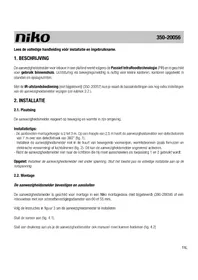
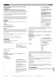
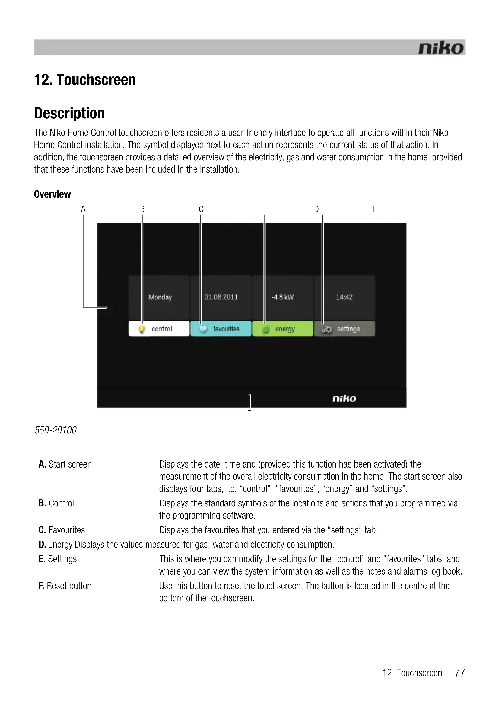
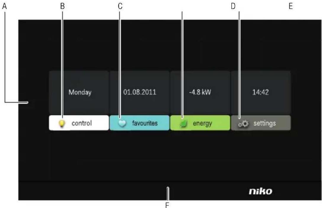
The Niko Home Control touchscreen offers residents a user-friendly interface to operate all functions within their Niko Home Control installation. The symbol displayed next to each action represents the current status of that action. In addition, the touchscreen provides a detailed overview of the electricity, gas and water consumption in the home, provided that these functions have been included in the installation.
Overview
text_image
A B C D E Monday 01.08.2011 -4.8 kW 14:42 control favourites energy settings niko F550-20100
A. Start screen
Displays the date, time and (provided this function has been activated) the measurement of the overall electricity consumption in the home. The start screen also displays four tabs, i.e. “control”, “favourites”, “energy” and “settings”.
B. Control
Displays the standard symbols of the locations and actions that you programmed via the programming software.
C. Favourites
Displays the favourites that you entered via the "settings" tab.
D. Energy Displays the values measured for gas, water and electricity consumption.
E. Settings
This is where you can modify the settings for the “control” and “favourites” tabs, and where you can view the system information as well as the notes and alarms log book.
F. Reset button
Use this button to reset the touchscreen. The button is located in the centre at the bottom of the touchscreen.
Operation
The symbols on the touchscreen are used by the resident to operate the functions that you assigned while programming the installation. The resident can also use the touchscreen to request more information about the electricity, gas and water consumption in the home.
Using the touchscreen
1 Touch the touchscreen. The start screen will appear.
If you do not touch the screen within 30 s, the display will be dimmed to reduce energy consumption.
2 Touch the corresponding tab to select "control", "favourites", "energy" or "settings".
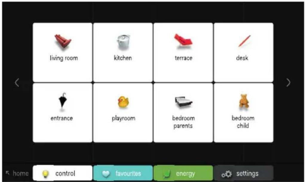
Using the "control" tab
1 Touch the "control" tab.
text_image
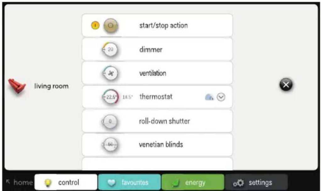
living room kitchen terrace desk entrance playroom bedroom parents bedroom child 5 home control favourites energy settings2 Select the location of your choice.
text_image
start/stop action dimmer ventilation 22.5° 18.5° thermostat roll-down shutter venetian blinds living room home control favourites energy settings3 Select the function you wish to activate or deactivate.
Using the "favourites" tab

To be able to use favourites, these favourites must have been entered first via the "settings" tab.
1 Touch the "favourites" tab.
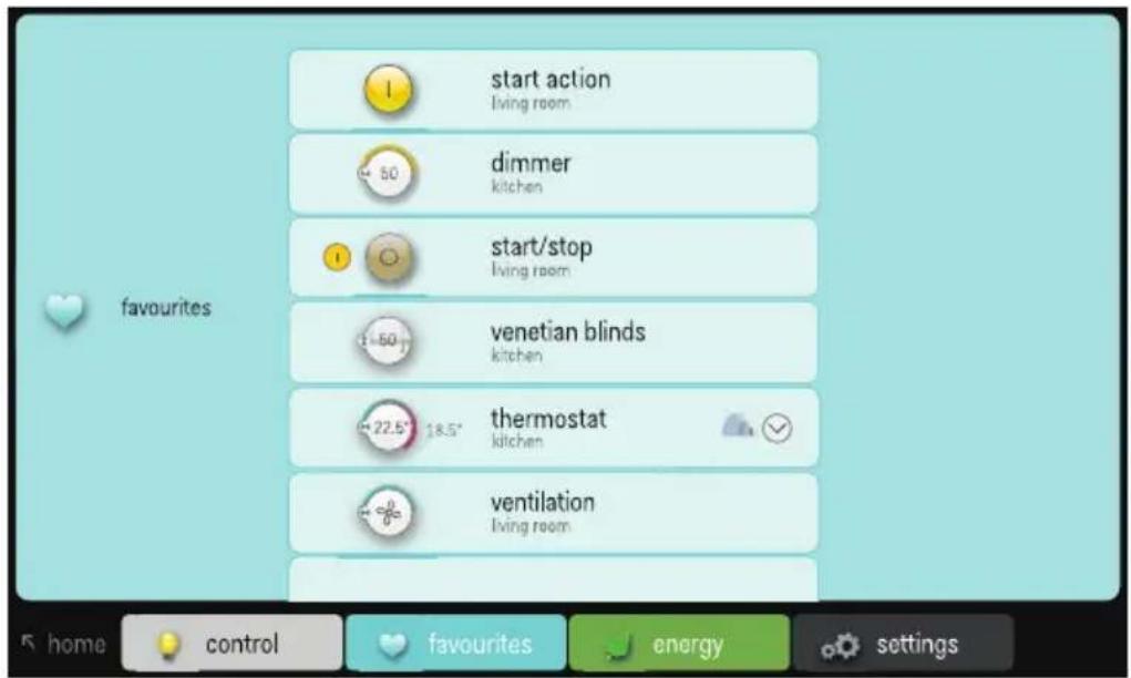
text_image
start action living room dimmer kitchen start/stop living room venetian blinds kitchen thermostat kitchen ventilation living room home control favourites energy settings2 Select the function you wish to control.
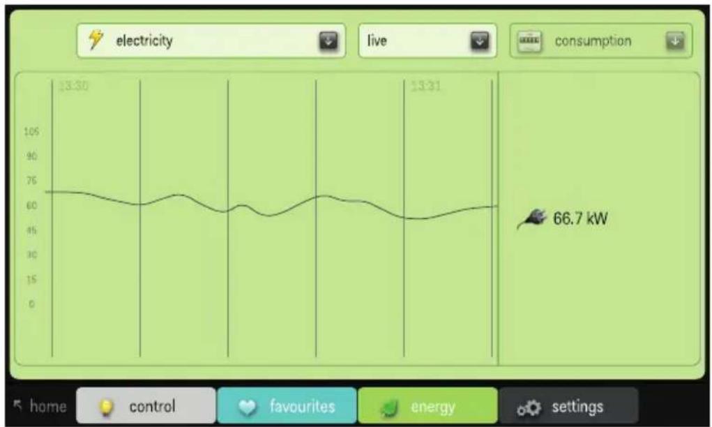
Using the "energy" tab

- The installation must be fitted with an IP interface (see IP interface on page 74) and an electricity measuring module (see Electricity measuring modules on page 58) or a pulse counter (see Pulse counter on page 70) to be able to display the measuring data for gas, water and electricity.
- If you are only using a pulse counter, live data for gas, water and electricity consumption will not be available.
1 Touch the "energy" tab.
line
| Time | Power (kW) | | ------ | ---------- | | 13:30 | 66.7 |2 Select the type of measuring data you wish to display: electricity, gas or water.
3 Select the period of your choice: live, day, week, month or year.
4 Select the display mode for the period you selected: consumption or cost.
Using the "settings" tab
1 Touch the "settings" tab.
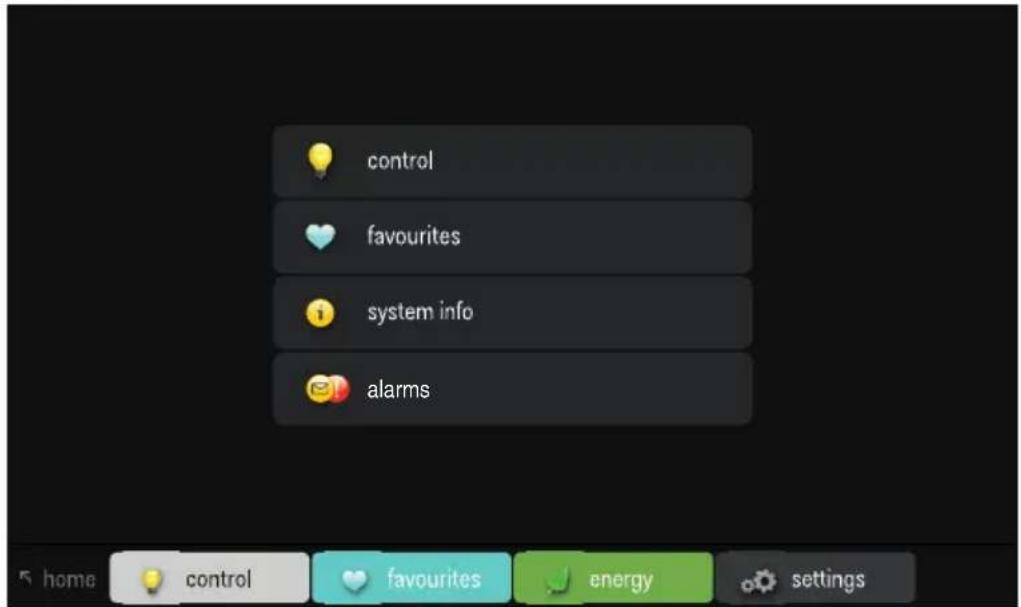
text_image
control favourites system info alarms2 Do one of the following:
- Select "control" to select different symbols for the various locations.
- Select "favourites" to add or remove actions from the list of favourites.
- Select "system info" to view the system information.
- Select "alarms" to view the notes and alarms log book.
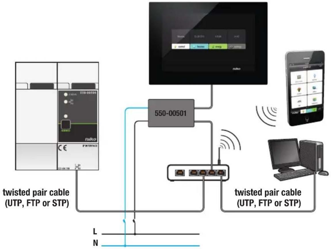
Installation

- The Niko Home Control installation must be fitted with an IP interface (see IP interface on page 74) to enable communication with the touchscreen. The touchscreen can be connected to the IP interface either directly or via the home network. Ensure that the touchscreen is on the same network as the IP interface.
- Use a twisted pair cable, such as a UTP, FTP or STP cable. Both the touchscreen and the IP interface have an RJ45 jack. You will need to mount RJ45 plugs onto the cable to be able to connect one end of the cable to the IP interface, and the other end to the touchscreen.
- The touchscreen can be supplied with power using Power over Ethernet (PoE) via the same twisted pair cable, for which you use the Niko PoE power supply (550-00501). Alternatively, you can provide a separate power supply cable, which you connect to a separate 24 Vdc power supply module in the electrical cabinet. In that case, you will need a 24 V power supply cable such as an SVV, JYSTY, TPVF or UTP cable in addition to the twisted pair cable.
Connection diagrams
flowchart
graph TD
    A["twisted pair cable (UTP, FTP or STP)"] --> B["550-00501"]
    B --> C["USB ports"]
    C --> D["Mobile Device"]
    D --> E["Computer"]
    F["niko"] --> G["USB port"]
    H["550-00501"] --> I["USB port"]
    J["twisted pair cable (UTP, FTP or STP)"] --> K["USB port"]
    L["L"] --> M["N"]
    N["N"] --> O["L"]
With Power over Ethernet (PoE)
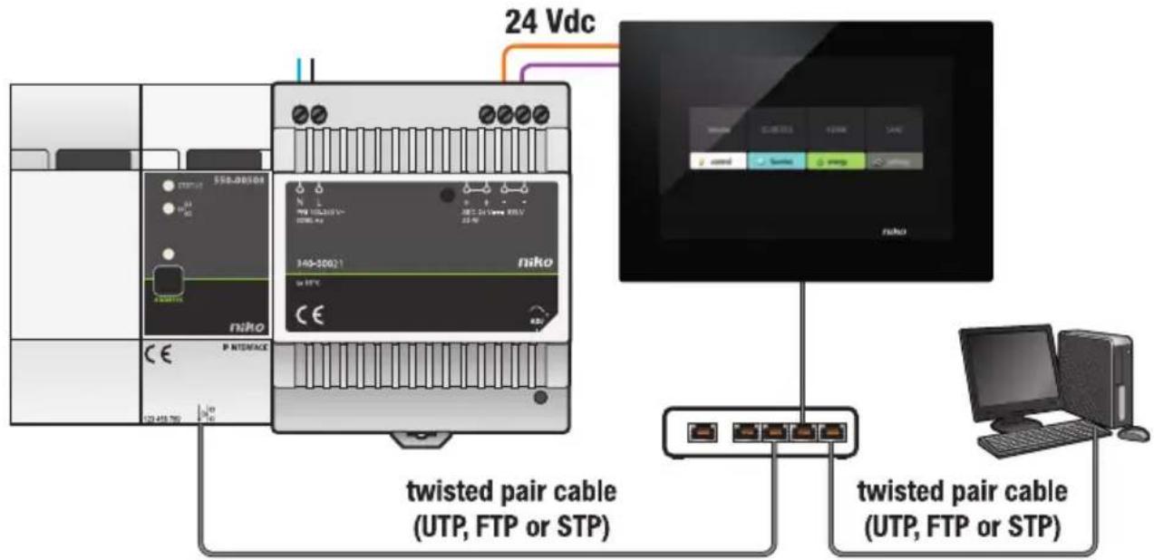
text_image
24 Vdc twisted pair cable (UTP, FTP or STP) twisted pair cable (UTP, FTP or STP)With 24V power
Take into account the dimensions of the installation bracket and the touchscreen in the images below to determine the exact location of the touchscreen on the wall.

Horizontally, the centre of the flush-mounting box must be at a distance of at least 130 mm from other walls, doors, etc.
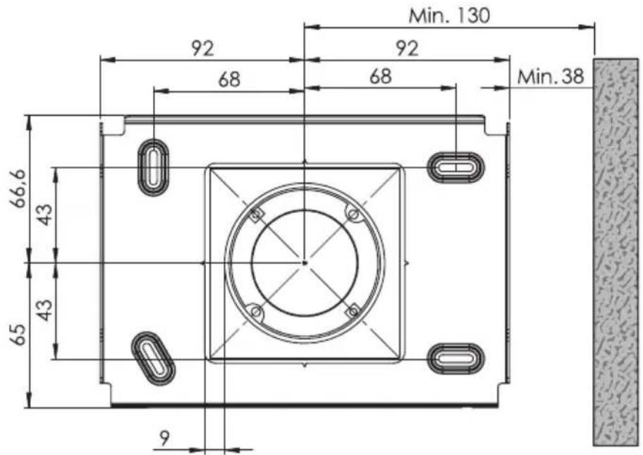
text_image
Min. 130 92 92 68 68 Min. 38 66,6 43 43 65 9Installation bracket dimensions
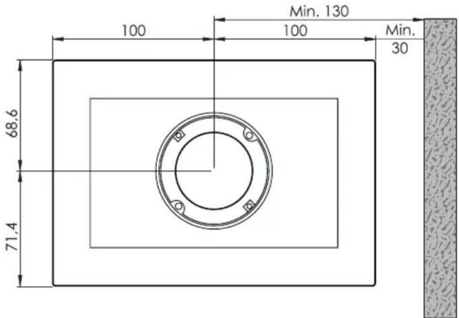
text_image
100 68.6 71.4 100 Min. 130 Min. 30Touchscreen dimensions

- Mount the touchscreen:
- at eye level for optimum visibility.
- Do NOT mount the touchscreen:
- in direct sunlight.
- within the immediate vicinity of a fireplace, heater, or any other heat-generating source.
- in damp locations.
- The touchscreen itself is not suitable for flush mounting. Mount the touchscreen onto the wall using a standard flush-mounting box with a depth of at least 40 mm.
- A total of ten touchscreens, smartphone or PC applications can be used per installation.
Use a drill (with a 6 mm diameter) to drill a hole of 40 mm for each plug. If you are drilling in timber, you will not need to use the plugs, and only a drill hole of 20 mm with a 3 mm diameter will be required.
Follow the steps below to mount the touchscreen:
1 Screw the assembly plate onto the wall using the four screws and plugs supplied.
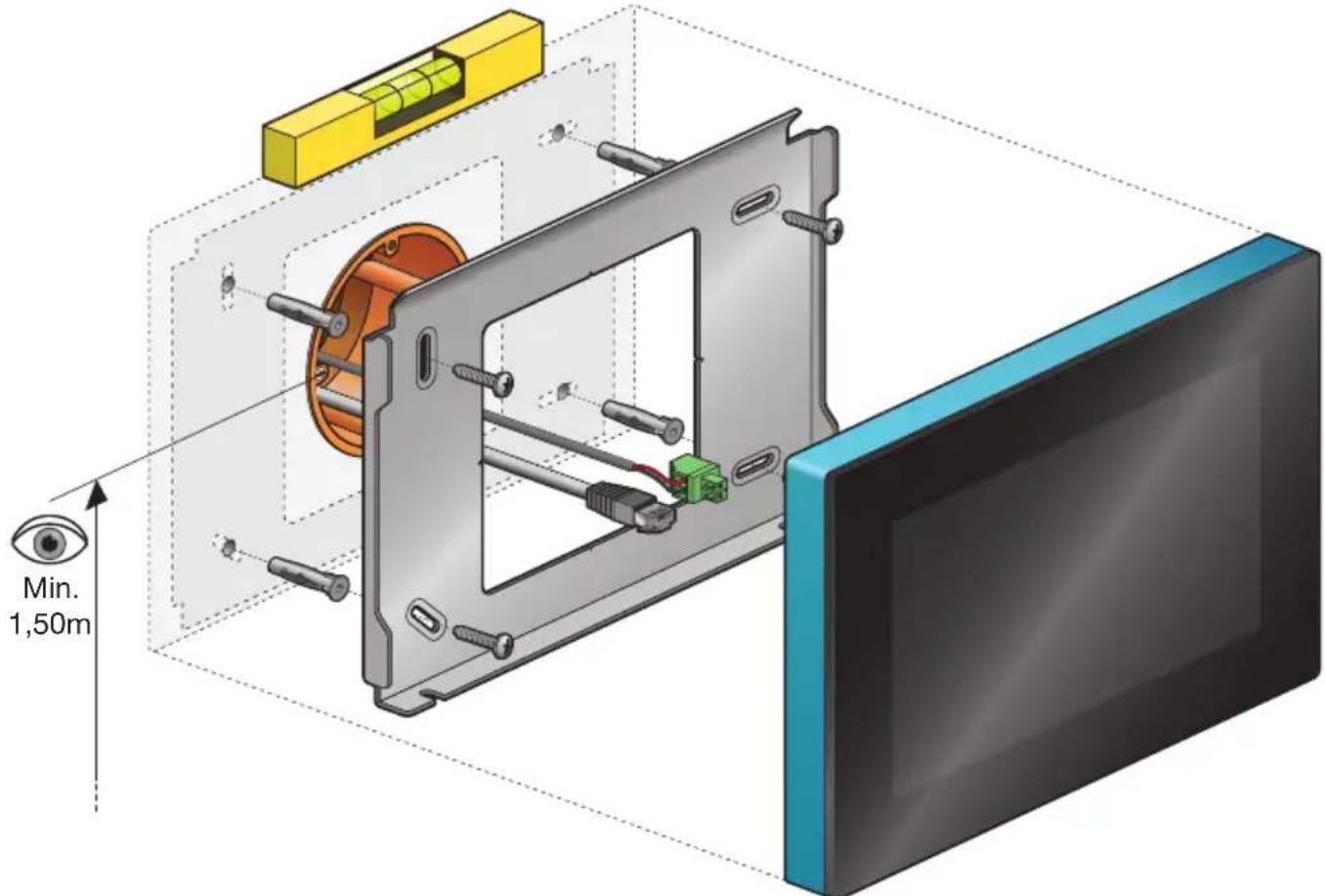
text_image
Min. 1,50m
- Mount the assembly plate in a central position on top of the flush-mounting box.
- Make sure the assembly plate is level.
- The unevenness of walls cannot exceed 2 mm.
2 Connect the green screw terminal supplied to the 24V power supply cable while observing the polarity as indicated on the back of the touchscreen.

- If you are using PoE, you do not need a separate 24V power supply cable.
- Only use the Niko PoE supply of type IEEE802.3af. This power supply provides voltage via the free pairs.
- The green screw terminal supplied (24V power supply) is suitable for a maximum copper diameter of maximum 1.5 mm ^4 .
3 Crimp an RJ45 plug onto the twisted pair cable (UTP, STP or FTP). Observe the standard colour coding for RJ45.
4 Connect the RJ45 plug and, if applicable, the 24V power supply cable, to the touchscreen.
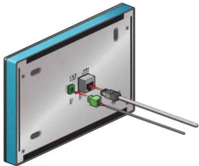
natural_image
3D diagram of a device with labeled ports and connectors, showing internal components connected to a rod (no text or symbols present)5 Hang the touchscreen onto the assembly plate and press it down against the wall in one smooth motion.
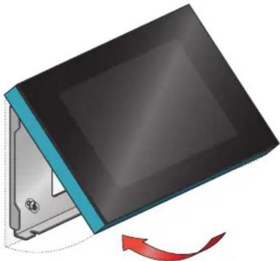
natural_image
Illustration of a computer monitor with a blue stripe and black screen, showing a red curved arrow indicating rotation (no text or symbols)6 Tighten the touchscreen using the hexagon key supplied and remove the protective foil.
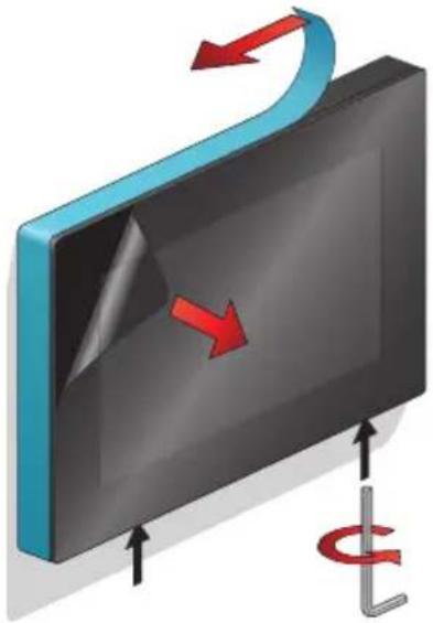
natural_image
3D diagram of a curved surface with red arrows indicating direction, and a vertical L-shaped element below (no text or symbols)Programming the touchscreen

- Add the touchscreen at the beginning of the project.
- The touchscreen can display a maximum of 256 actions across 100 locations.
- Several touchscreens used in one single installation cannot be programmed differently.
When you add the touchscreen to the project of the installation via the programming software, all pre-programmed actions will automatically be linked to the touchscreen.
The programming software allows you to create locations and link actions to each location. This will give you a better overview of the home. If an action is not linked to a location, the software will link the action to a virtual location. When all actions have been linked, click the touch icon to open the overview. In this overview, you can remove any actions that you do not want to be displayed on the touchscreen.
Touchscreen maintenance
Use a soft dry or slightly damp cloth to clean the touchscreen. Do not use detergents or other cleaning agents.
Troubleshooting
| Problem Possible cause Solution | ||
| Nothing is displayed on the screen. | Communication error | Check whether network communication is possible between the touchscreen and the IP interface. |
| You can’t operate the installation. Reset the touchscreen. | Use an unfolded paperclip to press the reset button. There is no need to disassemble the touchscreen. | |
Technical data
- power supply voltage: 24 Vdc (± 10%) (SVV, JYSTY, TPVF, UTP, etc.) or Power over Ethernet (PoE) (UTP, STP, FTP) (48 V)
• electricity consumption: 300 mA (24 Vdc) or 150 mA (PoE 48 Vdc) - ambient temperature:
- in use: -5 - 45^ C
- storage and transport: -10 - 65°C
- ethernet connection speed: 10 - 100 Mbit/s
• in conformity with EN60950-1 + A11 - CE marking
• dimensions: 140 x 200 x 22 mm (HxWxD) - screen size: 7"
• screen resolution: 800 x 480
• weight: 934 g (excluding plugs and screws)
text_image
Min. 1,50m
natural_image
3D diagram of a device with labeled ports and connectors, no readable text or symbols presentnatural_image
Illustration of a computer monitor with a blue cover and red arrow indicating rotation (no text or symbols)natural_image
3D diagram of a curved surface with red arrows indicating direction, and a vertical L-shaped element below (no text or symbols)text_image
Min. 1,50m