35020070 - Smart Home Niko - Free user manual and instructions
Find the device manual for free 35020070 Niko in PDF.
| Product type | 360° presence/absence detector (master) for flush mounting |
| Dimensions (visible) | 46.4 x 100 mm (HxW) |
| Dimensions (total) | 73.4 x 100 mm (HxW) |
| Supply voltage | 230 Vac ± 10%, 50 Hz |
| Power consumption | 0.2 W |
| Contact type | NO relay (max 10 A), potential-free |
| Maximum load (incandescent lamps) | 2300 W |
| Maximum load (230V halogen lamps) | 2300 W |
| Maximum load (low-voltage halogen lamps) | 500 VA |
| Maximum load (fluorescent lamps) | 1200 VA |
| Maximum load (energy-saving CFL lamps) | 1200 VA |
| Light sensitivity | 20 – 1000 lux (10 levels) + independent mode |
| Disconnection delay | 2 – 60 min (6 values) + test |
| Recommended mounting height | 2 – 3.4 m (optimal 3 m) |
| Detection angle | 360° |
| Detection range | 3 – 24 m (circular) |
| Protection rating | IP54 (with sealing ring) |
| Protection class | I |
| Ambient temperature | -5 – +50°C |
| Included accessories | Sealing ring, blanking mask |
| Optional accessories | IR remote control (350-20089), slave detector (350-20071), flush mounting box (350-20057) |
| Maintenance | Clean the lens with a damp cloth and mild detergent. Do not apply pressure. |
| Installation safety | Installation by a qualified installer, compliance with applicable standards. |
Frequently Asked Questions - 35020070 Niko
User questions about 35020070 Niko
0 question about this device. Answer the ones you know or ask your own.
Ask a new question about this device
Download the instructions for your Smart Home in PDF format for free! Find your manual 35020070 - Niko and take your electronic device back in hand. On this page are published all the documents necessary for the use of your device. 35020070 by Niko.
USER MANUAL 35020070 Niko
8. WAARSCHUWINGEN VOOR INSTALLATIE
Read the complete manual before carrying out the installation and activating the system. Keep the manual for future reference.
1. DESCRIPTION
The presence or absence detector 360° (master) for flush mounting consists of an integral unit with on-off control of one channel, a motion sensor (PIR or passive infrared technology), a light sensor and an integrated IR receiver. All external units, such as push buttons and lighting fixtures, are directly connected to the detector, which is flush-mounted into the ceiling.
This detector can be used as a stand-alone unit or as a master in combination with one or more slaves (350-20071).
The detector can be installed and operated on the basis of the factory settings. For optimal lighting control, it is recommended to adjust the factory settings to the environmental conditions and to the specific lighting requirements. The settings can be adjusted to your preference using the integrated potentiometers and DIP switches on the device or using the IR remote control (not included) (350-20089).
2. INSTALLATION
2.1. Connection
Danger: Disconnect all power before installing the detector.
Do not connect the device to the mains voltage until installation has been completed.
A. Stand-alone
Refer to the wiring diagram (fig. 1A).
B. In combination with one or more slaves
Refer to the wiring diagram (fig. 1B).
2.2. Mounting
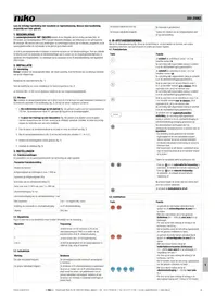
Tip: Do not install the detector in the vicinity of heat sources such as stoves or electric heaters, air currents (ventilation systems) or any moving objects (fig. 2). This can activate the device unnecessarily as it reacts to motion and heat in its surroundings.
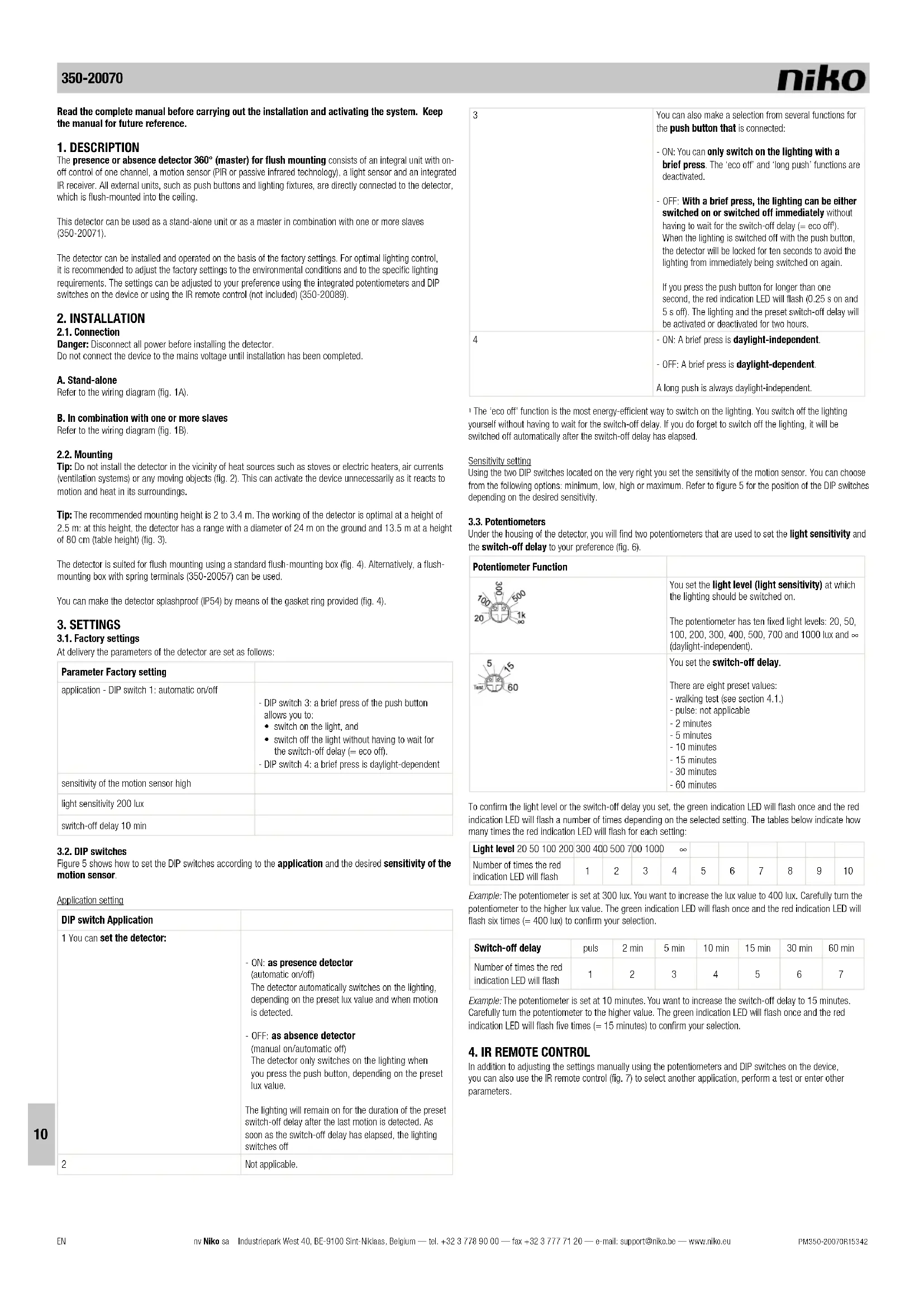
Tip: The recommended mounting height is 2 to 3.4 m. The working of the detector is optimal at a height of 2.5 m: at this height, the detector has a range with a diameter of 24 m on the ground and 13.5 m at a height of 80 cm (table height) (fig. 3).
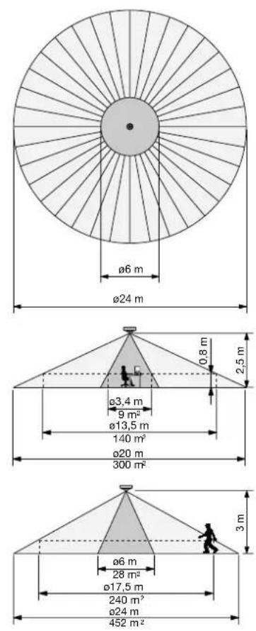
The detector is suited for flush mounting using a standard flush-mounting box (fig. 4). Alternatively, a flush-mounting box with spring terminals (350-20057) can be used.
You can make the detector splashproof (IP54) by means of the gasket ring provided (fig. 4).
3. SETTINGS
3.1. Factory settings
At delivery the parameters of the detector are set as follows:
| Parameter Factory setting | |
| application - DIP switch 1: automatic on/off | - DIP switch 3: a brief press of the push button allows you to:• switch on the light, and• switch off the light without having to wait for the switch-off delay (= eco off).- DIP switch 4: a brief press is daylight-dependent |
| sensitivity of the motion sensor high | |
| light sensitivity 200 lux | |
| switch-off delay 10 min |
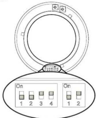
3.2. DIP switches
Figure 5 shows how to set the DIP switches according to the application and the desired sensitivity of the motion sensor.
Application setting
| DIP switch Application | |
| 1 You can set the detector: | - ON: as presence detector(automatic on/off)The detector automatically switches on the lighting,depending on the preset lux value and when motion is detected.- OFF: as absence detector(manual on/automatic off)The detector only switches on the lighting when you press the push button, depending on the preset lux value.The lighting will remain on for the duration of the preset switch-off delay after the last motion is detected. As soon as the switch-off delay has elapsed, the lighting switches off |
| 2 | Not applicable. |
| 3 | You can also make a selection from several functions for the push button that is connected:- ON: You can only switch on the lighting with a brief press. The 'eco off' and 'long push' functions are deactivated.- OFF: With a brief press, the lighting can be either switched on or switched off immediately without having to wait for the switch-off delay (= eco off').When the lighting is switched off with the push button, the detector will be locked for ten seconds to avoid the lighting from immediately being switched on again.If you press the push button for longer than one second, the red indication LED will flash (0.25 s on and 5 s off). The lighting and the preset switch-off delay will be activated or deactivated for two hours. |
| 4 | - ON: A brief press is daylight-independent.- OFF: A brief press is daylight-dependent.A long push is always daylight independent. |
The 'eco off' function is the most energy-efficient way to switch on the lighting. You switch off the lighting yourself without having to wait for the switch-off delay. If you do forget to switch off the lighting, it will be switched off automatically after the switch-off delay has elapsed.
Sensitivity setting
Using the two DIP switches located on the very right you set the sensitivity of the motion sensor. You can choose from the following options: minimum, low, high or maximum. Refer to figure 5 for the position of the DIP switches depending on the desired sensitivity.
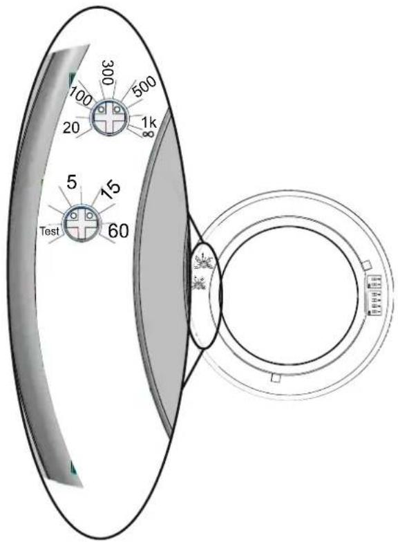
3.3. Potentiometers
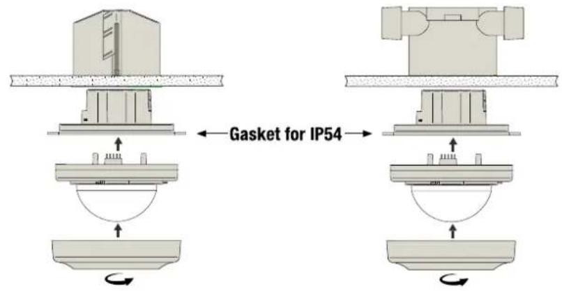
Under the housing of the detector, you will find two potentiometers that are used to set the light sensitivity and the switch-off delay to your preference (fig. 6).
| Potentiometer Function | ||
 | You set the light level (light sensitivity) at which the lighting should be switched on.The potentiometer has ten fixed light levels: 20, 50, 100, 200, 300, 400, 500, 700 and 1000 lux and (daylight-independent). | |
 | You set the switch-off delay.There are eight preset values:- walking test (see section 4.1.)- pulse: not applicable- 2 minutes- 5 minutes- 10 minutes- 15 minutes- 30 minutes- 60 minutes | |
To confirm the light level or the switch-off delay you set, the green indication LED will flash once and the red indication LED will flash a number of times depending on the selected setting. The tables below indicate how many times the red indication LED will flash for each setting:
| Light level 20 50 100 200 300 400 500 700 1000 ∞ | ||||||||||
| Number of times the red indication LED will flash | 1 | 2 | 3 | 4 | 5 | 6 | 7 | 8 | 9 | 10 |
Example: The potentiometer is set at 300 lux. You want to increase the lux value to 400 lux. Carefully turn the potentiometer to the higher lux value. The green indication LED will flash once and the red indication LED will flash six times (= 400 lux) to confirm your selection.
| Switch-off delay | puls | 2 min | 5 min | 10 min | 15 min | 30 min | 60 min |
| Number of times the red indication LED will flash | 1 | 2 | 3 | 4 | 5 | 6 | 7 |
Example: The potentiometer is set at 10 minutes. You want to increase the switch-off delay to 15 minutes. Carefully turn the potentiometer to the higher value. The green indication LED will flash once and the red indication LED will flash five times (= 15 minutes) to confirm your selection.
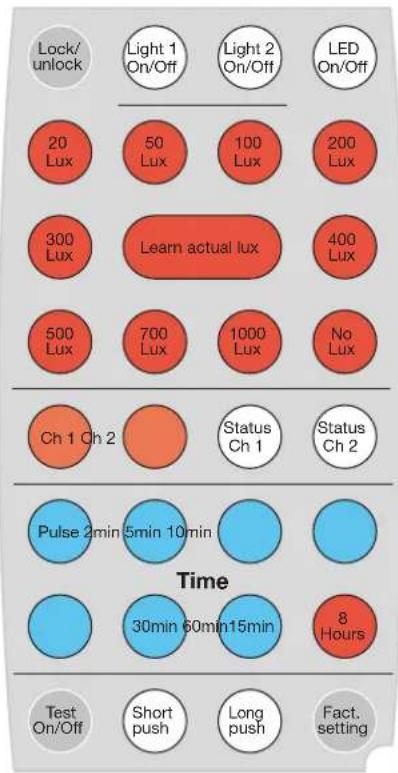
4. IR REMOTE CONTROL
In addition to adjusting the settings manually using the potentiometers and DIP switches on the device, you can also use the IR remote control (fig. 7) to select another application, perform a test or enter other parameters.
4.1. Function buttons
| Button Function | |
| [xGO2] | Youswitch the light permanently on or off, irrespective of the detected movement and the light level.Briefly pressor follow the steps below to activate this function:1. Pressto switch the lighting on or off.If the function is activated, the red indication LED will flash (1 s on, 10 s off).2. Pressto switch the lighting on or off again.3. Pressagain.The detector will return to the selected settings. The red indication LED will flash once to confirm. |
| You switch theindication LED on or off.The indication LED will flash whenorisactivated. | |
| If you press this button, the device will show the current settings for channel 1 via the indication LEDs.First, the green indication LED flashes once, after which the red indication LED indicates the status. The first time the red indication LED flashes, it indicates the lux level you set; the second time, this LED refers to the switch-off delay (see also the tables in section 3.3.).Example: Channel 1 is set at 300 lux and 10 minutes.Press: the green indication LED flashes once and the red indication LED flashes five times (= 300 lux), after which the green indication LED flashes once again and the red indication LED flashes four times (= 10 min). | |
| [SHK2] | The detection area is tested by activating the integrated motion sensor for thewalking test:- The blue indication LED lights up when you activate the test mode.- The lighting is switched on for five seconds and the red indication LED lights up each time the sensor detects activity.- If no activity is detected and the sensor is still in test mode, the blue indication LED lights up.- If you forget to close the test mode, the detector will return to the selected settings after five minutes..The light sensor does not work during the walking test.You can also activate the walking test via the potentiometer for the switch-off delay. |
4.2. 'Set' buttons
To change the settings of the detector:
- Press three times within five seconds to unlock the device.
The green indication LED flashes twice to confirm. The device is now in 'set' mode.
-
Change the light level or the switch-off delay using the buttons below.
-
Press lock once to lock the device again.
The green indication LED flashes twice to confirm. The modified setting is activated and the device will return to the selected settings.
Note: If you do not lock the device, it will be locked automatically after two minutes. All changes will then be saved automatically.
| Button Function | |
| Press this button to set the lux value and/or the switch-off delay for channel 1.The red indication LED indicates that you can adjust the setting. | |
| - With these red buttons, you set the desired light level (lux value).- There are ten fixed lux values: 20, 50, 100, 200, 300, 400, 500, 700 and 1000 lux and No lux(daylight-independent). |
| - With this button, you set thecurrent light level in the room as the desired level at which the lighting should be switched on.- If you press this button, the red indication LED will flash once to indicate that the current light level is being saved. If this light level is not between 20 and 1000 lux, the minimum level (20 lux) or maximum level (1000 lux) will be saved.Use this setting if the desired minimum light level in the room has been achieved. This is the point at which the lighting should be switched on as the daylight level is no longer sufficient. | |
| - With these blue buttons, you set the desiredswitch-off delay.- There are six fixed values: 2, 5, 10, 15, 30 and 60 minutes. | |
| Not applicable. | |
| Press this button:- The lighting will beswitched on permanently for eight hours.- The blue indication LED will flash (0.25 s on and 2 s off).Press this button again to deactivate the function. The blue indication LED will no longer flash. You cannot switch off this function via a push button. | |
| The devicereturns to the factory settings. |
5. OPERATION AND USE
5.1. Activation
The detector should not be powered until all cables are connected. After powering the device, the detector will be ready for use after approximately 120 seconds (warm-up time).
The red indication LED flashes during warm-up time. After the device has warmed up, the green indication LED will flash briefly twice.
5.2. General operation
The integrated light sensor continuously measures the daylight level in the detection area and compares this level to the preset lux value. Thanks to the light sensor, the light switches on automatically only if the detector detects motion within the detection range and if there is insufficient daylight:
- The lighting remains switched on as long as motion is detected and the amount of daylight available in the room is insufficient.
- After the last motion is detected, the lighting remains switched on for the duration of the preset switch-off delay (1 to 60 minutes). As soon as the switch-off delay has elapsed, the lighting switches off.
- The lighting also switches off automatically as soon as the daylight level is sufficiently high, even when motion is still detected in the room at that time.
5.3. Detection range
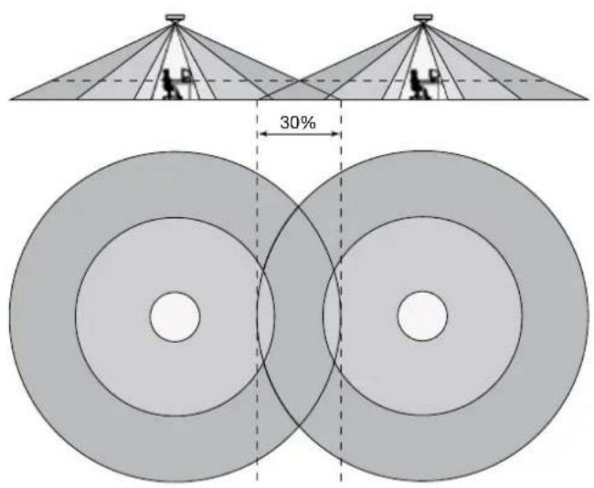
The detection area can be increased by adding an extra detector (slave) (350-20071). A maximum of ten slaves can be connected to one master (350-20070). The lighting is operated in accordance with the settings on the master. Both the master and the slave have the same detection range (a circle with a diameter of 24 m). When covering a complete area using several detectors, it is recommended to take into account an overlap of approximately 30% (fig. 8).
If you would like to exclude motion detection in a portion of the detection area or if the detection area is too large, you cover the sensor lens using the cover cap supplied. This allows you to reduce the maximum range to 24 m. The 360° detection angle can be reduced in steps of 30°.
5.4. Examples of applications
Example 1: classroom
| DIP switch 1 | DIP switch 3 | DIP switch 4 | |
| ON x x | |||
| OFF | x |
How the presence detector works:
- The lighting is automatically switched on when the detector detects motion in the detection area and the light level is less than the preset lux value.
- The lighting is automatically switched off again after a preset time (switch-off delay), provided that no more motion is detected by the detector in the detection area or the light level has been higher than the preset lux value for five minutes.
- The lighting can be switched on manually at any time by briefly pressing the push button. You can also switch off the lighting manually (= eco off).
- In addition, you can also press and hold the push button, which is ideal for situations in which the lighting should remain switched on (e.g. exam) or off (e.g. movie) for a longer period of time:
- By pressing and holding the push button while the lighting is switched on, the lighting will be switched off. The detector will be locked for as long as activity is detected and the preset switch-off delay + 2 hours has not yet elapsed. After that, the detector will return to the selected settings and the lighting will be switched on.
- By pressing and holding the push button while the lighting is switched off, the lighting will be switched on (irrespective of the daylight level). The lighting remains switched on for as long as activity is detected
and the preset switch-off delay + 2 hours has not yet elapsed. After that, the lighting will be switched off, the detector will return to the selected settings and the lighting will be switched on.
The red indication LED on the detector flashes (0.25 s on and 5 s off) to indicate that you have pressed and held the push button. The 'long push' function can be interrupted at any time by briefly pressing the push button, after which the lighting will be switched on and the detector will return to the selected settings.
Example 2: office
| DIP switch 1 | DIP switch 3 | DIP switch 4 | |
| ON x x | |||
| OFF x |
How the absence detector works:
- The lighting must be switched on by briefly pressing the push button (daylight-independent).
- The 'eco off' and 'long push' functions are deactivated.
- The lighting is automatically switched off again after a preset time (switch-off delay), provided that no more motion is detected by the detector in the detection area or the light level has been higher than the preset lux value for five minutes.
Example 3: staircase
| DIP switch 1 | DIP switch 3 | DIP switch 4 | |
| ON x x x | |||
| OFF |
How the presence detector works:
- The lighting is automatically switched on when the detector detects motion in the detection area and the light level is less than the preset lux value.
- The lighting is automatically switched off again after a preset time (switch-off delay), provided that no more motion is detected by the detector in the detection area or the light level has been higher than the preset lux value for five minutes.
- The lighting can be switched on manually at any time via the push button, irrespective of the daylight level.
6. MAINTENANCE
Dirt may prevent the detector from functioning properly. Therefore, always keep the lens clean and dry. Use a damp cloth and water with some detergent to clean the lens. Never exert pressure to wipe the lens clean. If the lens or other parts of the detector are defective, please contact an authorised installer.
- TECHNICAL DATA
| dimensions | 46.4 x 100 mm (HxB)73.4 x 100 mm (HxW) (including non-visible part) |
| power supply voltage 230 Vac ± 10%, 50 Hz | |
| power consumption 0.2 W | |
| relay contact NO (max. 10 A), potential-free, | light- and motion-sensitive |
| maximum load | incandescent lamps (2300 W) |
| 230 V halogen lamps (2300 W) | |
| all low-voltage halogen lamps (500 VA) | |
| fluorescent lamps (non-compensated) (1200 VA) | |
| economy lamps (CFLI) (1200 VA) | |
| maximum switching capacity 140 μF | |
| maximum inrush current 165 A/20 ms | |
| light sensitivity 20 – 1000 lux | |
| hysteresis on light sensitivity + 10% | |
| switch-off delay | 2 – 60 min |
| mounting height (fig. 3) | 2 – 3.4 m |
| detection angle (fig. 3) | 360° |
| detection range (fig. 3) | circular, 3 – 24 m |
| wire input | 3 x 2.5 mm2 |
| protection degree | IP54 |
| protection class | class I devices |
| ambient temperature -5 – +50°C | |
| quality mark | CE marked in compliance with EN 60669-2-1 |
| accessories | IR remote control (350-20089) |
| presence or absence detector 360° (slave) (350-20071) | |
| flush mounting box with spring terminals (350-20057) |
8. WARNINGS REGARDING INSTALLATION
- The installation should be carried out by a registered installer and in compliance with the statutory regulations.
- This user manual should be presented to the user. It should be included in the electrical installation file, and it should be passed on to any new owners. Additional copies are available on the Niko website or via the Niko support service.
- During installation, the following should be taken into account (non-exhaustive list):
- the statutory laws, standards and regulations.
- the technology currently available at the time of installation.
- this user manual, which only states general regulations and should therefore be read within the scope of each specific installation.
- the rules of proper workmanship.

This product complies with all of the relevant European guidelines and regulations. If applicable, you can find the EC declaration of conformity regarding this product at www.niko.eu.
9. NIKO SUPPORT
In case of doubt or for the specific exchange procedure in case of a possible defect, contact the Niko support service in Belgium at +32 3 778 90 80 or your wholesaler/installer. Contact details and more information can be found at www.niko.eu under the "Help and advice" section.
10.GUARANTEE PROVISIONS
- The period of guarantee is four years from the date of delivery. The delivery date is the invoice date of purchase of the product by the consumer. If there is no invoice, the date of production applies.
- The consumer is obliged to inform Niko in writing about the non-conformity, within two months after stating the defect.
- In case of a non-conformity, the consumer only has the right to a product repair or replacement free of charge, which shall be decided by Niko.
- Niko shall not be held liable for a defect or damage resulting from incorrect installation, improper or careless use, incorrect operation, transformation of the product, maintenance that does not adhere to the maintenance instructions or an external cause, such as damage due to moisture or overvoltage.
- The compulsory regulations of the national legislation concerning the sale of consumer goods and the protection of the consumer in the countries where Niko sells, directly or via sister companies, subsidiaries, chain stores, distributors, agents or permanent sales representatives, take priority over the above-mentioned rules and regulations.

Do not dump this product with the unsorted waste. Bring it to a recognised waste collection point. Together with producers and importers, you have an important role to play in the advancement of sorting, recycling and reusing discarded electrical and electronic appliances. In order to finance the waste collection and processing, the government levies a recycling contribution in some cases (included in the purchase price of this product).
text_image
Diagram showing four distinct visual icons: sun, battery, robot, and office with directional arrows.Fig./Abb./Obr. 3
text_image
ø6 m ø24 m ø3,4 m 9 m² ø13,5 m 140 m² ø20 m 300 m² ø6 m 28 m² ø17,5 m 240 m² ø24 m 452 m² 0,8 m 2,5 m 3 mFig./Abb./Obr. 4
text_image
Gasket for IP54Fig./Abb./Obr. 5
text_image
On 1 2 3 4 On 1 2DIP switch:
Application
Factory setting:
1 = On
2 = On
3 = Off
4 = Off
DIP switch:
Sensitivity
On = 1 / Off = 0
DIP 12
0.0: Min
01: Low
10: High (Factory setting)
11: Max
Fig./Abb./Obr. 7
text_image
Lock/ unlock 20 Lux 300 Lux 500 Lux Ch 1 Ch 2 Pulse 2min 5min 10min Test On/Off Light 1 On/Off 50 Lux 700 Lux 700 Lux Light 2 On/Off 100 Lux 1000 Lux Status Ch 1 Status Ch 2 60min 60min 15min 8 Hours Long push Fact. settingFig./Abb./Obr. 6
text_image
100 20 300 500 1k 5 15 60 TestFig./Abb./Obr. 8