35020054 - Smart Home Niko - Free user manual and instructions
Find the device manual for free 35020054 Niko in PDF.
| Product type | Passive infrared presence detector |
| Brand | Niko |
| Model | 350-20054 |
| Category | Smart home |
| Dimensions | 59 × 127 mm (HxW) |
| Weight | Approx. 200 g (estimated) |
| Supply voltage | 230 Vac ± 10% |
| Power consumption | < 1 W (1-channel model) |
| Detection angle | 360° |
| Detection range | Up to 20 m (diameter) |
| Recommended mounting height | 2.5 to 3 m |
| Light sensitivity | 10 - 1000 lux (adjustable) |
| Off delay | 1 to 30 min (adjustable) |
| Maximum load (lighting) | Up to 2300 W (incandescent/halogen) |
| Protection rating | IP20 |
| Protection class | Class II |
| Ambient temperature | -5 to 50°C |
| Main functions | Presence detection, automatic on/off, manual mode via push button, brightness and delay settings, test mode |
| Maintenance and cleaning | Clean the lens with a damp cloth and a little detergent. Do not apply pressure. |
| Safety | Electrical installation by a certified installer. Disconnect power before connection. |
Frequently Asked Questions - 35020054 Niko
User questions about 35020054 Niko
0 question about this device. Answer the ones you know or ask your own.
Ask a new question about this device
Download the instructions for your Smart Home in PDF format for free! Find your manual 35020054 - Niko and take your electronic device back in hand. On this page are published all the documents necessary for the use of your device. 35020054 by Niko.
USER MANUAL 35020054 Niko
7. WAARSCHUWINGEN VOOR INSTALLATIE
Read the complete user manual before carrying out the installation and activating the system.
1.DESCRIPTION
The presence detector for ceiling mounting uses Passive Infrared Technology (PIR) and is suitable for indoor use. Lighting control through motion detection is useful for small and large offices, rest rooms, changing rooms and larger storage areas.
The 1-channel presence detector (350-20054) controls only interior lighting. The 2-channel presence detector (350-20055) has an additional potential-free relay contact to control interior lighting as well as ventilation.
2. INSTALLATION
2.1. Positioning
The presence detector reacts to motion and heat in its environment.
Installation tips:
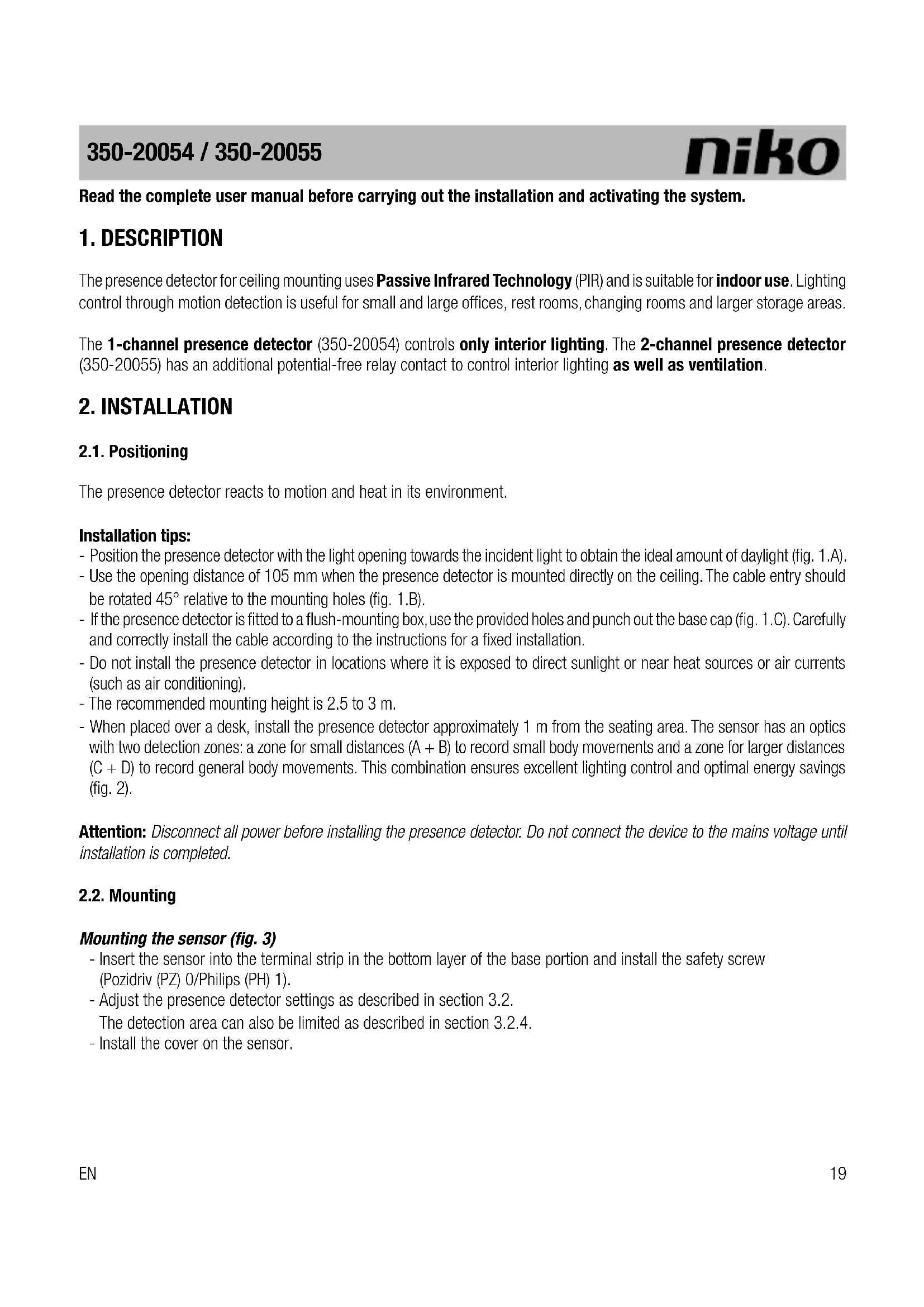
- Position the presence detector with the light opening towards the incident light to obtain the ideal amount of daylight (fig. 1.A).
- Use the opening distance of 105mm when the presence detector is mounted directly on the ceiling. The cable entry should be rotated 45^ relative to the mounting holes (fig. 1.B).
- If the presence detector is fitted to a flush-mounting box, use the provided holes and punch out the base cap (fig. 1.C). Carefully and correctly install the cable according to the instructions for a fixed installation.
- Do not install the presence detector in locations where it is exposed to direct sunlight or near heat sources or air currents (such as air conditioning).
- The recommended mounting height is 2.5 to 3m
- When placed over a desk, install the presence detector approximately 1m from the seating area. The sensor has an optics with two detection zones: a zone for small distances (A + B) to record small body movements and a zone for larger distances (C + D) to record general body movements. This combination ensures excellent lighting control and optimal energy savings (fig. 2).
Attention: Disconnect all power before installing the presence detector. Do not connect the device to the mains voltage until installation is completed.
2.2. Mounting
Mounting the sensor (fig. 3)
- Insert the sensor into the terminal strip in the bottom layer of the base portion and install the safety screw (Pozidriv (PZ) 0/Philips (PH) 1).
- Adjust the presence detector settings as described in section 3.2.
The detection area can also be limited as described in section 3.2.4.
- Install the cover on the sensor.
Connecting the presence detector (fig. 4 and 5)
- Switch off the mains supply.
Power is supplied from the mains via terminals L, and N.
- Connect the lighting via terminals N and @fig. 5.1).
Connect a push button between terminals L and if manual operation of the presence detector is also desired (fig. 5.2).
- Connect the ground wire to terminal
3. OPERATION AND SETTINGS
3.1. Operation
3.1.1. General
The presence detector is ready to use three to five minutes after connecting to the mains voltage (warm-up time). The connected lighting will be switched off as soon as the device is ready to use.
3.1.2. Automatic ON
The integrated light sensor continuously measures the light level in the detection zone and compares this level with the preset value specified using the LUX key. The light sensor automatically switches the lighting on only when the detector detects motion within the detection range and when the daylight level drops below the preset lux value. The lighting remains on as long as motion is detected.
The ventilation output of the 2-channel detector is activated, regardless of the daylight level.
3.1.3. Automatic OFF
The lighting automatically switches off when the preset daylight level is reached.
The TIME key is used to set the switch-off delay as desired. The lighting will remain on for the specified delay time after the last motion is detected. Once the switch-off delay has expired, the lighting will switch off.
Attention: The switch-off delay on channel 1 must be set to at least 5 minutes to ensure that the 25% increase on channel 2 will be activated. If the switch-off delay on channel 1 is less than 5 minutes, channels 1 and 2 will be switched at the same time.
3.1.4. Manual ON/OFF
The lighting can also be manually switched on and off by pressing the 230 Vac NO push button, regardless of the measured daylight level.
- A long press ( >2 s) on the push button with the lighting switched off, will switch the lighting on. The lighting will remain on. A short press ( <2 s) on the push button will switch the lighting off. The automatic mode is now activated.
- A short press (< 2 s) on the push button with the lighting automatically switched on, will switch the lighting off. The automatic mode is reactivated after ten seconds to allow time to leave the detection area.
- A long press (>2s) on the push button with the lighting automatically switched on, will switch the lighting off permanently. The presence detector is now disabled. Press the push button briefly (< 2s) to switch the lighting on again. The automatic mode is now activated.
3.2. Settings
3.2.1. General
At delivery, the light sensor parameters are set as follows (factory settings):
| sensor mode automatic | |
| sensitivity high | |
| LED motion indicator off |
Use DIP switches 1 and 2 to set the presence detector to the desired test mode and activate the LED motion indicator. To set the sensitivity, use DIP switches 3 and 4. Figure 7 shows how to set the DIP switches for the desired sensitivity of the light sensor (minimum, low, high, maximum).
3.2.2. Test modes
The presence detector has two test modes: a test mode for the lux value and a test mode for the motion detector operation.
a) Test mode for the lux value: measuring the daylight level
Set DIP switches 1 and 2 to ON. The lighting is now switched off.
Slowly turn the LUX key clockwise (towards maximum) until the LED indicator illuminates. The lux setting is then equal to the daylight level the light sensor is measuring. If there is sufficient daylight in the room, turn the LUX key counterclockwise until the LED indicator switches off. Leave the LUX key in this position.
If the LUX key is turned counterclockwise, the lighting switches off when there is less daylight.
If the LUX key is turned clockwise, the lighting switches off when there is more daylight.
Finally, reset DIP switches 1 and 2 to OFF.
b) Test mode for the motion detector operation
Set DIP switch 1 to OFF and DIP switch 2 to ON. The lighting is switched on for five seconds. The LED motion indicator indicates that the motion detector is activated.
Attention: The walking is not affected by daylight.
Finally, reset DIP switch 2 to OFF.
3.2.3. LED motion indicator
Set DIP switch 1 to ON and DIP switch 2 to OFF to activate to LED motion indicator. The LED indicator remains illuminated as long as motion is detected.
3.2.4. Detection range
If the presence detector is mounted at a height of 2.5m , it detects movement within a diameter of 20m in a 360^ zone. This presence detector has a lens area with a diameter of 5m and more than 618 fields, which guarantees optimal registration of even the smallest body movements.
If a section of the detection area is to be excluded from detecting any motion, cover the sensor lens using the cover cap supplied. This allows the maximum range to be reduced from 20m to 12m, 5m or 3m . The detection angle of 360^ can be decreased in steps of 45^ (fig. 7).
EN
4. MAINTENANCE
Dirt may prevent the presence detector from functioning properly. Therefore, always keep the lens clean and dry. Use a damp cloth and water with some detergent to clean the lens. Never exert pressure to wipe the lens clean. The presence detector should be replaced if the lens or other parts of the presence detector are defective.
5. TROUBLESHOOTING
| Problem Cause Solution | ||
| The lighting/ventilator does not switch on. | Internal error. Switch the mains power off for at least five seconds and then switch it back on. | |
| Defective lamp/ventilator. Test whether the lamp/ventilator itself is still working. | ||
| Incorrect wiring. Check the wiring against the wiring diagram. | ||
| There is no power supply voltage on the sensor. | Check whether there is power supply voltage on the sensor. | |
| Incorrectly set lux value. Ensure the lux value is set to the desired light intensity. | ||
| The lighting/ventilator does not switch off. | Switch-off delay set too long. Ensure the switch-off delay is not set too long (using the TIME key). | |
| The presence detector is still detecting movement. | Leave the detection zone to prevent to presence detector from re-activating. | |
| Power supply voltage fluctuations. Ensure the power supply voltage is constant. | ||
| The presence detector is subject to temperature fluctuations. | Ensure the presence detector is not pointed towards an object that may cause temperature fluctuations, such as air conditioning or a heating installation. | |
| After setting the lux value, the presence detector remains permanently on, regardless of the setting. | Internal error. Switch the mains power off for at least five seconds and then switch it back on. | |
6. TECHNICAL DATA
Dimensions: 59 × 127 mm (HxW)
Power supply voltage: 230 Vac ± 10%
Power consumption: < 1 W (350-20054)
< 1.5 W (350-20055)
Relay contact channel 1 and 2: NO (max. 10 A), light- and motion-sensitive
Maximum load: incandescent lamps (2300 W)
230 V halogen lamps (2300 W)
all low-voltage halogen lamps (500 VA)
fluorescent lamps (non-compensated) (1200 VA)
economy lamps (CFLi) (1200 VA)
ventilation motor (690 VA)
Maximum switching capacity: 140 uF
Maximum intrush current: 80 A/20 ms
Detection angle: 360^
Mounting height: 2.5 - 3m
Detection range: circle, up to max. 20m
Light sensitivity: 10 - 1000 lux
Hysteresis on light sensitivity: + 10%
Switch-off delay channel 1: 1 - 30 min
Switch-off delay channel 2: channel 1 value + 25%
Protection degree: IP20
Protection class: class II devices
Ambient temperature: -5 - 50^
Cable inlet:
Quality mark:
2 × 12 ~mm
CE marked in compliance with EN 60669-2-1
7. WARNINGS REGARDING INSTALLATION
-
The installation should be carried out by a registered installer and in compliance with the statutory regulations.
-
This user manual should be presented to the user. It should be included in the electrical installation file, and it should be passed on to any new owners. Additional copies are available on the Niko website or via the Niko support service.
-
During installation, the following should be taken into account (non-exhaustive list):
-
the statutory laws, standards and regulations.
- the technology currently available at the time of installation.
- this user manual, which only states general regulations and should therefore be read within the scope of each specific installation.
- the rules of proper workmanship.
8. NIKO SUPPORT
In case of doubt or for the specific exchange procedure in case of a possible defect, contact the Niko support service in Belgium at +32 3 778 90 80 or your wholesaler/installer. Contact details and more information can be found at www.niko.eu under the "Help and advice" section.
9. GUARANTEE PROVISIONS
- The period of guarantee is four years from the date of delivery. The delivery date is the invoice date of purchase of the product by the consumer. If there is no invoice, the date of production applies.
- The consumer is obliged to inform Niko in writing about the non-conformity, within two months after stating the defect.
In case of a non-conformity, the consumer only has the right to a product repair or replacement free of charge, which shall be decided by Niko. - Niko shall not be held liable for a defect or damage resulting from incorrect installation, improper or careless use, incorrect operation, transformation of the product, maintenance that does not adhere to the maintenance instructions or an external cause, such as damage due to moisture or overvoltage.
- The compulsory regulations of the national legislation concerning the sale of consumer goods and the protection of the consumer in the countries where Niko sells, directly or via sister companies, subsidiaries, chain stores, distributors, agents or permanent sales representatives, take priority over the above-mentioned rules and regulations.
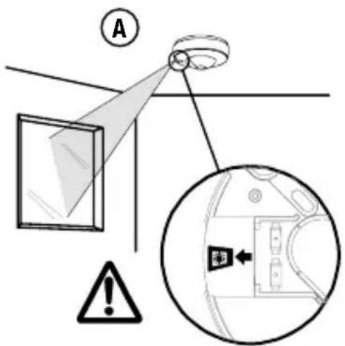
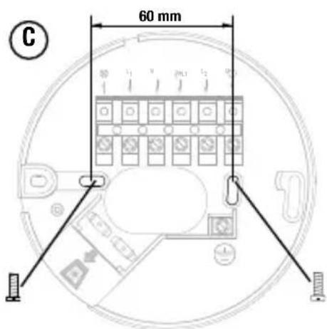
Fig./Abb. 1
Bovenaanzicht
Vue de dessus
Draufsicht
Top view
Zijaanzicht
Vue de côte
Seitenansicht
Side view
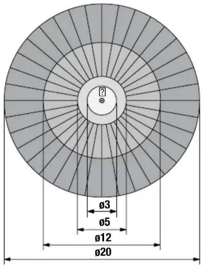
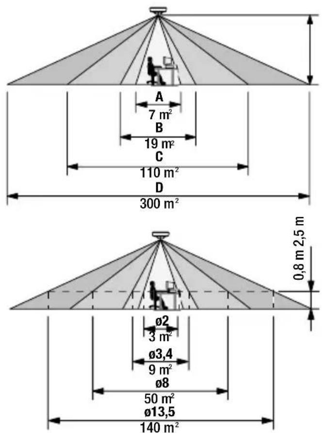
Fig./Abb. 2
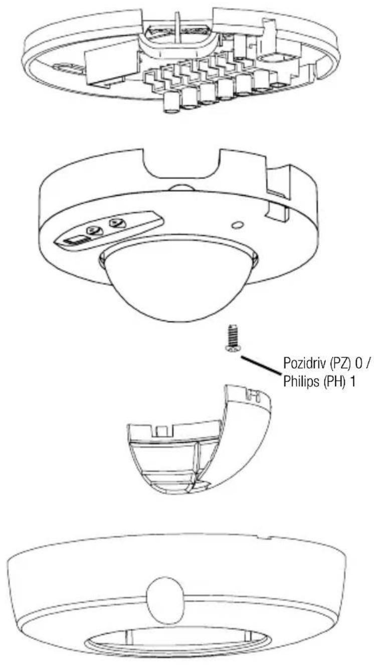
Fig./Abb. 3
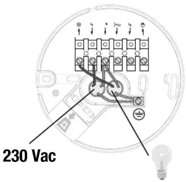
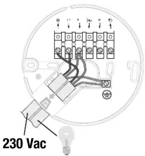
Fig./Abb. 4
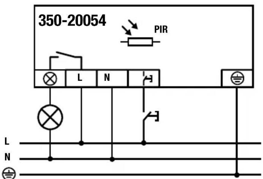
Fig./Abb. 5.1