35020062 - Smart Home Niko - Free user manual and instructions
Find the device manual for free 35020062 Niko in PDF.
| Product type | 360° presence detector with DALI/DSI control |
| Brand | Niko |
| Model | 35020062 |
| Dimensions (H x W) | 59 x 127 mm |
| Power supply | 230 Vac ± 10%, 50 Hz |
| Standby consumption | 0.3 W (without ballasts) |
| Bus output | DALI/DSI 1 and 2, max. 30 mA or 20 ballasts |
| Light sensitivity | 50 - 1500 lux |
| Disconnection delay | 1 to 60 minutes |
| Orientation lighting level | 5 to 100% |
| Orientation lighting duration | 0 to 60 minutes or infinite |
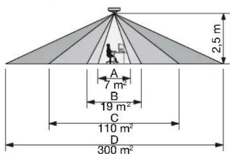
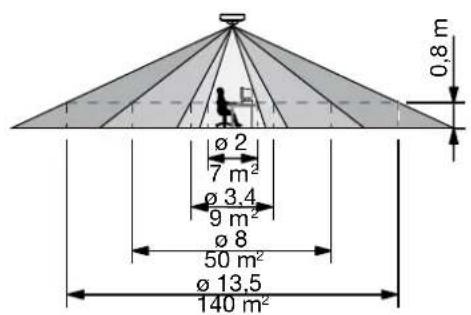
| Detection range | Circular, 3 to 20 m (depending on mounting height) |
| Recommended mounting height | 2.5 to 4 m |
| Protection rating | IP20 |
| Protection class | Class I |
| Ambient temperature | -5 to +50°C |
| Approvals | CE, EN 60669-2-1 |
| Main functions | PIR presence detection, brightness sensor, DALI/DSI lighting control in two zones, optional IR remote control |
| Maintenance and cleaning | Clean the lens with a damp cloth and mild detergent, without pressure |
| Safety | Installation by a certified electrician, compliance with applicable standards |
| Spare parts and repairability | IR remote control (350-20064) available as accessory |
| Warranty | 4 years from the date of delivery |
Frequently Asked Questions - 35020062 Niko
User questions about 35020062 Niko
0 question about this device. Answer the ones you know or ask your own.
Ask a new question about this device
Download the instructions for your Smart Home in PDF format for free! Find your manual 35020062 - Niko and take your electronic device back in hand. On this page are published all the documents necessary for the use of your device. 35020062 by Niko.
USER MANUAL 35020062 Niko
Read the complete manual before carrying out the installation and activating the system. Keep the manual for future reference.
1.DESCRIPTION
The 360^ presence detector (DALI/DSI) consists of an integral unit with control of two DALI or DSI buses, a motion sensor (PIR or passive infrared technology), a light sensor and an integrated IR receiver. All external units, such as push buttons and lighting fixtures, are directly connected to the presence detector, which is mounted directly on the ceiling.
The presence detector can be installed and operated on the basis of the factory settings. For optimal lighting control, it is recommended to adjust the factory settings to the environmental conditions and to the specific lighting requirements. The settings can be adjusted using the IR remote control (not included) (350-20064).
2. INSTALLATION
2.1. Connection
Danger: Disconnect all power before installing the presence detector. Do not connect the device to the mains voltage until installation has been completed.
Refer to the wiring diagram (fig. 1).
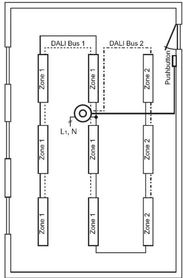
For dividing the area into zones, refer to the basic circuit diagram (fig. 2).
The DALI or DSI bus and push button must be installed as a high-voltage installation.
2.2. Mounting
Tip: Do not install the presence detector in direct sunlight or in the vicinity of heat sources (radiators) or air currents (ventilation or air conditioning) (fig. 3). This can activate the sensor unnecessarily.
- a For direct mounting on the ceiling (fig. 4A), use the holes with a centre distance of 105mm . The cable inlet must be rotated 45^ with respect to the mounting holes.
b. For mounting in a flush-mounting box (fig. 4B), use the holes provided with a centre distance of 60mm with which you push open the protection cap. Carefully install the cable following the instructions for a permanent installation. - Push the sensor onto the terminal strip on the base and tighten the screw (fig. 5).
- Set the presence detector (fig. 6) and test the device (see sections 4.1. and 4.2.).
- Reduce the detection area, if necessary (fig. 7).
- Install the protection cap (fig. 5).
3. SETTINGS
3.1. Factory settings
At delivery the parameters of the presence detector are set as follows:
| Parameter Factory setting | |
| application manual | |
| light sensitivity at table height in zone 1 300 lux | |
| hysteresis on light sensitivity 20% | |
| light level of the orientation lighting 5% | |
| factor for zone 2 100% of zone 1 (= 300 lux) | |
| switch-off delay 10 min | |
| switch-off delay of the orientation lighting 1 min | |
| DALI fade factor | 0 (0 - 15 according to DALI standard) |
| lux value and switch-off delay setting | via IR remote control |
| output | DALI bus |
3.2. DIP switches
Figure 6 shows how to set the DIP switches according to their application.
| DIP switch | Application |
| 1 | You select this to set the lux value (LUX) and the switch-off delay (TIME) via the potentiometers or the IR remote control. |
| 2 | You choose between DALI and DSI daylight control. |
| 3 and 4 | You set the sensitivity of the motion sensor: minimum, low, high or maximum. |
3.3. Indication LEDs
| Mode of operation | Meaning |
| The red indication LED is flashing. | The presence detector detects presence in test mode. |
| The green indication LED is flashing. | The push button or the IR remote control is activated. When you press a button on the IR remote control while the sensor is not locked, and the green indication LED is not flashing, it means the sensor has already reached its minimum or maximum settings. |
| The blue indication LED is illuminated. | The test mode has been selected. |
The blue indication LED is flashing. While you are setting the light sensitivity, this indicates overlighting.
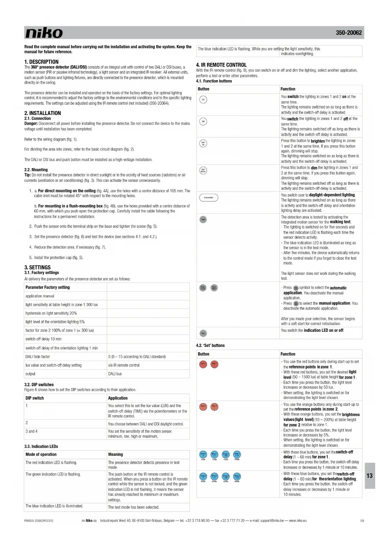
4. IR REMOTE CONTROL
With the IR remote control (fig. 8), you can switch on or off and dim the lighting, select another application, perform a test or enter other parameters.
4.1. Function buttons
| Button | Function |
| On | You switch the lighting in zones 1 and 2 on at the same time. The lighting remains switched on as long as there is activity and the switch-off delay is activated. |
| Off | You switch the lighting in zones 1 and 2 off at the same time. The lighting remains switched off as long as there is activity and the switch-off delay is activated. |
| Dim | Press this button to brighten the lighting in zones 1 and 2 at the same time. If you press this button again, dimming will stop. The lighting remains switched on as long as there is activity and the switch-off delay is activated. |
| Dim Color | Press this button to dim the lighting in zones 1 and 2 at the same time. If you press this button again, dimming will stop. The lighting remains switched off as long as there is activity and the switch-off delay is activated. |
| Automatic | You switch over to daylight-dependent lighting. The lighting remains switched on as long as there is activity and the switch-off delay and orientation lighting delay are activated. |
| Seed | The detection area is tested by activating the integrated motion sensor for the walking test. - The lighting is switched on for five seconds and the red indication LED is flashing each time the sensor detects activity. - The blue indication LED is illuminated as long as the sensor is in the test mode. - After five minutes, the device automatically returns to the control mode if you forget to close the test mode. The light sensor does not work during the walking test. |
| Auto Auto Auto | - Press symbol to select the automatic application. You deactivate the manual application. - Press to select the manual application. You deactivate the automatic application. After you made your selection, the sensor begins with a soft start for correct initialisation. |
| Auto | You switch the indication LED on or off. |
4.2. 'Set' buttons
| Button | Function |
| Set 1 Set 2 Set 3 | - You use the red buttons only during start-up to set the reference points in zone 1. - With these red buttons, you set the desired light level (50 - 1500 lux) at table height for zone 1. - Each time you press the button, the light level increases or decreases by 50 lux. - When setting, the lighting is switched on for demonstrating the light level chosen. |
| Set 2 Set 3 | - You use the orange buttons only during start-up to set the reference points in zone 2. - With these orange buttons, you set the brightness values (light level) (10 - 200%) at table height for zone 2 relative to zone 1. - Each time you press the button, the light level increases or decreases by 5%. - When setting, the lighting is switched on for demonstrating the light level chosen. |
| Time 1 Time 2 Time 3 | - With these blue buttons, you set the switch-off delay (1 - 60 min) for zone 1. - Each time you press the button, the switch-off delay increases or decreases by 1 minute or 10 minutes. |
| Time 3 Time 4 | - With these blue buttons, you set the switch-off delay (1 - 60 min) for orientation lighting. - Each time you press the button, the switch-off delay increases or decreases by 1 minute or 10 minutes. |
| Face 1200K | Face 1500K | |
| - With these buttons, you set the fade time (0 - 15) for DALI coils or lighting fixtures - Each time you press the button, the fade time increases or decreases by 1. | ||
| Tip: You must increase the fade factor if the lighting fixtures are flashing during the transition phase. | ||
| Tip: It is recommended to keep this setting at 0 to prevent that this is regarded as a delay between the moment when the door button is pressed and the moment when there is a visible difference in the lighting. | ||
| Level 1 | Level 2 | |
| - With these buttons, you set the positive hysteresis on light sensitivity (10 - 100%) for the light level. - Each time you press the button, the hysteresis increases or decreases by 10%. | ||
| Level 2 | Level 3 | |
| - With these buttons, you set the light level of the orientation lighting (5 - 100%). - Each time you press the button, the light level increases or decreases by 5%. | ||
| Pause | - The device returns to the factory settings. - The sensor begins with a soft start for correct initialisation. - The following values are sent to the DALI coils: - failure level1 = 254 - activation level2 = 0 (switched off) - fade time3 = 0 |
1 When a DALI controller is disconnected or in the event of a defect, the lighting switches over to its maximum level (254).
2 When you activate the device, this parameter ensures that the lighting does not switch on suddenly.
The time that it takes for the lighting to go from 0 to 100% . The recommended level is 0 (otherwise this takes too long).
5. ACTIVATING THE PRESENCE DETECTOR
5.1. Manual activation via the LUX potentiometer
| Step Action Result | ||
| 1. Set DIP switch 1 to ON. You can now set the lux value manually. | ||
| 2. Turn the LUX potentiometer all the way to the left (minimum setting). | The blue indication LED starts flashing. | |
| 3. Turn the LUX potentiometer all the way to the right (maximum setting). | The blue indication LED starts flashing after a few seconds. | |
| 4. Turn the LUX potentiometer all the way to the left again (minimum setting). | a. The green indication LED is flashing once. b. The sensor switches on the lighting in zones 1 and 2, after which the maximum light level is reached. c. The lighting in zone 1 is dimmed, and then switched off in zones 1 and 2. d. The lighting in zone 2 is switched on, after which the maximum light level is reached. e. The lighting in zone 2 is dimmed. After approximately two minutes, the lighting is automatically switched off and then switched on again at the minimum light level. | |
| 5. Set the lux value of your choice using the LUX potentiometer. | The sensor records this lux value after 30 seconds. | |
5.2. Activation via the IR remote control with factory settings
| Step Action Result | ||
| 1. Set DIP switch 1 to OFF (factory setting). You can now set the lux value using the IR remote control. | ||
| 2. | Press three times. | The sensor is unlocked and the green indication LED is flashing once. |
| 3. | Press | a. The sensor switches on the lighting in zones 1 and 2, after which the maximum light level is reached. b. The lighting in zone 1 is dimmed, and then switched off in zones 1 and 2. c. The lighting in zone 2 is switched on, after which the maximum light level is reached. d. The lighting in zone 2 is dimmed. After approximately two minutes, the lighting is automatically switched off. |
| 4. | Press | The sensor is locked again and returns to the control mode. The device will now use the new settings. |
5.3. Activation via the IR remote control with calibration (sweep)
To set the presence detector in line with specific lighting requirements in certain rooms, you have to use the IR remote control. You will also need a separate lux meter for this. Using the lux meter, you send the reference values to the sensor, which ensures that the effect of switching on the lighting on the light level is accurately measured and set. Follow the steps below to correctly set the sensor.
| Step Action Result | ||
| 1. Set DIP switch 1 to OFF (factory setting). You can now set the device using the IR remote control. | ||
| 2. | Press three times. | The sensor is unlocked and the green indication LED is flashing once. |
| 3. | Press | a. The sensor switches on the lighting in zones 1 and 2. After two minutes (fluorescent lamps heating up), the maximum light level is reached. The green indication LED is flashing during this process. b. If the green indication LED goes out, the calibration will start (sweep): the lighting in zone 2 is switched off and the lighting in zone 1 is gradually dimmed and then switched off. After this, the lighting in zone 2 is gradually dimmed and then switched off. c. As soon as the calibration is completed, the red indication LED lights up and the lighting in both zones is switched on. |
| 4. Place a lux meter at table height (approximately 85 cm from the ground) underneath the sensor and centrally in zone 1. | ||
| 5. | Press or | You set the first reference point in zone 1 to the lowest light level possible (e.g. 300 lux). Note: The light level must be as close as possible to the fixed values on the IR remote control. |
| 6. Press the button with the value closest to the first reference point (e.g. ). | The red indication LED goes out and the blue indication LED lights up. The lux value is set. | |
| 7. | Press or | You set the second reference point in zone 1 to the highest light level possible (e.g. 700 lux). Note: The light level must be as close as possible to the fixed values on the IR remote control. |
| 8. Press the button with the value closest to the second reference point (e.g. ). | The blue indication LED goes out, and the red and blue indication LEDs light up at the same time. The lux value is set and the lighting in zone 2 is switched off. | |
| 9. | Press or | You set the third reference point in zone 1 to the highest light level possible (e.g. 600 lux). Note: The light level must be as close as possible to the fixed values on the IR remote control. |
| 10. Press the button with the value closest to the third reference point (e.g. ). | The red and blue indication LEDs go out, and the green indication LED lights up. The lux value is set. | |
| 11. Press the button with the value closest to the lux value of your choice (e.g. for 300 lux). | You set the lux value of your choice for zone 1 at table height. The green indication LED goes out and the red indication LED lights up. The lux value is set and the lighting in zone 2 is switched on again. | |
| 12. | Press if you only use zone 1 or if the light level of your choice in zone 2 should be the same as that in zone 1. Continue with step 21. | |
Setting the light level in zone 2
Step Action Result
| 13. Place a lux meter at table height (approximately 85 cm from the ground) underneath the sensor and centrally in zone 2. | ||
| 14. | Press or | You set the first reference point in zone 2 to the lowest light level possible (e.g. 200 lux). Note: The light level must be as close as possible to the fixed values on the IR remote control. |
| 15. Press the button with the value closest to the first reference point (e.g. ). | The red indication LED goes out and the blue indication LED lights up. The lux value is set. | |
| 16. | Press or | You set the second reference point in zone 2 to the highest light level possible (e.g. 500 lux). Note: The light level must be as close as possible to the fixed values on the IR remote control. |
| 17. Press the button with the value closest to the second reference point (e.g. ). | The blue indication LED goes out, and the red and blue indication LEDs light up at the same time. The lux value is set and the lighting in zone 1 is switched off. | |
| 18. | Press or | You set the third reference point in zone 2 to the highest light level possible (e.g. 400 lux). Note: The light level must be as close as possible to the fixed values on the IR remote control. |
| 19. Press the button with the value closest to the third reference point (e.g. ). | The red and blue indication LEDs go out, and the green indication LED lights up. The lux value is set. | |
| 20. Press the button with the value closest to the lux value of your choice (e.g. for 200 lux). | You set the lux value of your choice for zone 2 at table height. The green indication LED goes out. The lux value is set. | |
| 21. Press once. | The sensor is locked again and returns to the control mode. The device will now use the new settings. | |
5.4.Setting the hallway function
You can use the presence detector in rooms with no available daylight, such as hallways. In this case, the lighting will be used as orientation lighting, with the light level varying between 100% and one of the preset levels. Use the example below to correctly enter the settings for the hallway function of the sensor.
Example (see also figure 9): The switch-off delay of your choice, i.e. the time between the last movement and the moment at which the lighting is dimmed to a lower light level (orientation lighting), must be set to 20 minutes. The light level of the orientation lighting must be set at 20% . After 21 minutes, the lighting will be switched off.
Step Action Result
| 1. Set | DIP switch 1 to OFF (factory setting). You can now set the device using the IR remote control. | |
| 2. | Press three times. | The sensor is unlocked and the green indication LED is flashing once. |
| 3. Turn the LUX potentiometer all the way to the right (maximum setting). | a. The red indication LED starts flashing. b. As soon as the potentiometer has reached the maximum light level, the blue indication LED will light up. The hallway function is selected correctly and now activated. | |
| 4. | Press once. | The red indication LED starts flashing to indicate that the signal has been received properly. When you press this button, the factory setting for the switch-off delay (10 min) is increased by 10 minutes. The switch-off delay is now set to 20 minutes. |
| 5. | Press three times. | The red indication LED starts flashing to indicate that the signal has been received properly. When you press this button three times, the factory setting for the light level of the orientation lighting (5%) is increased by 15%. The light level is now set at 20%. |
| 6. | Press twice. | The red indication LED starts flashing to indicate that the signal has been received properly. When you press this button, the factory setting for the switch-off delay of the orientation lighting (1 min) is increased by 20 minutes. The switch-off delay of the orientation lighting is now set to 21 minutes. |
| 7. | Press once. | The sensor is locked again and returns to the control mode. The device will now use the new settings. |
6. OPERATION AND USE
6.1. General operation
The integrated light sensor continuously measures the daylight level in the detection area and compares this level to the preset lux value. Thanks to the light sensor, the light switches on automatically only if the detector detects motion within the detection range and if the daylight level falls below the preset lux value:
The lighting remains switched on as long as motion is detected.
- After the last motion is detected, the lighting remains switched on for the duration of the
preset switch-off delay (1 to 60 minutes). As soon as the switch-off delay has elapsed, the lighting switches to orientation lighting. As soon as the switch-off delay of the orientation lighting has elapsed, the lighting switches off.
- As the daylight level increases, the lighting in the room is dimmed until the preset minimum level is reached.
The lighting switches off automatically as soon as the daylight level is sufficiently high
6.2. Applications
There are two applications possible on this presence detector:
- manual application: manual on/off via push button, automatic off via presence detector, or dependent on the light level.
- automatic application (can only be selected with the IR remote control): automatic on/off via presence detector, dependent on the light level.
Mode Application Mode of operation
| Ceiling lighting manual | Switching of DAI and DSI daylight control1 in two zones via a push button. If necessary, you can switch on the lighting according to the preset parameters. As long as the device detects presence, the lighting is adjusted according to the preset parameters. | |
| automatic | Automatic switching of DAI and DSI daylight control2 in two zones via a presence detector. | |
| manual and automatic | Press the push button briefly to switch the lighting off. After approximately ten seconds the presence detector is once again ready to switch the lighting on automatically. | |
| Dimming lights | manual and automatic | Press and hold the push button to dim or brighten the lighting. You can also dim/brighten the lighting using the IR remote control. When the dim function is activated, you must switch off the lighting so that it can once again be switched on and can function according to the daylight measurements (via the integrated light sensor). |
1 The two zones are connected to their own DALI or DSI bus in zones 1 and 2.
You can also carry out these applications with the IR remote control as described in section 4.1.
- TROUBLESHOOTING
| Problem | Cause | Solution |
| The calibration was not successful: the red indication LED keeps flashing. | - Insufficient daylight (or not enough daylight is registered by the sensor).- Too much daylight, which means the sensor is saturated.- There are not enough variations in the artificial light level (or the variations are not adequately registered by the sensor).- The daylight level was varying too much during calibration. | - Press and repeat the calibration.- Press once. The sensor is locked and returns to the factory settings. |
| An error occurred while setting the first reference point in zone 1: the red indication LED is flashing briefly and then stays lit. | - Insufficient daylight (or not enough daylight is registered by the sensor).- The daylight level was varying too much while setting. | - Press or to reset the reference point.- Press once. The sensor is locked and returns to the factory settings. |
| An error occurred while setting the second reference point in zone 1: the red indication LED is flashing briefly and the red and blue indication LEDs then stay lit. | - Insufficient daylight (or not enough daylight is registered by the sensor).- The two reference points are identical.- The difference between the artificial light level in both reference points is too small.- The daylight level was varying too much while setting. | - Press or to reset the reference point.- Press once. The sensor is locked and returns to the factory settings. |
| An error occurred while setting the first reference point in zone 2: the red indication LED is flashing briefly and then stays lit. | - Insufficient daylight (or not enough daylight is registered by the sensor).- The daylight level was varying too much while setting. | - Press or to reset the reference point.- Press once. The sensor is locked and returns to the factory settings. |
| An error occurred while setting the second reference point in zone 2: the red indication LED is flashing briefly and the red and blue indication LEDs then stay lit. | - Insufficient daylight (or not enough daylight is registered by the sensor).- The two reference points are identical.- The difference between the artificial light level in both reference points is too small.- The daylight level was varying too much while setting. | - Press or to reset the reference point.- Press once. The sensor is locked and returns to the factory settings. |
8. MAINTENANCE
Dirt may prevent the presence detector from functioning properly. Therefore, always keep the lens clean and dry. Use a damp cloth and water with some detergent to clean the lens. Never exert pressure to wipe the lens clean. If the lens or other parts of the presence detector are defective, please contact an authorised installer.
- TECHNICAL DATA
| dimensions 59 x 127 mm (HxW) | |
| power supply voltage 230 Vac ± 10%, 50 Hz | |
| stand-by consumption 0.3 W (without lighting fixtures) | |
| light sensitivity 50 - 1500 lux | |
| switch-off delay 1 - 60 min | |
| light level of the orientation lighting | 5 - 100% |
| duration of the orientation lighting 0 - 60 min, infinite | |
| output | DALV/DSI bus 1 and DALV/DSI bus 2: max. 30 mA or 20 lighting fixturesø-D1&2: 0 Vdc and communicationø +D1: 15 Vdc ± 20% and communication |
| mounting height (fig. 10) 2.5 - 4 m | |
| detection range (fig. 10) circular, 3 - 20 m | |
| protection degree IP20 | |
| protection class class I devices | |
| ambient temperature -5 - +50°C | |
| quality mark CE marked in compliance with EN 60669-2-1 | |
| accessories | IR remote control (350-20064) |
10. WARNINGS REGARDING INSTALLATION
-
The installation should be carried out by a registered installer and in compliance with the statutory regulations.
-
This manual should be presented to the user, it should be included in the electrical installation file, and it should be passed on to any new owners. Additional copies are available on the Niko website or via the Niko support service. The latest manual for this product is available on the Niko website at any time.
- During installation, the following should be taken into account (non-exhaustive list):
the statutory laws, standards and regulations.
- the technology currently available at the time of installation.
- this manual, which only states general regulations and should therefore be read within the scope of each specific installation.
- the rules of proper workmanship.

This product complies with all of the relevant European guidelines and regulations. If applicable, you can find the EC declaration of conformity regarding this product at www.niko.eu.
11. NIKO SUPPORT
In case of doubt or for the specific exchange procedure in case of a possible defect, contact the Niko support service in Belgium at +32 3 778 90 80 or your wholesaler/installer. Contact details and more information can be found at www.niko.eu under the "Help and advice" section.
12. GUARANTEE PROVISIONS
- The period of guarantee is four years from the date of delivery. The delivery date is the invoice date of purchase of the product by the consumer. If there is no invoice, the date of production applies.
- The consumer is obliged to inform Niko in writing about the non-conformity, within two months after stating the defect.
- In case of a non-conformity, the consumer only has the right to a product repair or replacement free of charge, which shall be decided by Niko.
- Niko shall not be held liable for a defect or damage resulting from incorrect installation, improper or careless use, incorrect operation, transformation of the product, maintenance that does not adhere to the maintenance instructions or an external cause, such as damage due to moisture or overvoltage.
The compulsory regulations of the national legislation concerning the sale of consumer goods and the protection of the consumer in the countries where Nikko sells, directly or via sister companies, subsidiaries, chain stores, distributors, agents or permanent sales representatives, take priority over the above-mentioned rules and regulations.
Pred instalaclou a spustenim systemu si precitajte celny navod. Navod uschovaje pre buduce pouztie.
1. POPIS
Detektor pritomnosti 360^ (DALI/DSI) sa sklada z Jedneho celku, ktory ma dve zbernice DALI alebo DSI, polybov senzor PIR (pasiva infraCervena technologia), svetny senzor a integrovany IR prijima. Vsetky vonkajtie jednotko, ak npriklad tlaicia a svietlca, su priamo spojene s detektorom pritomnosti, ktory je namontovany priamo na stopr.
Detektor primitosti mozno nainstalovat a pouziv s tovarenskymi nastaveniami, pre optimale ovladanie osvetenia sa odporuca prispoosoi tzikladne nastavenie z vyro podmienkam prostredia a zvlastym poizadavkan na osvetienie. Nastavenie je moze upravit pomocou IR dialkoveno ovladaca (350-20064), ktorny ne je suzafasou dodávky.
2. INSTALÁCIA
2.1. Zapojenie
Upozornenie: Pred instalaciou detektora pritomnosti odoojte vsetky napajace zrodje. Nepripajite zaradenie k napajacmu zdroju az do dokonciania instalacia.
DALI Bus 1
DALI Bus 2
Supply 230 V - L1, N
Luminaires
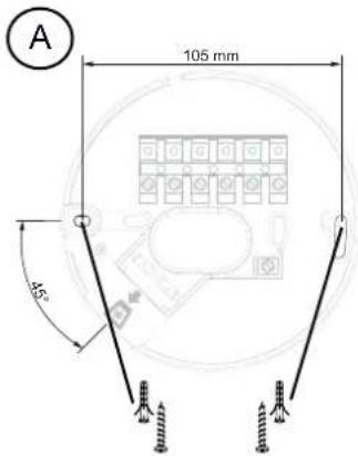
Fig./Abb./Obr. 4 Fig./Abb./Obr. 5
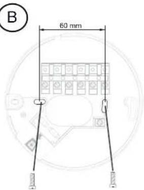
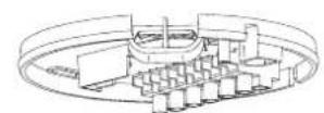
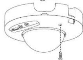
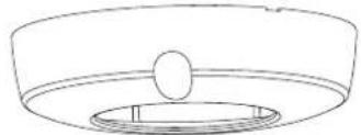
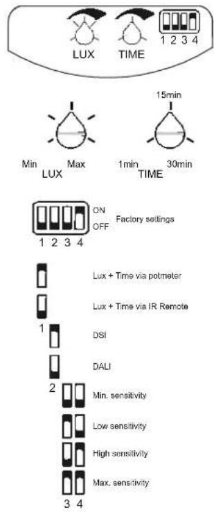
Fig./Abb./Obr. 6
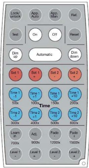
Fig./Abb./Obr. 8
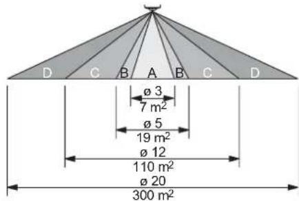
Fig./Abb./Obr. 7
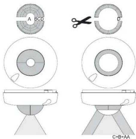
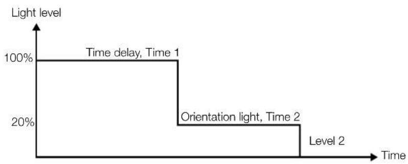
Fig./Abb./Obr. 9
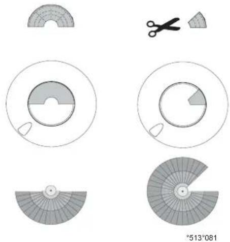
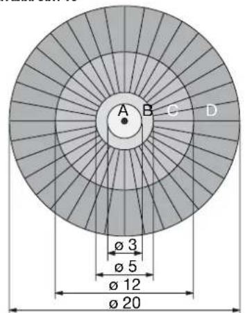
Fig./Abb./Obr. 10