
HTT 5 - Hand dryer STIEBEL ELTRON - Free user manual and instructions
Find the device manual for free HTT 5 STIEBEL ELTRON in PDF.
| Product type | Automatic infrared sensor hand dryer |
| Brand and model | Stiebel Eltron HTT 5 |
| Dimensions (H x W x D) | 266 x 257 x 230 mm |
| Weight | 4.2 kg (die-cast aluminum housing) |
| Power supply | 1/N ~ 220-240 V 50/60 Hz |
| Rated power | 2600 W |
| Heating power | 2500 W |
| Blower power | 100 W |
| Protection class | II |
| Protection rating | IP 23 |
| Noise level | ~ 54 dB(A) |
| Airflow rate | ~ 146 m³/h |
| Drying time | ~ 36 seconds |
| Detection range | 4 to 13 cm below the air outlet grille |
| Automatic shut-off | ~ 3 seconds after hands removed |
| Housing material | Lacquered die-cast aluminum (HTT 5) |
| Available colors | Metallic anthracite, metallic silver |
| Mounting type | Wall-mounted, screw fixing (4 points) |
| Recommended mounting height | 1250 mm (woman) to 1350 mm (man) from floor |
| Maintenance | Clean with a damp cloth, without abrasive products or solvents |
| Overheat protection | Heater cuts off in case of overheating, blower continues for cooling |
| Warranty | Varies by distribution country (refer to local terms) |
| Included accessories | Drilling template, user and installation manual |
Frequently Asked Questions - HTT 5 STIEBEL ELTRON
User questions about HTT 5 STIEBEL ELTRON
0 question about this device. Answer the ones you know or ask your own.
Ask a new question about this device
Download the instructions for your Hand dryer in PDF format for free! Find your manual HTT 5 - STIEBEL ELTRON and take your electronic device back in hand. On this page are published all the documents necessary for the use of your device. HTT 5 by STIEBEL ELTRON.
USER MANUAL HTT 5 STIEBEL ELTRON
BEDIENUNG UND INSTALLATION OPERATION AND INSTALLATION UTILISATION ET INSTALLATION BEDIENING EN INSTALLATIE OPERAÇÃO E INSTALAÇÃO OBSŁUGA I INSTALACJA OBSLUHA A INSTALACE KEZELÉS ÉS TELEPÍTÉS ЭКСПЛУАТАЦИЯ И МОНТАЖ
HÄNDETROCKNER | HAND DRYER | SÈCHE-MAINS | HANDENDROGER | SECADOR DE MÃOS | SUSZARKA DO RÂK | SUŠIČ RUKOU | KÉZSZÁRÍTÓ | ЭЛЕКТРИЧЕСКИЕ СУШИЛКИ ДЛЯ РУК
» H T T 4
» H T T 5
natural_image
Simple line drawing of a person standing at a desk with a monitor, no text or symbols presentSTIEBEL ELTRON
BEDIENUNG 2
1 Kunstoffwinkel
natural_image
Pure 3D grid lines with a central shaded rectangular region and a small circular symbol, no text or labels present.natural_image
Technical line drawing of a mechanical device with grid background and measurement annotations (no readable text or symbols)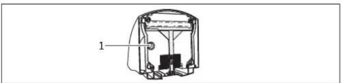
natural_image
Technical line drawing of a mechanical device with labeled component (no text or symbols present)1 Kabeldurchführung
natural_image
Illustration of a hand holding a device with an arrow indicating rotation, accompanied by a magnified inset showing mechanical components (no text or symbols)26_07_32_0028
natural_image
Illustration of a hand holding a device with an inset showing a mechanical component (no text or symbols)26_07_32_0029
- General information 12
1.1 Document information
1.2 Key to symbols 12 - Safety ____
2.1 Intended use 13
2.2 Safety information 13
2.3 CE designation 13
2.4 Test symbols 13 - Equipment description
- Operation
- Cleaning, care and maintenance 14
- What to do if ... 14
6.1 ... the appliance does not start 14
6.2 ... the fan is running but there is no hot air 14
6.3 The type plate 14
INSTALLATION 15
- Safety 15
7.1 General safety instructions 15
7.2 Instructions, standards and regulations ____ 15 - Installation 15
8.1 Installation information 15
8.2 Installation conditions and preparations 15
8.3 Power supply 15 - Installation 15
9.1 Removing the HTT 4 casing cover 15
9.2 Removing the HTT 5 casing cover ____ 15
9.3 Wall mounting 16
9.4 Fitting the HTT 4 casing cover 16
9.5 Fitting the HTT 5 casing cover ____ 16 - Appliance handover 16
- Specification 17
11.1 Specification 17
11.2 Wiring diagram 18
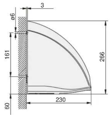
11.3 Clearances 18
11.4 Guidelines for installation height 18
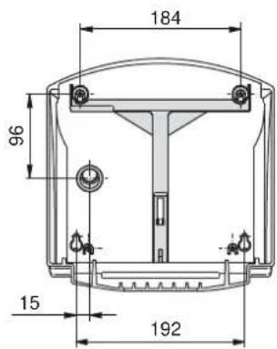
11.5 Dimensions 19
CUSTOMER SERVICE AND WARRANTY 20
ENVIRONMENT AND RECYCLING 20
1. General information
1.1 Document information
The chapter Operation is intended for users and contractors.
13 The chapter Installation is intended for heating contractors.

Please read
Read these instructions carefully before using the appliance and retain them for future reference. Pass on the instructions, if required, to a new user.
^14 1.2 Key to symbols
Symbols in this documentation:
In these instructions you will come across symbols and highlights.
These have the following meaning:

Risk of injury!
Information concerning possible risk of injury.

Danger of electrocution!

Risk of burning!

Fire hazard!

Never cover!

Possible damage
Information concerning damage to the appliance, environmental damage or material losses.

Note!
Text next to this symbol is particularly important.
» The "»" symbol indicates that you should do something. The action you need to take is described step by step.
2. Safety
2.1 Intended use
The appliance is used to dry wet hands.
Any other use beyond that described shall be deemed inappropriate. Observation of these instructions is also part of the correct use of this appliance. Any modifications or conversions to the appliance void all warranty rights.
2.2 Safety information

Risk of burning!
During operation, temperatures in excess occur at the hot air outlet.

Risk of burning!
Where children or persons with limited physical, sensory or mental capabilities are to be allowed to control this appliance, ensure that this will only happen under supervision or after appropriate instructions by a person responsible for their safety. Children must be supervised to ensure that they never play with the appliance.

Fire hazard!
Never place any objects on top of the appliance. Never lean any objects against it or place any objects between the appliance and the wall.
Never place any flammable, combustible or insulating objects or materials, such as laundry, blankets, magazines, containers with floor polish or napsan, spray cans or similar, in direct proximity of the appliance.

Fire hazard!
Never operate this appliance ...
... in rooms where the appliance is at risk from fire or explosion as a result of chemicals, dust, gases or vapours.
... in the direct proximity of pipes or receptacles that carry or contain flammable or explosive materials.
... if work such as laying cables, grinding or sealing is carried out in the installation room.
... if sprays, floor polish or similar products containing napsan are used. Ensure the room is adequately ventilated before using the appliance.

Danger of electrocution!
Never insert any objects into any aperture in the appliance. This can lead to fatal electric shocks and / or fires.

Never cover!
Never cover the appliance to prevent overheating.

Note!
Never operate the appliance if the minimum clearances to adjacent surfaces are not maintained.

Note!
If you use the appliance in workshops or other rooms where flue gases, oil and petrol vapours, etc. are present, or solvents and chemicals are used, lasting, unpleasant odours and possibly contamination can result.

Note!
Ensure that the air inlet aperture at the bottom and back of the appliance is always open.

Note!
Maintain the minimum clearance (see chapter Specification) to the air outlet grille at the bottom. The hot air must be able to escape unimpeded.

Note!
Never spray the appliance with a water hose to clean it (see chapter Cleaning, care and maintenance).
2.3 CE designation
The CE designation shows that the appliance meets all essential requirements according to the:
– Electromagnetic Compatibility Directive
-Low Voltage Directive
2.4 Test symbols
See type plate.
3. Equipment description
The appliance works without contact. It is fitted with an optical proximity sensor, which automatically activates the heater and fan when your hands approach the appliance. The response area is between 4 cm and 13 cm beneath the air outlet grille. When you remove your hands, the appliance stops after approx. three seconds.
The casing design makes it virtually impossible to use the appliance as a depository for cigarettes or similar. Avoid any wall offset at the top of the appliance to maintain this effect.
The HTT 5 is also protected against damage by its robust diecast aluminium casing.
4. Operation
» Shake your wet hands over the sink before drying. This reduces the drying time and saves energy.
» Then hold your hands under the air outlet grille and rub them together in the hot air current.
5. Cleaning, care and maintenance
A damp cloth is sufficient for cleaning the casing. Never use abrasive or corrosive cleaning agents. Go over the casing with a soft cloth. Never spray the appliance using a water hose or other tools. This would let water penetrate the appliance.
6. What to do if ...
6.1 ... the appliance does not start
-Check the fuses / MCBs in your fuse box.
- Covering the optical proximity sensor impairs the function of the appliance. In this case, the appliance stops after approx. three seconds to avoid constant operation. In the event of a fault, check whether the sensor surface is clear. Once you have removed any objects, the appliance will work correctly again.
6.2 ... the fan is running but there is no hot air
- When overheating occurs, the heater bank is switched off but the fan continues to run for cooling purposes. The temperature sensor switches the heater on again approx. two minutes after the appliance stops.
6.3 The type plate
The type plate is located at the bottom of the appliance.
7. Safety
Only qualified contractors should carry out installation, commissioning, maintenance and repair of the appliance.
7.1 General safety instructions
We guarantee trouble-free operation and operational reliability only if the original accessories and spare parts intended for the appliance are used.
7.2 Instructions, standards and regulations

Note!
Observe all applicable national and regional regulations and instructions.

Note!
When installing the appliance in rooms with a bath and / or shower, take the relevant safety zone into account. Install the appliance in accordance with the information on the type plate. Refer to VDE 0100 - 701 for the standard applicable to safety zones in Germany.
8. Installation
8.1 Installation information
-Fit the appliance flat against a solid wall (without any offset) to prevent damage caused by vandalism.
8.2 Installation conditions and preparations
- Always fit the appliance to a vertical wall that is temperature-resistant to over 90 °C.
- Always maintain the specified minimum clearances.
8.3 Power supply

Note!
Observe the type plate. The specified voltage must match the mains voltage.

Danger of electrocution!
Only use a permanent connection to the power supply. The appliance must be able to be separated from the mains power supply by an isolator that disconnects all poles with at least 3 mm contact separation.
» Select a power cable with an adequate cross-section.
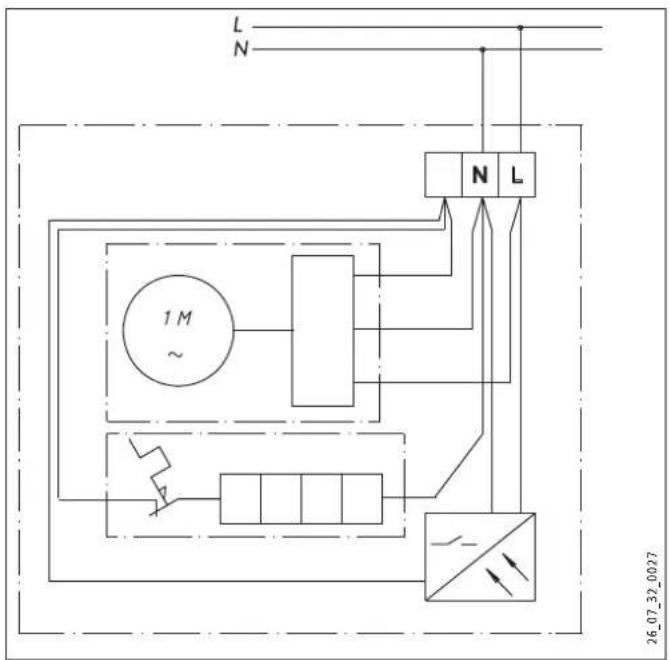
» Connect the power cable in accordance with the wiring diagram (see Specification).
1 Plastic bracket
The plastic bracket fixed to the inside of the HTT 5 casing cover provides additional insulation for the power cable and terminal.
9. Installation

Danger of electrocution!
Carry out all electrical connection and installation work in accordance with relevant regulations.
9.1 Removing the HTT 4 casing cover
1 Casing cover
2 Locking slide
3 Screws
» Undo the screws on the casing cover and locking slide.
» Pull the locking slide down.
» Remove the casing cover.
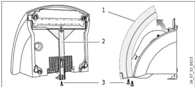
9.2 Removing the HTT 5 casing cover
» Undo the locking screw.
» Pull the locking slide down.
» Remove the casing cover.
1 Casing cover
2 Locking slide
3 Locking screw
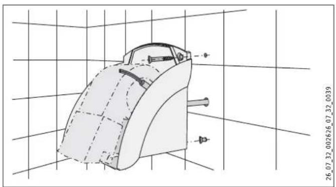
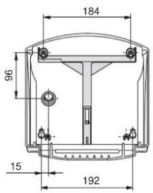
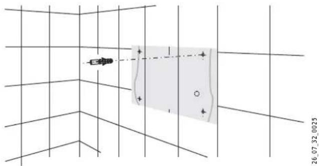
9.3 Wall mounting

» Cut out the drilling template. This can be found at the end of these instructions.
» Transfer the four mounting points on to the wall using the drilling template. Pay attention to the length and position of the power cable. Use our height guidelines to help you (see Specification).
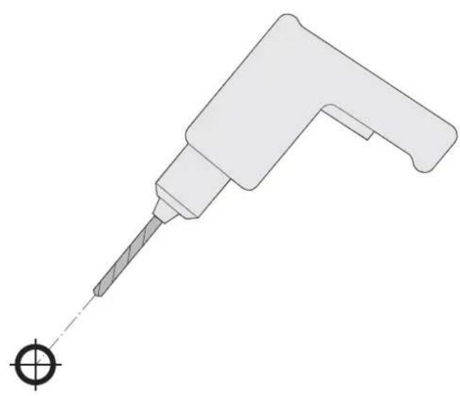
» Drill the fixing holes and insert rawl plugs.
» Insert the lower fixing screws into the wall.
natural_image
Technical line drawing of a mechanical component with grid background and measurement annotations (no readable text or symbols)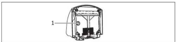
natural_image
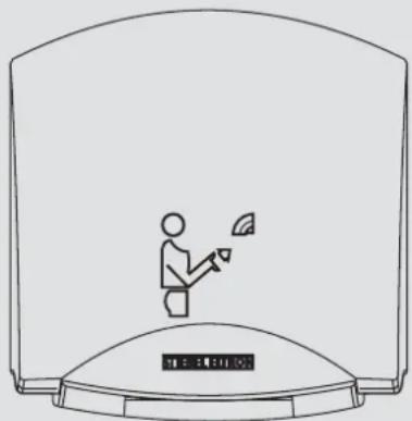
Technical line drawing of a mechanical device with labeled component (no text or symbols present)1 Cable entry
» Pull the power cable through the cable entry in the back panel of the appliance.
» Fit the appliance with the keyhole fixings on to the fixing screws.
» Secure the appliance to the wall using two more screws.
» Connect the power cable to the appliance.

Note!
Ensure that the wires of the power cable are not near the fan motor.

Note!
Observe the maximum length of the power cable. (See Specification)
9.4 Fitting the HTT 4 casing cover
natural_image
Illustration of a hand holding a device with an inset showing a mechanical component (no text or symbols)» Place the casing cover on the appliance so that it is slightly tilted and pivot it towards the wall.
» Push the locking slide up as far as it will go.
» Secure the locking slide and the casing cover with screws.
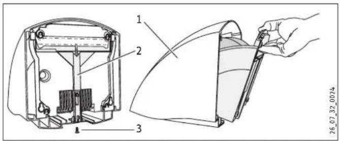
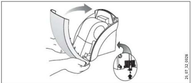
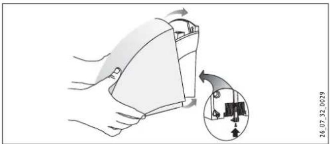
9.5 Fitting the HTT 5 casing cover
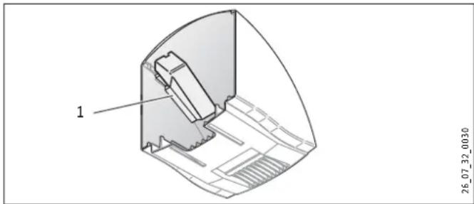
natural_image
Illustration of a hand holding a device with an inset showing a mechanical component (no text or symbols)» Slide the casing cover, slightly tilted, over the appliance towards the wall as far as it will go. Ensure that the hooks provided on the bottom of the casing cover catch behind the back panel of the appliance.
» To lock in place, lift the casing cover slightly at the front and push the locking slide up as far as it will go.
» Secure the locking slide with screws.
10. Appliance handover
Explain the functions of the appliance to the user. Draw special attention to the safety information. Hand the operating and installation instructions to the user.
11. Specification
11.1 Specification
| Model Hand dryer | |||||
| Type | HTT 4 WS turbotronic | HTT 5 WS turbotronic | HTT 5 AM turbotronic | HTT 5 SM turbotronic | |
| Part number 074464 074465 | 182052 182053 | ||||
| Colour | alpine white | signal white | anthracite metallic | silver metallic | |
| Casing | Plastic (ABS) | Diecast aluminium, painted | Diecast aluminium, painted | Diecast aluminium, painted | |
| Operating details | |||||
| Rated output | W | 2600 | 2600 | 2600 | 2600 |
| Output | W | 2500 | 2500 | 2500 | 2500 |
| Fan power | W | 100 | 100 | 100 | 100 |
| Connection | 1/N 220-240 V 50/60 Hz | 1/N 220-240 V 50/60 Hz | 1/N 220-240 V 50/60 Hz | 1/N 220-240 V 50/60 Hz | |
| Protection cat. to EN 60335 | II | II | II | II | |
| Protection | IP 23 | IP 23 | IP 23 | IP 23 | |
| Operating noise | ~ dB (A) | 68 | 68 | 68 | 68 |
| Air throughput | ~ m3/h | 250 | 250 | 250 | 250 |
| Runtime | s | 20 | 20 | 20 | 20 |
| Dimensions and weights | |||||
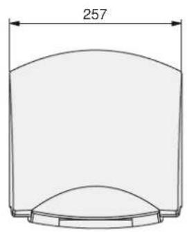
| Dimensions H x W x D | mm | 250 x 238 x 230 | 266 x 257 x 230 | 266 x 257 x 230 | 266 x 257 x 230 |
| Weight | kg | 2,7 | 4,2 | 4,2 | 4,2 |
| Maximum length of the power cable | mm | 200 | 200 | 200 | 200 |
11.2 Wiring diagram
11.3 Clearances
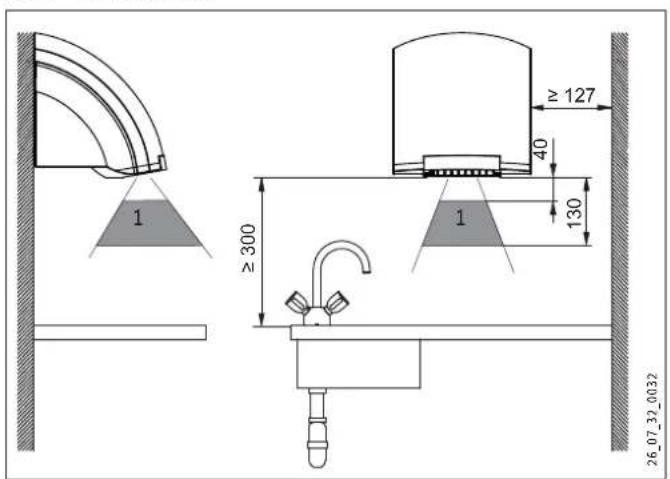
1 Detection range of IR proximity sensor
11.4 Guidelines for installation height

Note! Height (mm) indicates the clearance between the bottom of the appliance and the floor.
Age Age Height (mm)

Adult man 1350

Adult woman 1250

Nursery school age 4 - 7 810

Primary school age 7 - 10 910

Middle school age 10 - 13 1120

High school age 13 - 16 1250
11.5 Dimensions
11.5.1 HTT 4
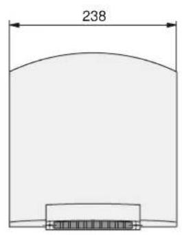
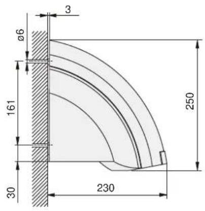
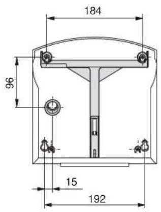
11.5.2 HTT 5
Warranty
The warranty conditions of our German companies do not apply to appliances acquired outside of Germany. In countries where our subsidiaries sell our products, it is increasingly the case that warranties can only be issued by those subsidiaries. Such warranties are only granted if the subsidiary has issued its own terms of warranty. No other warranty will be granted.
We shall not provide any warranty for appliances acquired in countries where we have no subsidiary to sell our products. This will not affect warranties issued by any importers.
Environment and recycling
We would ask you to help protect the environment. After use, dispose of the various materials in accordance with national regulations.
UTILISATION 21
1 Equerre plastique
natural_image
Diagram showing a vehicle moving in a grid with a shaded rectangular area and coordinate label (no text or symbols on the diagram itself)natural_image
Technical line drawing of a mechanical component with grid background (no text or symbols)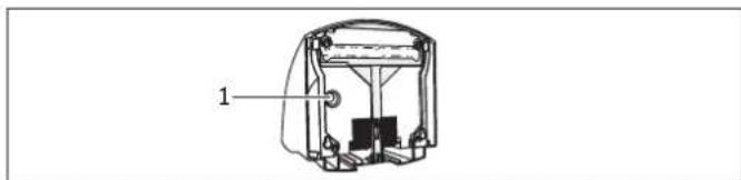
1 Passe-câble
natural_image
Illustration of a hand holding a device with an arrow indicating rotation, showing internal components and a magnified inset (no text or symbols)natural_image
Illustration of a hand holding a device with an inset showing a mechanical component (no text or symbols)natural_image
Simple line drawing of a cylindrical container with a curved top and bottom base, labeled with dimension 257 (no text or symbols beyond the label)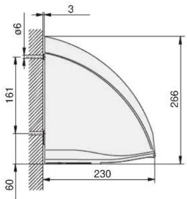
Garantie
1 Kunststofhoek
1 Behuizingskap
2 Vergrendelingschuif
3 Schroeven
natural_image
Technical line drawing of a mechanical component with grid background (no text or symbols)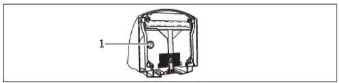
1 Kabeldoorvoer
natural_image
Illustration of a hand holding a device with a magnified inset showing internal components (no text or symbols)natural_image
Technical line drawing of a mechanical component with grid background (no text or symbols)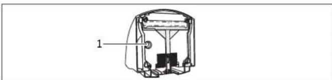
natural_image
Technical line drawing of a mechanical device with labeled component (1), no readable text or symbols present1 Passagem do cabo
natural_image
Illustration of a hand holding a device with an inset showing a mechanical component (no text or symbols)natural_image
Illustration of a hand holding a device with an inset showing a mechanical component (no text or symbols)natural_image
Technical line drawing of a mechanical component with grid background (no text or symbols)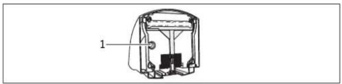
1 Przelot kabla
natural_image
Illustration of a hand holding a device with a magnified inset showing internal components (no text or symbols)natural_image
Illustration of a hand holding a device with a magnified inset showing internal components (no text or symbols)1 Plastový úhelník
1 Kryt prístroje
2 Blokovací lišta
3 Blokovací šroub
9.3 Montáž na stěnu
natural_image
Technical line drawing of a mechanical component with grid background (no text or symbols)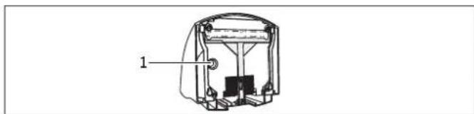
natural_image
Illustration of a hand holding a device with an arrow indicating rotation, showing internal components and a magnified inset (no text or symbols)natural_image
Illustration of a hand holding a medical device with an inset showing internal components (no text or symbols)1 Múanyag sarokelem
natural_image
Diagram showing a device positioned at a grid with a shaded rectangular area and coordinate label (no readable text or symbols)natural_image
Technical line drawing of a mechanical component with grid background (no text or symbols)
natural_image
Technical line drawing of a mechanical device with labeled component (1), no readable text or symbols present1 Kábelátvezetés
natural_image
Illustration of a hand holding a device with a magnified inset showing internal components (no text or symbols)natural_image
Technical diagram of a mechanical component with labeled part '1' and reference number 26_07_32_0030 (no readable text or symbols beyond labels)natural_image
Technical line drawing of a mechanical component with grid background and measurement annotations (no readable text or symbols)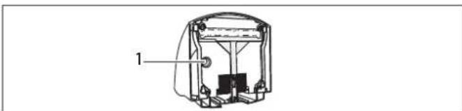
natural_image
Technical line drawing of a mechanical device with labeled component (1), no readable text or symbols present1 Кабельный ввод
natural_image
Illustration of a hand holding a device with an arrow indicating rotation, alongside a magnified inset showing a mechanical component (no text or symbols)26 07 32 0028
natural_image
Illustration of a hand holding a device with a magnified inset showing a mechanical component (no text or symbols)26 07 32 0029
natural_image
Simple line drawing of a cylindrical container with a curved top and bottom base, labeled with dimension 257 (no text or symbols beyond the label)

Гарантия
natural_image
Illustration of scissors cutting through a dashed circle with a lightning bolt symbol (no text or labels)
natural_image
Technical illustration of a mechanical tool with a pointed tip and circular base (no text or symbols)
Deutschland
Urzhumskaya street 4,
building 2 | 129343 Moscow
Tel. 0495 7753889 | Fax 0495 7753887
info@stiebel-eltron.ru
www.stiebel-eltron.ru
Slovakia
TATRAMAT - ohrievače vody, s.r.o.
Hlavná 1 | 058 01 Poprad
Tel. 052 7127-125 | Fax 052 7127-148
info@stiebel-eltron.sk
www.stiebel-eltron.sk
Switzerland
STIEBEL ELTRON AG
Industrie West
Gass 8 | 5242 Lupfig
Tel. 056 4640-500 | Fax 056 4640-501
info@stiebel-eltron.ch
www.stiebel-eltron.ch
Thailand
STIEBEL ELTRON Asia Ltd.
469 Moo 2 Tambol Klong-Jik
Amphur Bangpa-In | 13160 Ayutthaya
Tel. 035 220088 | Fax 035 221188
info@stiebeleltronasia.com
www.stiebeleltronasia.com
United Kingdom and Ireland
STIEBEL ELTRON UK Ltd.
Unit 12 Stadium Court
Stadium Road | CH62 3RP Bromborough
Tel. 0151 346-2300 | Fax 0151 334-2913
info@stiebel-eltron.co.uk
www.stiebel-eltron.co.uk
United States of America
STIEBEL ELTRON, Inc.
17 West Street | 01088 West Hatfield MA
Tel. 0413 247-3380 | Fax 0413 247-3369
info@stiebel-eltron-usa.com
www.stiebel-eltron-usa.com

Irrtum und technische Änderungen vorbehalten! | Subject to errors and technical changes! | Sous réserve d'erreurs et de modifications techniques! | Onder voorbehoud van vergissingen en technische wijzigingen! | Salvo error o modificación técnica! | Excepto erro ou alteração técnica | Zastrzezone zmian techniczne i ewentualne blijy! | Omyly a technické zmény isou whrazený! | A muszaki változtalások és tévedések jogát fenntartjuk! | Отсутствие ошибok ne гарантируется. Возможны технические изменения. | Chyby a technické zmény sú wyhradené! Stand 8770
STIEBEL ELTRON
- BEDIENUNG 2
- Kunstoffwinkel
- INSTALLATION 15
- CUSTOMER SERVICE AND WARRANTY 20
- ENVIRONMENT AND RECYCLING 20
- General information
- Document information
- 1.2 Key to symbols
- Safety
- Intended use
- Safety information
- CE designation
- Test symbols
- Equipment description
- Operation
- Cleaning, care and maintenance
- What to do if ...
- ... the appliance does not start
- ... the fan is running but there is no hot air
- The type plate
- Safety
- General safety instructions
- Instructions, standards and regulations
- Installation
- Installation information
- Installation conditions and preparations
- Power supply
- Installation
- Removing the HTT 4 casing cover
- Removing the HTT 5 casing cover
- Appliance handover
- Specification
- Guidelines for installation height
- Dimensions
- Warranty
- Environment and recycling
- UTILISATION 21
- Passe-câble
- Garantie
- Kábelátvezetés
- Кабельный ввод
- Гарантия
- Deutschland
- Slovakia
- Switzerland
- Thailand
- United Kingdom and Ireland
- United States of America
Brand : STIEBEL ELTRON
Model : HTT 5
Category : Hand dryer