
RP1110CJ - Milling machine MAKITA - Free user manual and instructions
Find the device manual for free RP1110CJ MAKITA in PDF.

| Brand | Makita |
| Model | RP1110CJ |
| Product Type | Router (plunge router) |
| Collet Capacity | 8 mm or 1/4" |
| Plunge Depth | 0-57 mm |
| No Load Speed | 8,000 - 24,000 min⁻¹ (variable, 5 positions) |
| Overall Height | 260 mm |
| Net Weight | 3.4 kg (according to EPTA 01/2003) |
| Power Supply | Single-phase, mains voltage (see rating plate) |
| Double Insulation | Yes, compliant with European regulations (no earthing required) |
| Application | Flush trimming, profiling of wood, plastic and similar materials |
| Depth of Cut Adjustment | By stop rod with indicator and adjustment knob (1 mm per turn) |
| 3-Stop Turret | Three hexagon adjusting bolts (0.8 mm/turn) for preset depths |
| Variable Speed Control | Dial from 1 to 5, select ideal speed according to material and bit diameter |
| Straight Guide | Attached to the base for straight cuts, adjustable distance |
| Templet Guide (accessory) | Allows use of templets for patterns |
| Dust Extraction Connection | Via ejector assembly and extraction adaptor (28 mm hose) |
| Maintenance | Carbon brush replacement (check regularly, replace in pairs) |
| Safety | Wear hearing protection recommended; follow general and specific safety instructions |
Frequently Asked Questions - RP1110CJ MAKITA
User questions about RP1110CJ MAKITA
0 question about this device. Answer the ones you know or ask your own.
Ask a new question about this device
Download the instructions for your Milling machine in PDF format for free! Find your manual RP1110CJ - MAKITA and take your electronic device back in hand. On this page are published all the documents necessary for the use of your device. RP1110CJ by MAKITA.
USER MANUAL RP1110CJ MAKITA
| Explanation of general view | ||
| 1 Adjusting knob | 15 Wrench | 29 Bit |
| 2 Stopper pole | 16 Shaft lock | 30 Base |
| 3 Depth pointer | 17 Tighten | 31 Templet |
| 4 Stopper pole setting nut | 18 Loosen | 32 Workpiece |
| 5 Lock knob | 19 Correct size collet cone | 33 Distance (X) |
| 6 Fast-feed button | 20 Workpiece | 34 Outside diameter of the templet guide |
| 7 Adjusting hex bolt | 21 Bit revolving direction | |
| 8 Stopper block | 22 Feed direction | 35 Nozzle assembly |
| 9 Nylon nut | 23 View from the top of the tool | 36 Dust nozzle assembly |
| 10 Hex nut | 24 Straight guide | 37 Limit mark |
| 11 Lock button | 25 Lock screw | 38 Brush holder cap |
| 12 Switch trigger | 26 Guiding surface | 39 Screwdriver |
| 13 Speed adjusting dial | 27 Templet guide | |
| 14 Collet nut | 28 Screw | |
SPECIFICATIONS
| Model | RP0910 | RP1110C | |
| Max. collet capacity | 8 mm or 1/4" | 8 mm or 1/4" | |
| Plunge capacity | 0 - 57 mm | 0 - 57mm | |
| No load speed (min-1) | 27,000 | 8,000 - 24,000 | |
| Overall height | 260 mm | 260 mm | |
| Net weight | 3.3 kg | 3.4 kg | |
| Safety class | /II /II | /II |
- Due to our continuing program of research and development, the specifications herein are subject to change without notice.
- Specifications may differ from country to country.
Weight according to EPTA-Procedure 01/2003
Intended use
The tool is intended for flush trimming and profiling of wood, plastic and similar materials.
Power supply
The tool should be connected only to a power supply of the same voltage as indicated on the nameplate, and can only be operated on single-phase AC supply. They are double-insulated in accordance with European Standard and can, therefore, also be used from sockets without earth wire.
GEA010-1
General Power Tool SafetyWarnings
WARNING Read all safety warnings and all instructions. Failure to follow the warnings and instructions may result in electric shock, fire and/or serious injury.
Save all warnings and instructions for future reference.
GEB018-2
ROUTER SAFETY WARNINGS
- Hold power tool by insulated gripping surfaces when performing an operation where the cutting tool may contact hidden wiring or its own cord. Contact with a "live" wire will make exposed metal parts of the tool "live" and shock the operator.
- Use clamps or another practical way to secure and support the workpiece to a stable platform. Holding the work by hand or against your body leaves it unstable and may lead to loss of control.
-
Wear hearing protection during extended period of operation.
-
Handle the bits very carefully.
- Check the bit carefully for cracks or damage before operation. Replace cracked or damaged bit immediately.
- Avoid cutting nails. Inspect for and remove all nails from the workpiece before operation.
- Hold the tool firmly with both hands.
- Keep hands away from rotating parts.
- Make sure the bit is not contacting the workpiece before the switch is turned on.
- Before using the tool on an actual workpiece, let it run for a while. Watch for vibration or wobbling that could indicate improperly installed bit.
- Be careful of the bit rotating direction and the feed direction.
- Do not leave the tool running. Operate the tool only when hand-held.
- Always switch off and wait for the bit to come to a complete stop before removing the tool from workpiece.
- Do not touch the bit immediately after operation; it may be extremely hot and could burn your skin.
- Do not smear the tool base carelessly with thinner, gasoline, oil or the like. They may cause cracks in the tool base.
- Draw attention to the need to use cutters of the correct shank diameter and which are suitable for the speed of the tool.
- Some material contains chemicals which may be toxic. Take caution to prevent dust inhalation and skin contact. Follow material supplier safety data.
- Always use the correct dust mask/respirator for the material and application you are working with.
SAVE THESE INSTRUCTIONS.
WARNING:
DO NOT let comfort or familiarity with product (gained from repeated use) replace strict adherence to safety rules for the subject product. MISUSE or failure to follow the safety rules stated in this instruction manual may cause serious personal injury.
FUNCTIONAL DESCRIPTION
CAUTION:
- Always be sure that the tool is switched off and unplugged before adjusting or checking function on the tool.
Adjusting the depth of cut (Fig. 1)
Place the tool on a flat surface. Loosen the lock knob and lower the tool body until the bit just touches the flat surface. Tighten the lock knob to lock the tool body.
Turn the stopper pole setting nut counterclockwise. Lower the stopper pole until it makes contact with the adjusting bolt. Align the depth pointer with the "0" graduation. The depth of cut is indicated on the scale by the depth pointer.
While pressing the fast-feed button, raise the stopper pole until the desired depth of cut is obtained. Minute depth adjustments can be obtained by turning the adjusting knob (1 mm per turn.)
By turning the stopper pole setting nut clockwise, you can fasten the stopper pole firmly.
Now, your predetermined depth of cut can be obtained by loosening the lock knob and then lowering the tool body until the stopper pole makes contact with the adjusting bolt of the stopper block.
Nylon nut (Fig. 2)
By turning the nylon nut, the upper limit of the tool body can be adjusted. When the tip of the bit is retracted more than required in relation to the base plate surface, turn the nylon nut to lower the upper limit.
CAUTION:
- Since excessive cutting may cause overload of the motor or difficulty in controlling the tool, the depth of cut should not be more than 15mm at a pass when cutting grooves with an 8mm diameter bit.
- When cutting grooves with a 20mm diameter bit, the depth of cut should not be more than 5mm at a pass.
- For extra-deep grooving operations, make two or three passes with progressively deeper bit settings.
- Do not lower the nylon nut too low or the bit will protrude dangerously.
Stopper block (Fig. 3)
The stopper block has three adjusting hex bolts which raise or lower 0.8mm per turn. You can easily obtain three different depths of cut using these adjusting hex bolts without readjusting the stopper pole.
Adjust the lowest hex bolt to obtain the deepest depth of cut, following the method of "Adjusting depth of cut". Adjust the two remaining hex bolts to obtain shallower depths of cut. The differences in height of these hex bolts are equal to the differences in depths of cut.
To adjust the hex bolts, first loosen the hex nuts on the hex bolts with the wrench and then turn the hex bolts. After obtaining the desired position, tighten the hex nuts while holding the hex bolts in that desired position. The stopper block is also convenient for making three passes with progressively deeper bit settings when cutting deep grooves.
Switch action (Fig. 4)
CAUTION:
- Before plugging in the tool, always check to see that the switch trigger actuates properly and returns to the "OFF" position when released.
- Make sure that the shaft lock is released before the switch is turned on.
To start the tool, depress the lock button and pull the switch trigger. Release the switch trigger to stop.
For continuous operation, pull the switch trigger and then depress the lock button further. To stop the tool, pull the switch trigger so that the lock button returns automatically. Then release the switch trigger.
After releasing the switch trigger, the lock-off function works to prevent the switch trigger from being pulled.
Speed adjusting dial (Fig. 5)
For RP1110C
The tool speed can be changed by turning the speed adjusting dial to a given number setting from 1 to 5.
Higher speed is obtained when the dial is turned in the direction of number 5. And lower speed is obtained when it is turned in the direction of number 1.
This allows the ideal speed to be selected for optimum material processing, i.e. the speed can be correctly adjusted to suit the material and bit diameter.
Refer to the table for the relationship between the number settings on the dial and the approximate tool speed.
| Number min | -1 |
| 1 8,000 | |
| 2 12,000 | |
| 3 16,000 | |
| 4 20,000 | |
| 5 24,000 |
CAUTION:
- The speed adjusting dial can be turned only as far as 5 and back to 1. Do not force it past 5 or 1, or the speed adjusting function may no longer work.
ASSEMBLY
CAUTION:
- Always be sure that the tool is switched off and unplugged before carrying out any work on the tool.
Installing or removing the bit (Fig. 6 & 7)
CAUTION:
- Install the bit securely. Always use only the wrench provided with the tool. A loose or overtightened bit can be dangerous.
- Do not tighten the collet nut without inserting a bit. It can lead to breakage of the collet cone.
Insert the bit all the way into the collet cone. Press the shaft lock to keep the shaft stationary and use the wrench to tighten the collet nut securely.
A 8 mm or 6.35 mm collet cone is factory installed on the tool. When using router bits with other shank diameter, use the correct size collet cone for the bit which you intend to use.
To remove the bit, follow the installation procedure in reverse.
OPERATION
CAUTION:
- Before operation, always make sure that the tool body automatically rises to the upper limit and the bit does not protrude from the tool base when the lock knob is loosened.
Set the tool base on the workpiece to be cut without the bit making any contact. Then turn the tool on and wait until the bit attains full speed. Lower the tool body and move the tool forward over the workpiece surface, keeping the tool base flush and advancing smoothly until the cutting is complete.
When doing edge cutting, the workpiece surface should be on the left side of the bit in the feed direction. (Fig. 8)
NOTE:
- Make sure that the dust guide is installed properly.
- Moving the tool forward too fast may cause a poor quality of cut, or damage to the bit or motor. Moving the tool forward too slowly may burn and mar the cut. The proper feed rate will depend on the bit size, the kind of workpiece and depth of cut. Before beginning the cut on the actual workpiece, it is advisable to make a sample cut on a piece of scrap lumber. This will show exactly how the cut will look as well as enable you to check dimensions.
- When using the straight guide, be sure to install it on the right side in the feed direction. This will help to keep it flush with the side of the workpiece. (Fig. 9)
Straight guide (Fig. 10, 11& 12)
The straight guide is effectively used for straight cuts when chamfering or grooving.
To install the straight guide, insert the guide bars into the holes in the tool base. Adjust the distance between the bit and the straight guide. At the desired distance, tighten the lock screw to secure the straight guide in place.
When cutting, move the tool with the straight guide flush with the side of the workpiece.
If the distance between the side of the workpiece and the cutting position is too wide for the straight guide, or if the side of the workpiece is not straight, the straight guide cannot be used. In this case, firmly clamp a straight board to the workpiece and use it as a guide against the router base. Feed the tool in the direction of the arrow.
Templet guide (Accessory) (Fig. 13, 14 &15)
The templet guide provides a sleeve through which the bit passes, allowing use of the tool with templet patterns. To install the templet guide, loosen the screws on the tool base, insert the templet guide and then tighten the screws.
Secure the templet to the workpiece. Place the tool on the templet and move the tool with the templet guide sliding along the side of the templet.
NOTE:
- The workpiece will be cut a slightly different size from the templet. Allow for the distance (X) between the bit and the outside of the templet guide. The distance (X) can be calculated by using the following equation:
Distance (X) = (outside diameter of the templet guide - bit diameter) / 2
Connecting to Makita vacuum cleaner (Fig. 16)
Cleaner operations can be performed by connecting the tool to Makita vacuum cleaner.
Insert the nozzle assembly and the dust nozzle assembly into the tool. Also, the dust nozzle assembly can be inserted into the tool base directly in accordance with the operation.
When connecting to Makita vacuum cleaner (Model 407), an optional hose 28mm in inner diameter is necessary.
MAINTENANCE
CAUTION:
- Always be sure that the tool is switched off and unplugged before attempting to perform inspection or maintenance.
- Never use gasoline, benzine, thinner, alcohol or the like. Discoloration, deformation or cracks may result.
Replacing carbon brushes
Remove and check the carbon brushes regularly. Replace when they wear down to the limit mark. Keep the carbon brushes clean and free to slip in the holders. Both carbon brushes should be replaced at the same time. Use only identical carbon brushes. (Fig. 17)
Use a screwdriver to remove the brush holder caps. Take out the worn carbon brushes, insert the new ones and secure the brush holder caps. (Fig. 18)
To maintain product SAFETY and RELIABILITY, repairs, any other maintenance or adjustment should be performed by Makita Authorized Service Centres, always using Makita replacement parts.
ACCESSIONS
CAUTION:
- These accessories or attachments are recommended for use with your Makita tool specified in this manual. The use of any other accessories or attachments might present a risk of injury to persons. Only use accessory or attachment for its stated purpose.
If you need any assistance for more details regarding these accessories, ask your local Makita Service Center.
- Straight & groove forming bits
- Edge forming bits
- Laminate trimming bits
- Straight guide
Templet guide 25 - Templet guides
- Lock nut
Collet cone 3 / 8" 1 / 4
Collet cone 6 mm, 8 mm
Wrench 8
Wrench 17 - Dust nozzle assembly
- Nozzle assembly
Noise
The typical A-weighted noise level determined according to EN60745:
For Model RP0910
Sound pressure level (L_pA) : 83 dB (A)
Sound power level (L_WA) : 94 dB (A)
Uncertainty (K): 3 dB (A)
For Model RP1110C
Sound pressure level (L_pA) : 81 dB (A)
Sound power level (L_WA) : 92 dB (A)
Uncertainty (K): 3 dB (A)
Wear ear protection
ENG223-2
Vibration
The vibration total value (tri-axial vector sum) determined according to EN60745:
For Model RP0910
Work mode: cutting grooves in MDF
Vibration emission (a_h) .. 8.0~m / s^2
Uncertainty (K): 1.5m / s^2
For Model RP1110C
Work mode: cutting grooves in MDF
Vibration emission (a_h) .. 5.0~m / s^2
Uncertainty (K): 1.5m / s^2
ENG901-1
- The declared vibration emission value has been measured in accordance with the standard test method and may be used for comparing one tool with another.
- The declared vibration emission value may also be used in a preliminary assessment of exposure.
WARNING:
- The vibration emission during actual use of the power tool can differ from the declared emission value depending on the ways in which the tool is used.
- Be sure to identify safety measures to protect the operator that are based on an estimation of exposure in the actual conditions of use (taking account of all parts of the operating cycle such as the times when the tool is switched off and when it is running idle in addition to the trigger time).
For European countries only
EC Declaration of Conformity
We Makita Corporation as the responsible manufacturer declare that the following Makita machine(s):
Designation of Machine:
Router
Electronic Router
Model No./ Type: RP0910, RP1110C
are of series production and
Conforms to the following European Directives:
98/37/EC until 28th December 2009 and then with 2006/42/EC from 29th December 2009
And are manufactured in accordance with the following standards or standardised documents:
EN60745
The technical documentation is kept by our authorized representative in Europe who is:
Makita International Europe Ltd.
Michigan Drive, Tongwell,
Milton Keynes, MK15 8JD, England
30th January 2009

Tomoyasu Kato
Director
Makita Corporation
3-11-8, Sumiyoshi-cho,
Anjo, Aichi, JAPAN
Descriptif
Michigan Drive, Tongwell,
Milton Keynes, MK15 8JD, Angleterre
30 janvier 2009

Tomoyasu Kato
Director
Makita Corporation
3-11-8, Sumiyoshi-cho,
Anjo, Aichi, JAPAN
Übersicht
Michigan Drive, Tongwell,
Milton Keynes, MK15 8JD, England
- Januar 2009

Tomoyasu Kato Direktor
Makita Corporation
3-11-8, Sumiyoshi-cho,
Anjo, Aichi, JAPAN
Visione generale
Modello No./Tip: RP0910, RP1110C
Michigan Drive, Tongwell,
Milton Keynes, MK15 8JD, England
30 gennaio 2009

Tomoyasu Kato
Amministratore
Makita Corporation
3-11-8, Sumiyoshi-cho,
Anjo, Aichi, JAPAN
Michigan Drive, Tongwell,
Milton Keynes, MK15 8JD, England
30 januari 2009

Tomoyasu Kato
Director
Makita Corporation
3-11-8, Sumiyoshi-cho,
Anjo, Aichi, JAPAN
Michigan Drive, Tongwell,
Milton Keynes, MK15 8JD, Inglaterra
30 de enero de 2009

Tomoyasu Kato Director
Makita Corporation
3-11-8, Sumiyoshi-cho,
Anjo, Aichi, JAPAN
Explicaçao geral
Michigan Drive, Tongwell,
Milton Keynes, MK15 8JD, Inglaterra
Tomoyasu Kato Director
Makita Corporation
3-11-8, Sumiyoshi-cho, Anjo, Aichi, JAPAN
2006/42/EC fra 29. December 2009
Michigan Drive, Tongwell,
Milton Keynes, MK15 8JD, England
- januar 2009

Tomoyasu Kato
Direktor
Makita Corporation
3-11-8, Sumiyoshi-cho,
Anjo, Aichi, JAPAN
Michigan Drive, Tongwell,
Milton Keynes, MK15 8JD, England (Ayyyia)
30 lavouapiou 2009

Tomoyasu Kato
△ieuθuvtns
Makita Corporation
3-11-8, Sumiyoshi-cho,
Anjo, Aichi, JAPAN
Router bits/Fraises de defonceuse/Fraser/Punte/Freesbits/Fresas/Brocas de freesadora/Frasevarktoj/ EpyaIeio nepoiotpEouevnC pdiIac
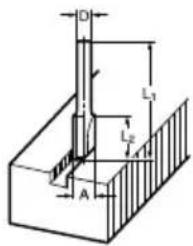
Straight bit Fraise à rainer Nutfräser Fresa a refilo Rechte frezen Fresa recta Fresa direita Notfæser Ioi Kɔπtɪkò
mm
| D | A | L1 | L2 | |
| 20 | 6 | 20 50 15 | ||
| 20E 1/4" | ||||
| 8 | 8 | 8 | ||
| 8 | 6 | 8 | 5 | 0 |
| 8E | 1/4" | |||
| 6 | 6 | 6 | 5 | 0 |
| 6E | 1/4" |
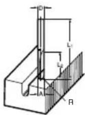
"U" Grooving bit
KoTikó yia auλakωμa "U"
mm
| D | A | L1 | L2 | R | |
| 6 | 6 | 6 | 60 | 28 | 3 |
| 6E | 1/4" |
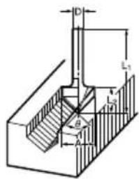
"V" Grooving bit
Drill point flush trimming bit
Fraise à affleurer Bündigfräser Fresa doppio refilo a punta
Drill point double flush trimming bit
Ball bearing beading bit
Ball bearing cove beading bit
Ball bearing roman ogee bit

- SPECIFICATIONS
- Intended use
- Power supply
- General Power Tool SafetyWarnings
- ROUTER SAFETY WARNINGS
- SAVE THESE INSTRUCTIONS.
- WARNING:
- FUNCTIONAL DESCRIPTION
- CAUTION:
- Adjusting the depth of cut (Fig. 1)
- Nylon nut (Fig. 2)
- Stopper block (Fig. 3)
- Switch action (Fig. 4)
- Speed adjusting dial (Fig. 5)
- For RP1110C
- ASSEMBLY
- Installing or removing the bit (Fig. 6 & 7)
- OPERATION
- NOTE:
- Straight guide (Fig. 10, 11& 12)
- Templet guide (Accessory) (Fig. 13, 14 &15)
- Connecting to Makita vacuum cleaner (Fig. 16)
- MAINTENANCE
- Replacing carbon brushes
- ACCESSIONS
- Noise
- For Model RP0910
- For Model RP1110C
- Wear ear protection
- Vibration
- For European countries only
- EC Declaration of Conformity
- We Makita Corporation as the responsible manufacturer declare that the following Makita machine(s):
- Conforms to the following European Directives:
- Tomoyasu Kato
- Director
- Descriptif
- Router bits/Fraises de defonceuse/Fraser/Punte/Freesbits/Fresas/Brocas de freesadora/Frasevarktoj/ EpyaIeio nepoiotpEouevnC pdiIac
Brand : MAKITA
Model : RP1110CJ
Category : Milling machine