MC 2.0 WL - Meter VDO - Free user manual and instructions
Find the device manual for free MC 2.0 WL VDO in PDF.



| Product type | Wireless bicycle computer |
| Brand | VDO |
| Model | MC 2.0 WL |
| Dimensions (computer) | Approx. 54 × 49 × 15 mm (H x W x D) |
| Weight (computer) | Approx. 45 g |
| Weight (mount) | Approx. 10 g |
| Power supply computer | 3 V battery, type 2032 |
| Battery life computer | Approx. 400 hours of operation (approx. 8000 km) |
| Power supply speed transmitter | 3 V battery, type 2032 |
| Operating temperature | -10 °C to +60 °C |
| Speed range | 2.0 to 116 km/h |
| Altitude range | -999 m to +4,999 m |
| Display | Liquid crystal display with backlight |
| Main functions | Speed, distance, time, altitude, elevation, heart rate, cadence, stopwatch, navigator, temperature |
| Bike compatibility | Up to 2 bikes with independent settings |
| Communication | Encoded digital wireless, max range 70 cm |
| Maintenance | Replace computer battery annually; clean with a soft cloth |
| Warranty | 3 years (excluding batteries, cables and mounting hardware) |
| Country of manufacture | Germany (Cycle Parts GmbH) |
Frequently Asked Questions - MC 2.0 WL VDO
User questions about MC 2.0 WL VDO
0 question about this device. Answer the ones you know or ask your own.
Ask a new question about this device
Download the instructions for your Meter in PDF format for free! Find your manual MC 2.0 WL - VDO and take your electronic device back in hand. On this page are published all the documents necessary for the use of your device. MC 2.0 WL by VDO.
USER MANUAL MC 2.0 WL VDO
UHR--SET OK? Abfrage
MitM bestatigen.
UHR SET FERTIG bestaatg der MC 2.0.
HM BERGAUF 1--SET OK?
In choosing a VDO computer, you have opted for high-quality device with the latest technology. In order to fully benefit from the potential of the computer, we recommend that you carefully read this manual. It contains the full operating instructions and many useful tips.
We hope you enjoy cycling with your VDO bike computer.
Cycle Parts GmbH
Pack contents
First, please ensure that the contents of this pack are complete:
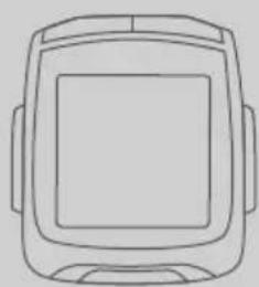
1 VDO computer
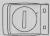
1 speed sensor
Battery installed
Accessories:

1 rubber pad
for speed sensor

1 battery 3 V-2032
for computer
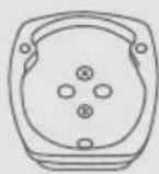
1 universal handlebar bracket
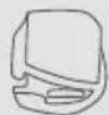
1 spoke magnet (clip magnet)
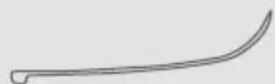
Cable ties for attaching the bracket and the transmitter
ENG
-
Display 42
-
Operation 44
-
Functions 46
3.1 Information functions, BIKE 46
3.2 Information functions, ALTI 47
3.3 PULSE option 48
3.4 CADENCE option 49
3.5 Information functions PULSE 49
3.6 Information functions CADENCE 50
3.7 Selection of BIKE 1 or BIKE 2 51
3.8 Pairing of transmitters, selecting the transmitters 52
3.9 Display backlight 53
3.10 Selecting an HR training zone 53
3.11 Selecting the start altitude / recalibrating the current altitude 54
3.12 Auto-starting/stopping the computer 55
3.13 Starting/stopping the stopwatch 55
- Reset
4.1 Resetting the trip data 56
4.2 Resetting the stopwatch 56
4.3 Resetting the NAVIGATOR 56
4.4. Resetting to factory settings 5
- Installation
5.1 Fitting the transmitter, magnet and handlebar bracket 57
5.2 Installing the battery in the computer 58
5.3 Inserting the computer into the handlebar bracket 58
- Basic settings 59
6.1. Selecting the language 59
6.2 Setting the units (kmh/mph, Meter/feet, Celsius/Fahrenheit, KG/LBS) 59
6.3 Setting the tyre size 60
6.4 Setting personal data 62
6.5 Selecting the transmitter (PULSE or CADENCE or NONE) 63
6.6.Setting the clock 64
6.7.Setting the odometer 65
6.8.Setting the navigator 66
6.9.Setting the ride time 67
6.10 Setting the start altitude/home altitude 68
6.11 Setting the current altitude/actual altitude 69
6.12 Automatic altitude adjustment during bike transport 70
6.13 Setting the altitude gain uphill 70
6.14 Setting the altitude loss downhill 71
6.15 Setting the beeper 72
- Sleep mode 73
- Terms of guarantee 74
- Troubleshooting 75
- Technical specifications 77
P02 references at the start of a section refer to the pictures in the picture book!
DE
FRETINPL

Your VDO computer comes without battery built in. Before you start, please insert battery. See also section 5.2.
1. Display
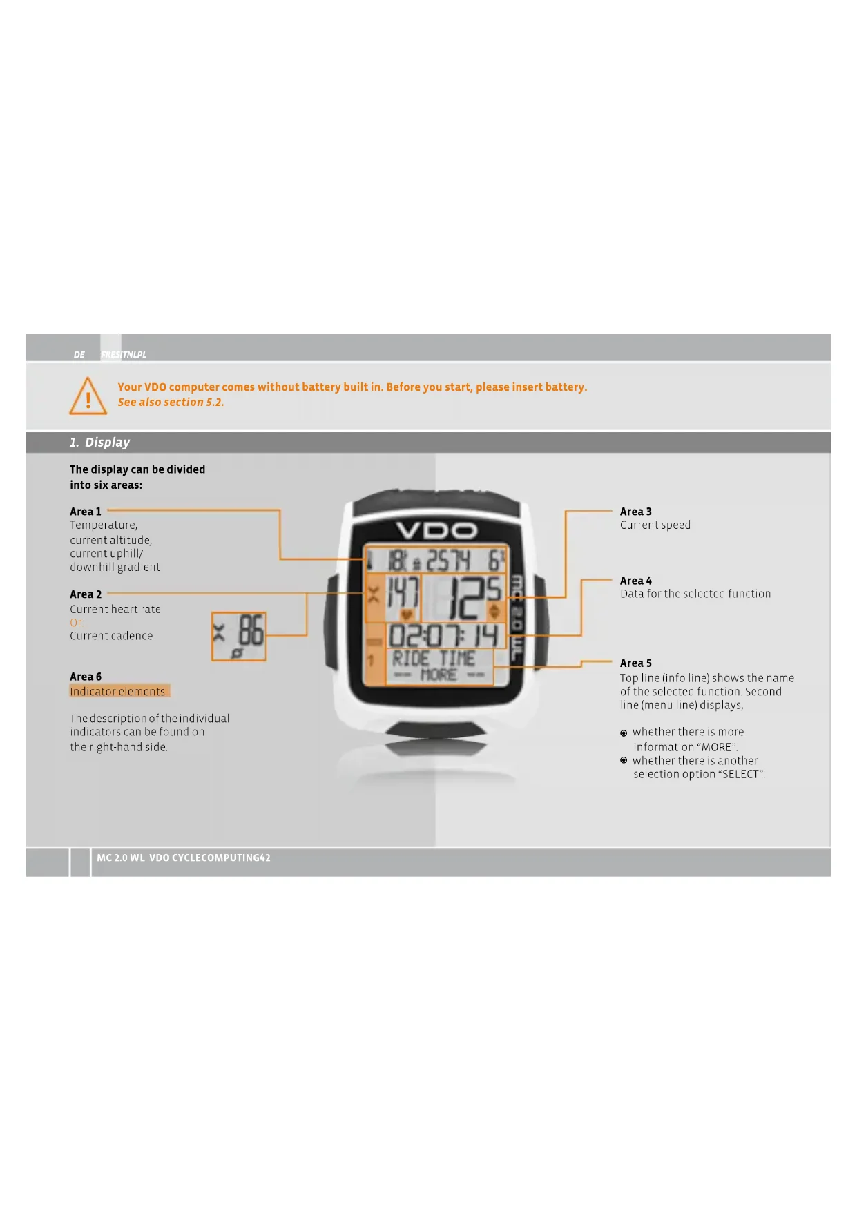
The display can be divided into six areas:
Area 1
Temperature,
current altitude,
current uphill/
downhill gradient
Area 2
Current heart rate
Current cadence
Area 6
Indicator elements
The description of the individual indicators can be found on the right-hand side.
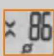
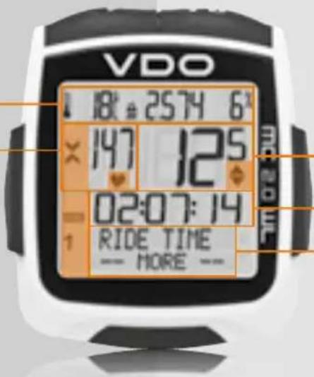
Area 3
Current speed
Area 4
Data for the selected function
Area 5
Top line (info line) shows the name of the selected function. Second line (menu line) displays,
whether there is more information "MORE".
whether there is another selection option "SELECT".

Stopwatch indicator
Shows that the stopwatch is still running whilst other information is provided on the display.

Indicator bike 1/bike 2
The computer can use two different settings for two bikes. The indicator shows which of the two bikes you have chosen to use. The total distance is measured and stored separately for bike 1 and bike 2.

Measurement unit (KMH or MPH)
The computer can display both KMH and MPH. Distances are correspondingly displayed in kilometers or miles. The indicator shows the selected measurement unit

Difference indicator - speed (current) to speed (average)
The computer compares the current speed with the average speed. The indicator shows whether the current speed is
- greater than the average speed (+1km / h)
less than the average speed (-1km / h)
or the same as the average speed (tolerance +/-1 km/h)

Menu prompt indicator
When a submenu has been accessed, these indicators flash and show that there are other selection options or that the computer is waiting for an entry (setting mode).

Display backlight
The LIGHT ICON indicates if the backlight-mode has been switched on.

Heart rate/cadence indicator
The indicator shows whether you have chosen the heartrate or the cadence sensor.

Zone indicator
The zone indicator shows whether your heart rate or cadence are within the set training zone.
Uparrow heart rate/cadence below the lower limit
- Down arrow: heart rate/cadence above the set upper limit
Both arrows: heart rate/cadence within the set training zone
2. Operation
To make your computer easy to use, we have developed the EMC = Easy Menu Control system. The EMC makes your computer easier to operate by means of full-text menu guidance, as is used on most mobile phones.
C = CLEAR
In function mode:
- Jump back a menu level from the submenu.
Press and hold for three seconds:
Reset trip data to zero.
Reset stopwatch to zero.
Reset navigator to zero.
In setting mode:
Press and hold for three seconds:
Exit the settings menu, return to function mode
Correct an entry.
- Jump back a digit
A = ALTI
In function mode:
In setting mode:
Altitude information is displayed.
Scroll backwards in the menu.
Decrease the number to be set.
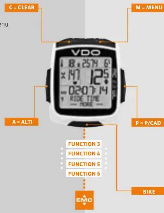
Menu indicators on the display flash to show that there are other selection options. In function mode, the computer is operated using five buttons. In setting mode, the computer is operated using four buttons.
M=MENU
In function mode:
Access available submenu
You can recognise a submenu by the flashing menu indicators.
Confirm selection.
Start/stop the stopwatch.
Press and hold for three seconds.
Open the settings menu.
In setting mode:
Select a setting
Confirm a setting
- Confirm a selection made
P-P/CAD
In function mode:
Heart rate information
or
Cadence information
In setting mode:
- Scroll forwards in the menu
Increase the number to be set.
BIKE = BIKE
In function mode:
Bike functions
ITNLPLFRES
IGDE
A = ALTI
In function mode:
Altitude information is displayed.
If the submenu is open:
Scroll down in the menu.
Press and hold ALTI for three seconds.
Opens the menu for recalibrating the current altitude.
In setting mode:
Scroll down within the setting modes.
Decrease a digit.
P = P/CAD
In function mode:
- Displays the heart rate information and the stopwatch (if heart rate has been paired).
Or:
Displays the cadence information and the stopwatch (if cadence has been paired).
- If the submenu is open: Scroll up in the submenu.
- Press and hold HR/CAD for three seconds: Opens the menu for selecting the heart rate training zone (if heart rate transmitter has been paired).
In setting mode:
- Scroll up within the setting modes.
- Increase a digit.
BIKE BIKE
- Displays the bike functions, e.g. trip distance, average speed etc.
BIKE + M = BIKE+MENU
Press the buttons BIKE+MENU (hold for three seconds) to open the menu for selecting the transmitter for heart rate or cadence.
A + P = ALTI + P
Press the buttons ALTI+P to start/stop the stopwatch.
The stopwatch immediately appears on the display and is started or stopped.
BIKE+ C = BIKE+CLEAR
Press the buttons BIKE+CLEAR to activate the display backlight.
- When the display backlight is activated, the LIGHT icon is displayed.
- When the display backlight is activated, the display is lit for a few seconds every time a button is pressed.
ATTENTION: press the buttons BIKE + CLEAR again to switch off the display backlight during the day.
This SAVES BATTERY POWER.
DE FRESITNLPL
3. Functions
3.1 Information functions, BIKE
CURRENT SPeeD
Permanently shown on the display. Accuracy:0,5 KMH/MPH
TRIP DISTANCE
Shows the distance of the current trip since the last reset. Maximum value 999.99 km. If the maximum value is exceeded, the odometer starts again at zero.
TRIP DISTANCE/MORE
MORE indicates that there is a submenu for the main menu TRIP DISTANCE. Open the submenu by pressing M.
In the submenu you will find (scroll by pressing ALTIA or P)
Total distance BIKE 1 up to max. 99,999 km
Total distance BIKE 2 up to max.99,999 km
Total distance for bike 1 + bike 2 up to max. 199,999 km Exit the submenu by pressing C.
RIDE TIME
Shows the ride time for the current trip distance since the last reset. Maximum 99:59:59 HH:MM:SS.
If the maximum value is exceeded, the ride time measurement starts again at zero.
RIDE TIME/MORE
MORE indicates that there is a submenu for the main menu RIDE TIME. Open the submenu by pressing M
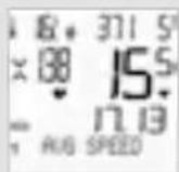
AVG SPeeD
Shows the average speed since the last reset. Accuracy: 2 decimal places.
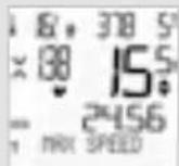
MAX SPeeD
Shows the maximum speed on the current trip since the last reset. Accuracy: 2 decimal places.
ITNLPLFRES
GOT
NAVIGATOR
The navigator is a second trip distance counter. The NAVIGATOR:
is independent of the trip distance counter.
can bereset to zero as often as you want.
can be set to a starting value.
can count forwards or backwards from this starting value. These special options make it easier to follow instructions from a touring book or road book.
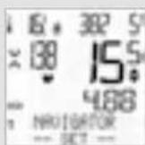
NAVIGATOR/SET
SET indicates that there is a submenu for the main menu NAVIGATOR. Open the submenu by pressing M
You can set a start value here and decide whether the NAVIGATOR counts forwards or backwards from this start value.
3.2 Information functions, ALTI
ALTIUP
Shows the altitude gain uphill on the current trip since the last reset.
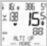
ALTI UP--MORE--
MORE indicates that there is a submenu for the main menu ALTI UP. Open the submenu by pressing M
In the submenu, you will find (scroll by pressing ALTIA or P)
Altitude gain uphill for bike 1
Altitude gain uphill for bike 2
Total altitude gain uphill for bikes 1 + 2
Exit the submenu by pressing
ALTIMAX
Shows the maximum altitude (highest point) reached on the current trip.
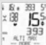
ALTIMAX--MORE--
MORE indicates that there is a submenu for the main menu ALTI MAX. Open the submenu by pressing
In the submenu, you will find (scroll by pressing ALTIA or P):
ALTI MAX for BIKE 1:
highest point of all previous trips with bike 1
ALTI MAX for BIKE 2:
highest point of all previous trips with bike 2.
DE FRESTNPLP
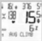
AVG CLIMB: average uphill gradient (in percent) on the current trip.
MAX CLIMB: maximum uphill gradient (in percent) on the current trip.
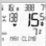
ALTI DOWN
Shows the altitude loss downhill on the current trip since the last reset.
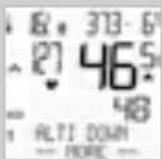
ALTIDOWN--MORE
MORE indicates that there is a submenu for the main menu ALTIDOWN. Open the submubny by pressing M
In the submenu, you will find (scroll by pressing ALTIP or PULSEP)
Altitude loss downhill for bike 1
Altitude loss downhill for bike 2
Total altitude loss downhill for bikes 1 + 2
Exit the submenu by pressing C
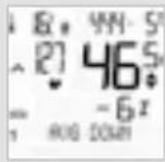
AVG DOWN: shows the average downhill gradient of the current trip (in percent).
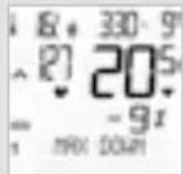
MAX DOWN: shows the maximum downhill gradient of the current trip (in percent).
3.3 PULSE option
P04-05
Selecting the pulse or cadence option
The PULSE menu is only available if:
the PULSE transmitter has been selected (see transmitter selection in sections 3.8 and 6.5)
the PULSE transmitter was paired during pairing.
Note: the heart rate and cadence cannot be received simultaneously.
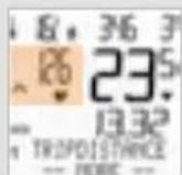
After pairing the PULSE transmitter, the current heartrate is shown in area 2 of the current HR display. In function mode, the functions can be accessed by pressing the button P/CAD p. RESETTING the trip data also resets the HR data to zero.
MC2.0 WL VDO CYCLECOMPUTING48
3.4 Cadence option >> P06
The cadence menu is only available if
the cadence transmitter has been installed.
the cadence transmitter has been selected (see transmitter selection in sections 3.8 and 6.5).
the transmitter was paired during pairing.
Note: the heart rate and cadence cannot be received simultaneously.
ITNPLFRES
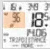
After pairing the cadence transmitter, the current cadence is shown in area 2 of the display. In function mode, the cadence information can be accessed by pressing the button P/CAD
Resetting the trip data also resets the cadence data to zero.
3.5 Information functions, PULSE
This information is only available if the PULSE transmitter has been selected and paired.
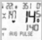
AVG PULSE: shows the average heart rate for the current trip (since the last reset).
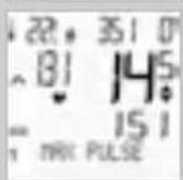
MAX PULSE: shows the maximum (highest) heart rate for the current trip (since the last reset).
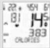
CALORIES: shows the calories burnt on the current trip (since the last reset).
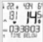
TIME BELOW: shows the time during which the heart rate was below the lower limit set for the training zone.
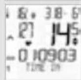
TIME IN: shows the time during which the heart rate was within the set training zone.
DE FRESTNPLP
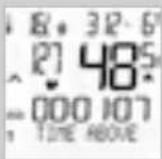
TIME ABOVE: shows the time during which the heart rate was above the upper limit set for the training zone.
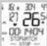
STOPWATCH: independent stopwatch for measuring times/intervals.
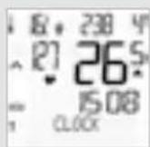
CLOCK: shows the current time.
12 hour AM/PM or 24 hour-mode possible.
3.6 Information functions, CADENCE
This information is available if the cadence transmitter has been selected and paired.
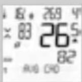
AVG CAD: shows the average cadence of the current trip (since the last reset).
MAX CAD: shows the maximum cadence of the current trip (since the last reset).
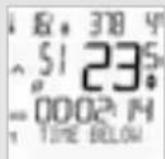
TIME BELOW: shows the time during which the cadence was below the lower limit set for the training zone.
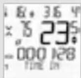
TIME IN: shows the time during which the cadence was within the set training zone.
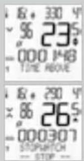
TIME ABOVE: shows the time during which the cadence was above the upper limit set for the training zone.
STOPWATCH: independent stopwatch for measuring times/intervals.
3.7 Selection of BIKE 1 or BIKE 2
P02
Your VDO computer can be used on two bikes. If you want to change from bike 1 to bike 2, the computer detects the transmitter for bike 2. The computer then automatically switches to bike 2. All data is now saved for bike 2. If you return to using the computer on bike 1, transmitter 1 is detected. The computer automatically switches to bike 1. The data is now saved for bike 1.
ITNPLFRES
GDE

CLOCK: shows the current time.
12 hour AM/PM or 24 hour-mode possible.
The selected bike 1 or 2 is shown at the bottom left of the display ( ).
Note: the transmitter on bike 2 must have been set to bike 2 before using it the first time.
P02
DE FRESTNPLP
3.8 Pairing of transmitters, selecting the transmitters
The speed, heart rate and cadence signals are transmitted to your computer in digital, encoded format. This technology is less prone to interference than analogue transmission, thus preventing data overlaps (cross talk) when cycling in a group. For the computer to acquire the digital encodings from the transmitter, pairing must occur:
Step 1 Select whether you want to view the heart rate or cadence or no heart rate/cadence data on the display.
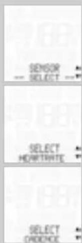
Press and hold M + for three seconds. Press ALTI A or P to select the desired transmitter CADENCE or HEARTRATE or NONE (no heart rate and no cadence). Confirm your selection by pressing M.
HEARTRATE--SELECT OK? or CADENCE--SELECT OK? or NONE--SELECT OK? appears on the display. Confirm the selection by pressing M. The MC 2.0 confirms by displaying SENSOR SELECT-DONE.
Step 2 Place the computer into the handlebar bracket. The speed and HR or cadence displays now flash. If you have not selected a transmitter (heart rate or cadence), only the speed display flashes. The flashing indicates that the computer is searching for its transmitter.
Step 3 Now spin the front wheel or simply set off and the computer acquires the digital encodings (pairing). If the pairing process was successful, the speed and heart rate or cadence will appear on the display.
ATTENTION: the time window for pairing is five minutes. If you do not start cycling during these five minutes, no pairing takes place. The speed, heart rate or cadence will not be displayed. The pairing then has to be repeated:
- If the computer has gone into sleep mode, a new pairing process is started by pressing a button. Alternatively: Place the computer back into the handlebar bracket.
ITNLPLFRES
GDB
3.9 Display backlight
The MC 2.0 has a display backlight.
The display backlight is activated by pressing the buttons If the display backlight is activated, the LIGHT icon appears on the display.
If the display backlight is activated and a button is pressed, the backlight illuminates for a few seconds.
ATTENTION: press the buttons BIKE + CLEAR again to switch off the display backlight during the day. This SAVES BATTERY POWER.
3.10 Selecting a PULSE training zone
If the PULSE transmitter has been selected, the P/CAD button can be used to select the training zone.
The MC 2.0 has three training zones.
Press and hold P/CAD for three seconds.
PULSE ZONE SELECT? flashes.
PULSE ZONE
FIT 134-153 (numerical example)
FAT 105-134 (numerical example)
OWN 105-155 (numerical example) is displayed.
The desired training zone is selected by pressing the P or ALTI button A The selection is confirmed by pressing the M button OWN 105-15S (numerical example) SELECT OK? Is queried. Confirmed by pressing the M button.
The MC 2.0 confirms by displaying PULSE ZONE-SELECT DONE.
For the FIT zone, the lower limit is calculated at 70 percent and the upper limit at 80 percent of the personal maximum heart rate.
For the FAT zone (fat-burning zone), the lower limit is calculated at 55 percent and the upper limit at 70 percent of the personal maximum heart rate.
The personal maximum heart rate is set in the settings under PERS. DATA (see section 6.4).
DE FRESTNPLP
3.11 Selecting the start altitude / recalibrating the actual altitude
The MC 2.0 can work with two different start altitudes (example: home altitude and altitude at holiday location). The current altitude can be set by entering the number of METERS or the AIR PRESSURE. Please also read section 6.10.
START ALTITUDE
Press and hold the ALTI button A for three seconds.
ALTITUDE SELECT? flashes on the display.
ALTITUDE
ACTUAL ALTI
HOME1
HOME2
is displayed (depending on the previously accessed configuration).
A selection is made by pressing ALTIA or P/CADP.
The selection is confirmed by pressing M
For the start altitudes, the query 300 appears (numerical example).
HOMEALT1(or2)SELECTOK
The selection is confirmed by pressing MENU.
The MC 2.0 confirms by displaying ALTITUDE DONE.
ACTUAL ALTITUDE
ACTUAL ALTITUDE can be used to re-calibrate the current altitude. This can be done by entering the (known) altitude in METERS or the AIR PRESSURE. The sea level pressure can be found online on weather forecast websites.
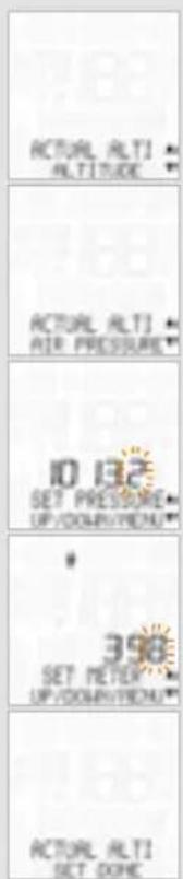
Press to confirm the ALTITUDE-ACTUAL ALTI setting. ACTUAL ALTI-ALTITUDE or ACTUAL ALTI-AIR PRESSURE is displayed.
A selection is made by pressing the P or ALTI button A. Confirm the selection by pressing M.
The digit to be set flashes.
Pressing P/CAD P or ALTI A increases or reduces the digit.
The following query then appears: ACTUAL ALTI-SELECT OK?
Confirm the selection by pressing M
The MC 2.0 confirms by displaying ACTUAL ALTI - SET DONE.
| ITNPLFRES GDE | |
| 3.12 Auto-starting/stopping the computer | |
| The MC 2.0 has a movement sensor. Following a break, the movement sensor automatically triggers the computer again when you start moving. | The computer can also be manually activated after a break by pressing a button. |
| 3.13 Starting/stopping the stopwatch | |
| To access the stopwatch directly, simultaneously press ALTIA + P. The stopwatch is shown directly on the display and started. | Pressing ALTIA + P again stops the stopwatch and displays it directly on the display. When shown on the display, the stopwatch can also be started/stopped by pressing the M button. |
| www.vdocyclecomputing.com MC 2.0 WL 55 | |
DE FRESTNPLP
4 Reset
4.1 Resetting the trip data
Press and hold the C button for three seconds to reset the trip data to zero before starting the next trip. TOUR-DATA-RESET? is shown on the display. If you continue to hold down the C button, the data will be reset.
The following values are reset:
Trip distance
Ride time
Average speed
Max speed
Gain in altitude uphill
Average ascending gradient
Max ascending gradient
Loss in altitude downhill
Average descending gradient
- Max descending gradient
If PULSE is selected:
Average heart rate
- Max heart rate
Calories
Time above
Time in
Time below
If CADENCE is selected:
Average cadence
Maxcadence
Time above
Time in
Time below
The query STOPWATCH\~RESET? appears on the display. The stopwatch is reset to zero.
4.2 Resetting the stopwatch
The stopwatch can only be reset when shown on the display.
To reset the stopwatch, press and hold the C button for three seconds.
The query NAVIGATOR-RESET? appears on the display. The navigator is reset to zero.
4.3 Resetting the NAVIGATOR
The navigator (2^nd trip section odometer) can only be reset when shown on the display.
To reset the navigator, press and hold the button for three seconds.
MC2.0 WL VDO CYCLECOMPUTING56
| ITNPLFRES GDE | |
| 4.4. Resetting to factory settings | |
| The MC 2.0 can be reset to the factory settings. ATTENTION: this process deletes all data and all personal settings. ● Press and hold all buttons simultaneously for three seconds. ● The query FACTORY-RESET appears on the display. RESET-SURE? | If you are absolutely sure that you want to reset the MC 2.0 to the factory settings, then confirm the query by pressing M. The MC 2.0 confirms by displaying RESET-DONE. |
| 5 Installation | |
| 5.1 Fitting the transmitter, magnet and handlebar bracket | >>> P01 |
| Start by fitting the transmitter and magnet. ATTENTION: the distance between the transmitter and the computer on the handlebars should not exceed 70 cm (transmission range). Step 1 Place the rubber pad under the transmitter. Fit the transmitter on the same side of the forks where you later want to fit the computer to the handlebars (right or left) using the cable ties supplied (loosely at first, do not pull tight just yet). ATTENTION: the sensor mark on the transmitter must point to the spokes. Depending on the room available, the sensor can be fitted at the front of the forks, on the inner side (side showing to spokes) of the forks or pointing backwards on the forks. >>> P03 | Step 2 Place the spoke magnet around an outer spoke. The silver centre of the magnet points towards the transmitter. Align the magnet to the sensor mark on the transmitter leaving a gap of about 1 - 5 mm. Step 3 Align the transmitter and magnet for good and fasten them in place: pull the cable ties tight and push the magnet in firmly. Step 4 Decide whether fitting to handlebars or stem and rotate the base of the handlebar holder by 90° accordingly. To do so, undo the screws in the bracket, take out the foot and rotate it 90°, insert and tighten the screws again. ATTENTION: do not overtighten the screws. |
| www.vdocyclecomputing.com MC 2.0 WL 57 | |
DE FRESITNLPL
Step 5 Guide the cable ties through the slot in the handlebar bracket, place around the handlebars or the stem and pull (do not pull tight just yet).
Step 6 If fitting to handlebars: align the computer angle to achieve optimum readability. Now pull the cable ties tight. Snip off protruding ends with clippers.
5.2 Installing the battery in the computer P07
Your VDO computer comes without battery built in. Before you start, please insert battery.
Step 1 Open the battery compartment lid with a coin.
Step 2 Place the battery in the computer casing with the +terminal pointing up.
Step 3 Make sure that the battery does not tilt.
Step 4 Ensure that the rubber seal lies flat on the battery compartment lid.
Step 5 Insert the battery compartment lid into the opening and use a coin to turn it to the right as far as it will go (approx. 1/3 turn).
Step 6 After inserting the battery, the computer will start the language select-mode. See chapter 6.1
TIP for changing batteries: VDO recommends changing the battery annually. Buy a new battery in good time to ensure the wireless transmission works perfectly. When the battery is changed, all settings and all trip totals are saved.
5.3 Inserting the computer into the handlebar bracket
The VDO twist-click system securely connects the computer to the handlebar bracket.
Step 1 Place the computer into the bracket in a 10 o'clock position.
Step 2 Twist the computer to the right until reaching the 12 o'clock position and click it into the bracket system.
>>>P08
Step 3 To remove the computer, twist it to the left (do not push or pull).
How to remember: Rigid to the Right, Loose to the Left
6. Basic settings
6.1 Setting the language
Press and hold M for three seconds.
When you set the language for the first time, the following appears:
SETTINGS--OPEN?, followed by LANGUAGE --SELECT... Confirm the selection by pressing M.
LANGUAGE-ENGLISH is shown on the display.
Press ALTi A or P to scroll until LANGUAGE --ENGLISH appears on the display. Confirm the selection by pressing M.
ENGLISH-SELECT-OK? appears in the display. Confirm the selection by pressing M
The MC 2.0 confirms by displaying SELECT-DONE--LANGUAGE. To exit settings mode, press and hold the c button for three seconds.
SETTINS-CLOSE? flashes. The MC 2.0 switches back to function mode.
6.2 Setting the dimensions
This area enables you to set the units for:
Speed and distance (KMH or MPH)
Altitude (meters or feet)
Temperature (Celsius or Fahrenheit)
Weight (kilos or pounds)
Process:
Press and hold M for three seconds. OPEN SETTING flashes. LANGUAGE---SELECT---appears on the display.
Press to scroll to DIMENSION--SET... Confirm the selection by pressing M.
DE FRESTNPLP
SPEED-KMH or MPH appears on the display. Press ALTI A or P to select KMH or MPH. Confirm the selection by pressing M.
ALTITUDE--METER or FEET is shown on the display. Press ALTI A or P to select METER or FEET. Confirm the selection by pressing M.
TEMPERATURE-CELSIUS or FAHRENHEIT is shown on the display. Press ALT A or P to select CELSIUS or FAHRENHEIT. Confirm the selection by pressing M.
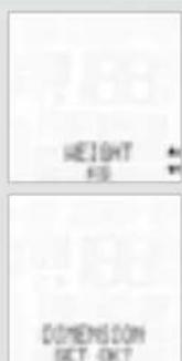
WEIGHT-KG or LBS is shown on the display. Press ALTIA or P to select KG or LBS. Confirm the selection by pressing M
Query, DIMENSION SET OK?
Press to confirm the DIMENSION or C to go back and change it.
The MC 2.0 confirms by displaying DIMENSION SET DONE.
To exit settings mode, press and hold the C button for three seconds. SETTINGS-CLOSE? flashes. The MC 2.0 switches back to function mode.
6.3 Setting the tyre size
This area is used to set the tyre circumference (tyre roll circumference). The tyre circumference can be separately set for bike 1 and bike 2. The tyre circumference can be manually entered in mm or automatically determined from a table with tyre sizes.
Process:
Press and hold for three seconds. SETTINGS-OPEN? flashes. LANGUAGE--SELECT--appears on the display.
Press to scroll to WHEEL SIZE---SET--- Confirm the selection by pressing M
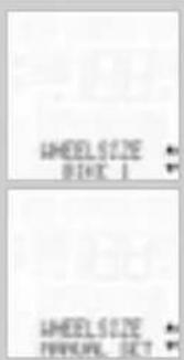
WHEEL SIZE-BIKE 1 or BIKE 2 is shown on the display.
Press ALTIA or P to select BIKE 1 or BIKE 2.
Confirm the selection by pressing M.
WHEEL SIZE--MANUAL SET or TYRE SELECT is shown on the display.
Press ALTIA or P to select MANUAL SET or TYRE SELECT list.
Confirm the selection by pressing M.
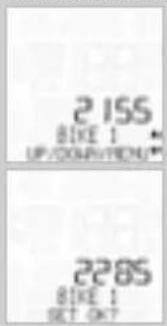
If MANUAL SET is selected:
The tyre size in mm flashes (if MPH is selected, the size is displayed in inches). Press ALTI A to reduce the tyre circumference or P to increase it.
Once you have set the correct tyre circumference, press M to confirm your setting.
BIKE 1 (or BIKE 2) SET OK? is shown on the display.
Press in confirmation or to make a correction.
The MC 2.0 confirms by displaying WHEEL SIZE-SET DONE.
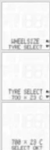
IF TYRE SELECT is selected:
Press ALTI A or P to scroll through the tyre list.
Once your tyre type is displayed (e.g. 700 x 23 C) confirm it by pressing M.
700 x 23 C-SELECT OK? is shown on the display. Press to confirm the selection or C to change it. The MC 2.0 confirms by displaying WHEEL SIZE-SET DONE.
To exit settings mode, press and hold the C button for three seconds. SETTINGS-CLOSE? flashes. The MC 2.0 switches back to function mode
An overview of the tyre list can be found in the picture book >> P07.
DE FRESTINPLP
6.4 Setting personal data
The personal data can be used to store details of your age, weight and gender. The MC 2.0 uses these details to calculate your personal maximum heart rate and thus the upper and lower limits for the heart rate training zones.
You can also specify the upper and lower limits for your own training zone in the personal settings.
Furthermore, you can specify the upper and lower limits for cadence training.
Process:
Press and hold for three seconds. OPEN SETTING flashes. LANGUAGE--SELECT--appears on the display.
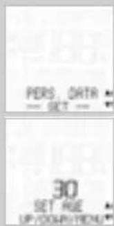
Press to scroll to PERS. DATA---SET--- Press Min confirmation.
SET AGE appears on the display. Press ALTI A to reduce the value or P to increase it.Once you have set the correct value, press M to confirm your setting.
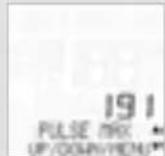

SET WEIGHT appears on the display. Press ALTI A to reduce the value or P to increase it.Once you have set the correct value, press M to confirm your setting.
SET SEX-MALE or FEMALE appears on the display. Press ALTi A or P to make a selection. Press Min confirmation.
PULSE MAX appears on the display. The maximum heart rate value calculated using the personal details flashes. Press ALTi A to reduce the value or P to increase it.Once you have set the correct value, press M to confirm your setting.
SET PULSE--LOW LIMIT appears on the display. Press ALTi A to reduce the value or P to increase it. Once you have set the correct value, press M to confirm your setting.
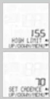
SET PULSE--HIGH LIMIT appears on the display Press ALTIA to reduce the value or P to increase it. Once you have set the correct value, press M to confirm your setting.
SET CADENCE-LOW LIMIT appears on the display. Press ALTiA to reduce the value or P to increase it.Once you have set the correct value, pressM to confirm your setting.
ITNPLFRES
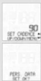
SET CADENCE-HIGH LIMIT appears on the display. Press ALTIA to reduce the value or P to increase it. Once you have set the correct value, press M to confirm your setting.
PERS. DATA-SET OK? query. Press in confirmation or to make a correction. The MC 2.0 confirms by displaying PERS. DATA-SET DONE.
To exit settings mode, press and hold the C button for three seconds. SETTINGS-CLOSE? flashes. The MC 2.0 switches back to function mode.
6.5 Selecting a sensor
See also section 3.8.
You can use this area to determine whether you want to ride with heart rate data or cadence data. You can change this before each trip.
Process:
Press and hold M for three seconds. SETTINGS-OPEN? flashes. LANGUAGE--SELECT--appears on the display.
Press to scroll to SENSOR--SELECT.. Press in confirmation.
DE FRESTNPLP
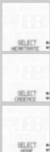
SELECT CADENCE or HEARTRATE or NONE appears on the display. Press ALTI A or P to make a selection. Press M in confirmation.
CADENCE or HEARTRATE or NONE--SELECT OK? is shown in display. Press in confirmation. The MC 2.0 confirms by displaying SENSOR--SELECT DONE.
To exit settings mode, press and hold the button for three seconds. SETTINGS-CLOSE? flashes. The MC 2.0 switches back to function mode.
6.6 Setting the clock
This area enables you to set the current time. The time can be set in 24 or 12-hour format.
Process: Press and hold for three seconds. SETTINGS-OPEN? flashes. LANGUAGE--SELECT--appears on the display.
Press to scroll to CLOCK-SET.. Press in confirmation.
CLOCK 24-H-MODE or 12-H-MODE appears on the display. Press ALTi A or P to make a selection. Press Min confirmation.
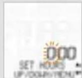
CLOCK---SET HOURS appears on the display. The hour flashes. Press ALTI A to reduce the value or P to increase it.Once you have set the correct value, press M to confirm your setting.
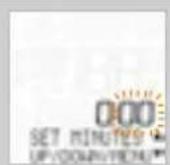
CLOCK---SET MINUTES appears on the display. Press ALTIA to reduce the value or P to increase it. Once you have set the correct value, press M to confirm your setting.
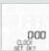
CLOCK--SET OK? query. Press in confirmation. The MC 2.0 confirms by displaying CLOCK--SET DONE.
To exit settings mode, press and hold the C button for three seconds. SETTINGS-CLOSE? flashes. The MC 2.0 switches back to function mode.
6.7.Setting the total distance
This area enables you to set the total distance cycled. The information is separately provided for bike 1 and bike 2. At the start of the season, you can reset the total distance cycled to zero, for example.
ATTENTION: the total distance is SAVED when the battery is changed. The data is not lost.
Process:
Press and hold M for three seconds. SETTINGS-OPEN? flashes. LANGUAGE--SELECT--appears on the display.
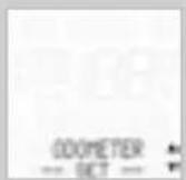
Press to scroll to ODOMETER---SET--- Press in confirmation.
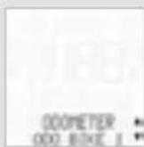
ODOMETER ODO BIKE 1 or ODO BIKE 2 is shown on the display. Press ALTIA or to make a selection. Press in confirmation.
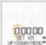
ODO BIKE 1 (or 2)-SET KM or SET MILE is shown on the display.
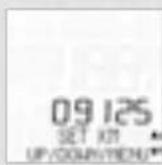
The first digit flashes. Press ALTiA to reduce the value or P to increase it.Once you have set the correct value, press M to confirm your setting.
The second digit now flashes.
Press ALTiA to reduce the value or to increase it.Once you have set the correct value, press M to confirm your setting. Continue the setting process until all digits have been set.
DE FRESTNPLP
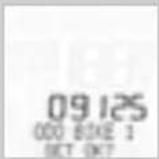
ODO BIKE 1 (or BIKE 2)--SET OK? Press M to confirm or C to make a correction.
The MC 2.0 confirms by displaying ODO BIKE 1 (or BIKE 2) SET DONE.
To exit settings mode, press and hold the button for three seconds. SETTINGS-CLOSE? flashes. The MC 2.0 switches back to function mode.
6.8 Setting the navigator
The navigator is directly set from the function menu
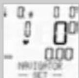
Process:
NAVIGATOR---SET--- is shown on the display. Press in confirmation.
NAVIGATOR--FORWARD or BACKWARD appears on the display.
Press ALTI A or P to make a selection.
Press in confirmation.
NAVIGATOR-SET DISTANCE appears on the display. The distance in meters flashes.
The first digit flashes.
Press ALTI A to reduce the value or P to increase it. Once you have set the correct value, press M to confirm your setting.
The second digit now flashes.
Press ALTI A to reduce the value or P to increase it. Once you have set the correct value, press M to confirm your setting.
Continue the setting process until all digits have been set.
NAVIGATOR--SET OK? query
Press in confirmation.
The MC 2.0 confirms by displaying NAVIGATOR-SET DONE. Once the setting is complete, the MC 2.0 automatically switches back to function mode.
6.9 Setting the ride time
The total ride time can be separately set for bike 1 and bike 2. Before the start of the season, you can reset the total ride time to zero.
ATTENTION: the total ride time is SAVED when the battery is changed. The data is not lost.
Process:
Press and hold M for three seconds. SETTINGS--OPEN? flashes. LANGUAGE--SELECT--appears on the display.
Press to scroll to RIDE TIME---SET--- Press in confirmation.
RIDE TIME-TIME BIKE 1 or TIME BIKE 2 is shown on the display. Press ALTIA or P to make a selection. Press M in confirmation.
TIME BIKE 1-SET HOURS appears on the display. The hours flash. Press ALTIA to reduce the value or P to increase it. Once you have set the correct value, press M to confirm your setting.
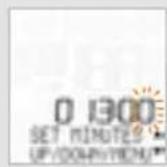
TIME BIKE 1--SET MINUTES appears on the display. The minutes flash.
Press ALTIA to reduce the value or P to increase it. Once you have set the correct value, press M to confirm your setting.
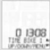
TIME BIKE 1-SET OK? Press in confirmation.
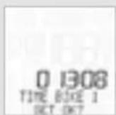
The MC 2.0 confirms by displaying TIME BIKE 1-SET DONE.
To exit settings mode, press and hold the C button for three seconds. SETTINGS-CLOSE? flashes. The MC 2.0 switches back to function mode.
DE FRESITNLPL
6.10 Setting the start altitude/home altitude
You can enter two different start altitudes in the MC 2.0. One start altitude can, for example, be your home start altitude. The second start altitude can, for example, be the start altitude of a holiday location. Before starting each trip, you can use the start altitude to quickly and easily re-calibrate the current air pressure in line with the start altitude set.
Topic: re-calibration
The MC 2.0 measures the altitude using the air pressure. The air pressure changes depending on the weather. The changed air pressure leads to an incorrect altitude reading. Through recalibration, the currently measured air pressure is calculated back to the set start altitude.
Process:
Press and hold for three seconds. SETTINGS-OPEN? flashes. LANGUAGE--SELECT--appears on the display.
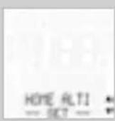
Press to scroll to HOME ALTI-SET.. Press in confirmation.
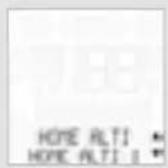
HOME ALTI-HOME ALTI 1 or HOME ALTI 2 appears on the display. Press ALTI A or P to make a selection. Press Min confirmation.
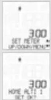
HOME ALTI 1-SET METER or SET FEET appears on the display. The meter or feet number flashes. Press ALTI A to reduce the value or P to increase it. Once you have set the correct value, press M to confirm your setting.
HOME ALTI 1-SET OK? Press in confirmation.
The MC 2.0 confirms by displaying HOME ALTI 1-SET DONE.
To exit settings mode, press and hold the button for three seconds. SETTINGS-CLOSE? flashes. The MC 2.0 switches back to function mode.
6.11 Setting the current altitude/actual altitude
This area enables you to set the current altitude.
The current altitude is set if the air pressure has changed due to the weather and the altitude shown on the display no longer corresponds to the actual current altitude (e.g. the altitude details shown at the summit).
There are two ways of setting the current altitude. Enter the current altitude in meters/feet or the sea level pressure. On entering the sea level pressure, the current altitude is calculated.
Details of the sea level pressure can be found at www.meteo24.de, for example.
Process:
Press and hold M for three seconds. SETTINGS-OPEN? flashes. LANGUAGE---SELECT--- appears on the display.
Press ALTIA to scroll to ACTUAL ALTI--- SET--- Press in confirmation.
ACTUAL ALTI-ALTITUDE or AIR PRESSURE appears on the display.
Press ALTI A or P to make a selection. Press in confirmation.
If ALTITUDE is selected:
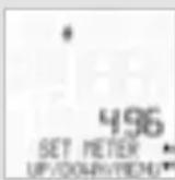
ACTUAL ALTI-SET METER or FEET appears on the display. The meter or feet number flashes. Press ALTI A to reduce the value or P to increase it. Once you have set the correct value, press M to confirm your setting.
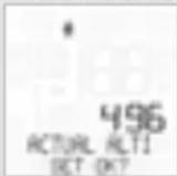
ACTUAL ALTI--SET OK? Press in confirmation.
The MC 2.0 confirms by displaying ACTUAL ALTI-SET DONE.
DE FRESTNPLP
If AIR PRESSURE is selected:
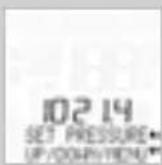
AIR PRESSURE-SET PRESSURE appears on the display. The air pressure number flashes Press ALTI A to reduce the value or P to increase it.Once you have set the correct value, press M to confirm your setting.
Dimension of Air Pressure is hPa.
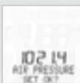
AIR PRESSURE-SET OK? Press in confirmation.
The MC 2.0 confirms by displaying ACTUAL ALTI-SET DONE.
To exit settings mode, press and hold the button for three seconds. CLOSE SETTING flashes. The MC 2.0 switches back to function mode.
6.12 Adjusting the altitude when transporting the bike
The MC 2.0 has a movement sensor. If the bike is transported with the MC 2.0 (e.g. by car), the movement sensor will adjust the current altitude if the air pressure changes during transportation.
To do this, the MC 2.0 WL must be positioned in the handlebar bracket.
6.13 Setting the altitude gain uphill
The altitude gain uphill can be separately set for BIKE 1 and BIKE 2.
Before the start of the season, you can reset the total altitude gain to zero.
ATTENTION: the total altitude gain is SAVED when the battery is changed. The data is not lost.
Process: Press and hold for three seconds. SETTINGS-OPEN? flashes. LANGUAGE--SELECT--appears on the display.
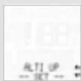
Press to scroll to ALTI UP-SET Press Min confirmation.
MC 2.0 WL VDO CYCLECOMPUTING70
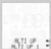
ALTIP-ALTIPU1 or 2 is shown on the display. Press ALTIA or P to make a selection. Press in confirmation.
ALTIPUSETMETERorFEETappears on the display.
The first digit of the altitude reading flashes..
Press ALTI A to reduce the value or P to increase it.
Once you have set the correct value, press M to confirm your setting.
The second digit flashes. Press ALTI A to reduce the value or P to increase it. Once you have set the correct value, press M to confirm your setting. Continue the setting process until all digits have been set.
ITNLPLFRES
G
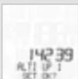
ALTI UP 1-SET OK? Press in confirmation.
The MC 2.0 confirms by displaying ALTI UP 1--SET DONE.
To exit settings mode, press and hold the C button for three seconds.
SETTINGS-CLOSE? flashes. The MC 2.0 switches back to function mode.
6.14 Setting the altitude loss downhill
The altitude loss downhill can be separately set for bike 1 and bike 2. Before the start of the season, you can reset the total altitude loss to zero.
ATTENTION: the total altitude loss is SAVED when the battery is changed. The data is not lost.
Process: Press and hold for three seconds. SETTINGS-OPEN? flashes. LANGUAGE--SELECT appears on the display.
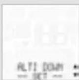
Press to scroll to ALTI DOWN-SET Press in confirmation.
DE FRESTNPLP
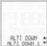
ALTI DOWN-ALTI DOWN 1 or 2 is shown on the display.
Press ALTI A or P to make a selection.
Press in confirmation.
ALTI DOWN 1--SET METER or FEET appears on the display.
The first digit of the altitude reading flashes.
Press ALTIA to reduce the value or P to increase it.
Once you have set the correct value, press to confirm your setting.
The second digit flashes.
Press ALTI A to reduce the value or P to increase it
Once you have set the correct value, press to confirm your setting.
Continue the setting process until all digits have been set.
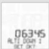
ALTIDOWN1-SETOK?
Press M in confirmation.
The MC 2.0 confirms by displaying ALTI DOWN 1-SET DONE.
To exit settings mode, press and hold the C button for three seconds. SETTINGS-CLOSE? flashes. The MC 2.0 switches back to function mode.
6.15 Setting the beeper
This area enables you to switch the heart rate warning beeper on or off. If the current heart rate is below the lower limit set or above the upper limit set, the beeper will beep.
Process:
Press and hold M for three seconds. SETTINGS--OPEN? flashes.
LANGUAGE--SELECT--appears on the display.
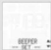
Press ALTI A or P to scroll to BEEPER---SET---
Press in confirmation.
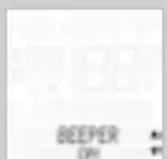
BEEPER-ON or OFF appears on the display.
Press ALTIA or P to make a selection.
Press in confirmation.
BEEPER ON (or OFF)--SET OK? Press in
confirmation.
The MC 2.0 confirms by displaying BEEPER-SET DONE.
ITNLPLFRES
GDE
To exit settings mode, press and hold the C button for three seconds. SETTINGS-CLOSE? flashes. The MC 2.0 switches back to function mode.
7. Sleep mode
The MC 2.0 has a sleep mode to save the battery.
The MC 2.0 goes into sleep mode after five minutes
if no speed signals are received. SLEEP MODE
PRESS BUTTON appears on the display.
Pressing any button or moving the handlebars reactivates/wakes up
the MC 2.0
DE FRESITNLPL
8. Terms of guarantee
VDO Cycle Parts offers a 3-year guarantee on your VDO computer, starting from date of purchase. This guarantee covers material and processing defects on the computer itself, the sensor/transmitter and the handlebar bracket. Cables, batteries and mounting materials are not covered by the guarantee. The guarantee is only valid if the affected components have not been opened (exception: computer's battery compartment), no force has been used and there is no sign of wilful damage.
Please store the purchase receipt in a safe place as it must be submitted in the event of a complaint.
If your complaint is legitimate, you will receive a comparable replacement device. You are not entitled to a replacement of the identical model if the model in question is no longer in production due to a model change. Please contact the dealer from whom you purchased the device for all complaints and guarantee claims. Alternatively, send your complaint directly to:
Cycle Parts GmbH
Le Quartier Hornbach 13
67433 Neustadt/Weinstrasse (Germany)
If you have any technical questions, please do not hesitate to call our hotline during standard office hours on:
+49(0)6321-95827-10
+49(0)6321-95827-18
Additional technical information is available at: www.vdocyclecomputing.com
We reserve the right to make technical changes in the course of further development.
9. Troubleshooting
Error Possible cause Correction
| Half segments on the display (e.g. after a battery change) | Computer software not running correctly after battery change | Take out the battery, wait a few seconds, place battery back again |
| No speed displayed Distance from sensor to magnet too great Correct the sensor and magnet positions | ||
| No speed displayed Computer not properly clicked into the handlebar bracket | Place the computer head in the handlebar bracket and twist it until it clicks | |
| No speed displayed Wheel circumference is not correctly set or is at zero | Set the wheel circumference | |
| No speed displayed Battery in the transmitter is dead Replace the battery in the transmitter | ||
| No speed displayed | Speed transmitter has not been paired | Insert the computer into the handlebar bracket, speed indicator flashes, now turn the front wheel, transmitter is paired, speed is displayed |
| Speed doubled | Magnet is incorrectly positioned | Correct the position of the magnet on the spoke |
| Display becomes weak | Battery dead | Check the battery, replace if nec. |
| Display becomes weak | Temperatures under 5° make the display sluggish | At normal temperatures the display will work normally again |
| Incorrect altitude displayed (current altitude incorrect) | Air pressure has changed but the current altitude has not been recalibrated in line with the new air pressure | Recalibrate the current altitude |
Error Possible cause Correction
| No heart rate displayed | Heart rate sensor has not been selected. | Select the heart rate sensor from the sensor selection area |
| No heart rate displayed | Heart rate sensor has not been paired | Select the heart rate sensor, correctly position the heart rate chest belt on your body. Insert the computer into the handle-bar bracket, heart rate symbol flashes to indicate pairing |
| No heart rate displayed | Battery in the heart rate chest belt is dead | Replace the battery in the heart rate chest belt |
| No cadence displayed | Cadence sensor has not been selected. | Select the cadence sensor from the sensor selection area |
| No cadence displayed | Cadence sensor has not been paired | Select the cadence sensor. Insert the computer into the handlebar bracket, cadence symbol flashes to indicate pairing |
| No cadence displayed | Battery in the cadence chest belt is dead | Replace the battery in the cadence chest belt |
| No cadence displayed | Magnet incorrectly positioned | Correct the magnet position |
| No cadence displayed | Magnet positioned too far from the transmitter | Move the magnet or the transmitter to reduce the distance |
| Cadence display doubled | Magnet incorrectly positioned | Correct the magnet position |
10. Technical specifications
Computer:
Approx. 54 H x 49 W x 15 D mm, weight: approx. 45 g
Handlebar bracket:
Weight: approx. 10 g
Speed/cadence transmitter:
Weight approx. 20g
Heart rate transmitter:
Weight: approx. 50 g
Computer battery:
3V, type 2032
Computer battery service life:
400 ride hours,approx.8,000 km (5000 m)
Speed transmitter battery:
3v,type 2032
Speed transmitter battery service life:
1000 ride hours, approx. 20,000 km (12,000 m)
Cadence transmitter battery service life:
1000 ride hours,approx.20,000 km (12,000 m)
Heart rate transmitter battery service life:
1000 ride hours, approx. 20,000 km (12,000 m)
Display operating temperature:
-10°C to +60°C (14°F to 140°F)
Speed range:
For wheel size 2155 mm,
min 2.0km / h
max 116 km/h
Ridetime measurement range:
Up to 99:59:59 HH:MM:SS.
Stopwatch measurement range:
Up to 99:59:59 HH:MM:SS.
Trip distance odometer measurement range:
Up to value 999.99 km or mi
NAVIGATOR measurement range:
from -999.99 to +999.99 km or mi
Total distance 1 or total distance 2 measurement range:
Up to value 99,999 km or mi
Total distance ODO 1 + ODO 2 measurement range:
Up to value 199,999 km or mi
Heart rate measurement range:
40 to 240 bpm
Cadence measurement range:
20 to 180 rpm
Altitude measurement range:
-999 m to +4999 m (-999 to 16 400 feet)
Wheel circumference setting ra
From 100 mm to 3999 mm (3.9 to 157.4 inches)
DEENG
ESITNLPL
Preface
Merci!
P = Pulse (FC) / CAD
BIKE + C = BICI+CLEAR
Meeteenheid (KMH of MPH)
ENG Correct Disposal of This Product (Waste Electrical & Electronic Equipment)
(Applicable in the European Union and other European countries with separate collection systems). This marking shown on the product or its literature, indicates that it should not be disposed with other household wastes at the end of its working life. To prevent possible harm to the environment or human health from uncontrolled waste disposal, please separate this from other types of wastes and recycle it responsibly to promote the sustain-able reuse of material resources. Household users should contact either the retailer where they purchased this product, or their local government office, for details of where and how they can take this item for environmentally safe recycling. Business users should contact their supplier and check the terms and conditions of the
purchase contract. This product should not be mixed with other commercial wastes for disposal.

EU-Declaration of Conformity
We, CYCLE PARTS GmbH, Le Quartier Hornbach 13, D-67433 Neustadt/Weinstr. declare under our responsibility that the product VDO MC 2.0 WL and all transmitters SPD-TX, CAD-TX and PULS-TX are compliant with the essential requirements and other relevant requirements of the R&TTE Directive 1999/5/EG. The declaration of Conformity can be found at www.vdocyclecomputing.com.
FR
NOTICE: This equipment has been tested and found to comply with the limits for a Class B digital device, pursuant to Part 15 of the FCC Rules. These limits are designed to provide reasonable protection against harmful
interference in a residential installation. This equipment generates, uses and can radiate radio frequency energy and, if not installed and used in accordance with the instructions, may cause harmful interference to radio communications. However, there is no guarantee that interference will not occur in a particular installation. If this equipment does cause harmful interference to radio or television reception, which can be determined by turning the equipment off and on, the user is encouraged to try to correct the interference by one or more of the following measures:
Reorient or relocate the cycle computer head with the receiving antenna.
- Increase the separation between your equipment and the cycle computer head with the receiving antenna.
- Consult your bicycle dealer or an experienced radio/TV technician for help.
NOTICE: This device complies with Part 15 of the FCC Rules.
Operation is subject to the following two conditions: (1) this device may not cause harmful interference, and (2) this device must accept any interference received, including interference that may cause undesired operation.
NOTICE: Warning: Changes or modifications made to this equipment not expressly approved by VDO Cycle Parts GmbH may void the FCC authorization to operate this equipment.
IC-Addendum
IC ID 5957A7704
Heart-rate transmitter CP7704
IC ID 5957A7705
Cadence transmitter CP7705
IC ID 5957A7706
Speed Transmitter CP7706
IC statement
This Class B digital apparatus complies with Canadian ICES 003.
Cet appeareil numerique de la classe B est conforme a la norme NMB 003 du Canada.
This device complies with Industry Canadian licence-exempt RSS standard(s).
Operation is subject to the following two conditions:
(1) this device may not cause interference, and
(2) this device must accept any interference, including interference than may cause undesired operation of the device.

- Pack contents
- ENG
- Display
- The display can be divided into six areas:
- Area 1
- Area 2
- Area 6
- Indicator elements
- Area 3
- Area 4
- Area 5
- Stopwatch indicator
- Indicator bike 1/bike 2
- Measurement unit (KMH or MPH)
- Difference indicator - speed (current) to speed (average)
- Menu prompt indicator
- Display backlight
- Heart rate/cadence indicator
- Zone indicator
- Operation
- C = CLEAR
- In function mode:
- In setting mode:
- A = ALTI
- M=MENU
- P-P/CAD
- BIKE = BIKE
- P = P/CAD
- BIKE BIKE
- BIKE + M = BIKE+MENU
- A + P = ALTI + P
- BIKE+ C = BIKE+CLEAR
- Functions
- Information functions, BIKE
- CURRENT SPeeD
- TRIP DISTANCE
- TRIP DISTANCE/MORE
- RIDE TIME
- RIDE TIME/MORE
- AVG SPeeD
- MAX SPeeD
- NAVIGATOR
- NAVIGATOR/SET
- Information functions, ALTI
- ALTIUP
- ALTI UP--MORE--
- ALTIMAX
- ALTIMAX--MORE--
- ALTI MAX for BIKE 1:
- ALTI MAX for BIKE 2:
- ALTI DOWN
- ALTIDOWN--MORE
- Selecting the pulse or cadence option
- Cadence option >> P06
- Information functions, PULSE
- This information is only available if the PULSE transmitter has been selected and paired.
- Information functions, CADENCE
- Selection of BIKE 1 or BIKE 2
- Pairing of transmitters, selecting the transmitters
- Display backlight
- Selecting a PULSE training zone
- Selecting the start altitude / recalibrating the actual altitude
- START ALTITUDE
- ACTUAL ALTITUDE
- Reset
- Resetting the trip data
- The following values are reset:
- If PULSE is selected:
- If CADENCE is selected:
- Resetting the stopwatch
- The stopwatch can only be reset when shown on the display.
- Resetting the NAVIGATOR
- The navigator (2nd trip section odometer) can only be reset when shown on the display.
- DE FRESITNLPL
- Installing the battery in the computer P07
- Inserting the computer into the handlebar bracket
- >>>P08
- Basic settings
- Setting the language
- Setting the dimensions
- Process:
- DE FRESTNPLP
- Setting the tyre size
- Setting personal data
- Selecting a sensor
- Setting the clock
- 6.7.Setting the total distance
- Setting the navigator
- Setting the ride time
- Setting the start altitude/home altitude
- Topic: re-calibration
- Setting the current altitude/actual altitude
- If ALTITUDE is selected:
- If AIR PRESSURE is selected:
- Adjusting the altitude when transporting the bike
- Setting the altitude gain uphill
- Setting the altitude loss downhill
- Setting the beeper
- Sleep mode
- Terms of guarantee
- Cycle Parts GmbH
- Troubleshooting
- Technical specifications
- Computer:
- Handlebar bracket:
- Speed/cadence transmitter:
- Heart rate transmitter:
- Computer battery:
- Computer battery service life:
- Speed transmitter battery:
- Speed transmitter battery service life:
- Cadence transmitter battery service life:
- Heart rate transmitter battery service life:
- Display operating temperature:
- Speed range:
- Preface
- P = Pulse (FC) / CAD
- BIKE + C = BICI+CLEAR
- Meeteenheid (KMH of MPH)
- ENG Correct Disposal of This Product (Waste Electrical & Electronic Equipment)
- EU-Declaration of Conformity
- FR
- IC-Addendum
- IC statement
Brand : VDO
Model : MC 2.0 WL
Category : Meter