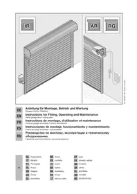
ProMatic P - Garage door Hormann - Free user manual and instructions
Find the device manual for free ProMatic P Hormann in PDF.
Frequently Asked Questions - ProMatic P Hormann
User questions about ProMatic P Hormann
0 question about this device. Answer the ones you know or ask your own.
Ask a new question about this device
Download the instructions for your Garage door in PDF format for free! Find your manual ProMatic P - Hormann and take your electronic device back in hand. On this page are published all the documents necessary for the use of your device. ProMatic P by Hormann.
USER MANUAL ProMatic P Hormann
natural_image
Interior view of a car with a driver using a steering wheel, showing a curved light pattern and an inset photo of a device (no text or symbols visible)Installation, Operating and Maintenance Instructions
Garage Door Operator
text_image
A E FCBA D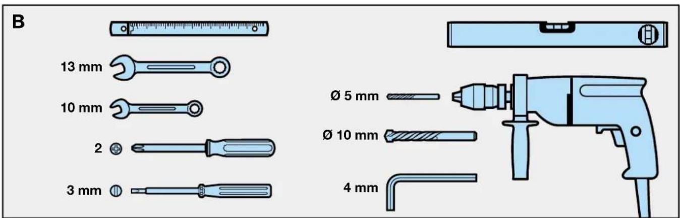
text_image
B 13 mm 10 mm 2 3 mm Ø 5 mm Ø 10 mm 4 mmtext_image
Safety warning illustration showing a person adjusting a door panel with warning symbols and warning signstext_image
Safety warning illustration showing a child sitting on the floor next to a door, with a warning symbol and exclamation mark.text_image
Safety warning illustration showing car accident with warning triangle and soccer ball symbol
ACHTUNG
B Required Tools for Installation 2
1 Important Notes 7
1.1 Important safety instructions 7
1.1.1 We shall be exempt from our warranty obligations and product liability in the event that ... 7
1.1.2 Checking the door / door system 7
1.2 Important instructions for safe installation 7
1.2.1 Prior to installation 7
1.2.2 In carrying out the installation work 7
1.3Warnings 8
1.4 Maintenance advice 8
1.5 Information on the illustrated section 8

Illustrated Section 18-30
2 Installation Instructions
2.1 Required clearance for installing the operator 38
2.2 Door latches on an up-and-over door 38
2.3 Door latches on a sectional door 38
2.4 Up-and-over doors with a forged iron door handle 38
2.5 Central locking on a sectional door 38
2.6 Off-centred reinforcement profile on a sectional door 38
2.7 Tensioning the drive belt 38
3 Putting into Service / Connecting Additional Components / Operation 38
3.1 Establishing the door's end-of-travel positions by installing the limit stops 38
3.2 Notes on work involving electrics 38
3.3 Putting the operator into service 38
3.3.1 Deleting the door data 38
3.3.2 Programming the operator 39
3.3.3 Setting the maximum forces 39
3.4 Other adjustment options 40
3.5 Connecting of the additional components 40
3.5.1 Connecting the remote control 40
3.5.2 Connecting external IMPULSE buttons to start or stop travel cycles 41
3.5.3 Connecting an OFF-switch or a wicket door contact to halt and / or switch off the operator 41
3.5.4 Connecting a photocell or closing edge safety device 41
3.5.5 Connecting to the options relay 41
3.6 Notes on operating the garage door operator 41
3.6.1 Normal operation 42
3.6.2 Operation following actuation of the mechanical release 42
3.6.3 Signals from the operator lighting 42
3.6.4 Error messages / diagnostic LED 42
4 Terms and Conditions of the Warranty 43
5 Technical Data
38
Copyright.
No part of this instruction manual may be reproduced without our permission.
4 Subject to changes.
ENGLISH
Dear Customer,
Thank you for choosing a quality product from our company. Please keep these instructions safe for later reference!
Please observe the following instructions, they provide you with important information on the safe installation and use of your Garage Door Operator, thus ensuring that this product will give you trouble free operation for many years to come.
1 Important Notes

ATTENTION Incorrect installation or handling of the operator could result in serious injury. Please therefore follow these instructions fully and with extreme care!
1.1 Important safety instructions
This garage door operator is designed exclusively for the automated operation of spring-balanced up-and-over and sectional doors in the non-commercial sector. Use in the commercial sector is not permitted.
1.1.1 We shall be exempt from our warranty obligations and product liability in the event that the customer carries out his own structural changes or undertakes improper installation work or arranges for same to be carried out without our prior approval and contrary to the installation guidelines we have provided. Moreover, we shall accept no responsibility for the inadvertent or negligent operation of the operator and accessories nor for the improper maintenance of the door and its counterbalance mechanism. Batteries and light bulbs are also not covered by the warranty.
The design of the operator is not suitable nor intended for the opening and closing of heavy doors, i.e. doors that can no longer easily be opened or closed manually. Before installing the operator, it is therefore necessary to check the door and make sure that it can also be easily moved by hand.
To do this, raise the door approx. 1 metre and then let it go. The door should retain this position, moving neither up or down. If the door should move in any of the two directions, there is a risk that the compensating springs are defective or incorrectly adjusted. In this case increased wear and malfunctioning of the door system can be expected.

CAUTION: Danger to life!
Do not attempt to change, re-adjust, repair or move the compensating springs for the door's counterbalance mechanism or their holders. The springs are under great tension and can cause serious injury.
In addition, check the entire door system (pivots, door bearings, cables, springs and fastenings)
for wear and possible damage. Check for signs of rust, corrosion or fractures. The door system may not be used if repair or adjustment work needs to be carried out. Always remember that a fault in the door system or a misaligned door can also cause injury.
Note
Before installing the operator and in the interests of personal safety, make sure that any work needed on the door's compensating springs is carried out by your garage door's service engineers. This also applies to any necessary maintenance or repair work.
1.2 Important instructions for safe installation
Any further processing must ensure that the national regulations governing the operation of electrical equipment are complied with.
1.2.1 Before installing the garage door operator, check that the door is in a good mechanical condition and is correctly balanced. Further check whether the door opens and closes in the proper manner (see section 1.1.2). In addition, any of the door's mechanical locks and latches not needed for power operation of the garage door should be immobilised. This includes in particular any locking mechanisms connected with the door lock (see sections 2.2 to 2.3).
The garage door operator is designed for use in dry buildings and therefore may not be installed outdoors. The garage ceiling must be constructed in such a way as to guarantee safe, secure anchoring of the operator. In the case of ceilings that are too high or too lightweight, the operator must be attached to additional braces.
1.2.2 In carrying out the installation work the applicable regulations regarding working safety must be complied with.

ATTENTION
Always cover over the operator before drilling, since drilling dust and chippings can lead to malfunctions.
The clearance between the highest point of the door and the ceiling (also when the door is opening) must be at least 30 mm (see fig. 1.1a / 1.1b). If there is inadequate clearance, the operator may also be installed behind the opened door, provided sufficient space is available. In such instances an extended door link must be used. The garage door operator can be positioned off-centre by max. 50 cm, the exception being sectional doors with high-lift tracks (track application "H"), where a special track fitting is required.
The required shockproof electric socket allowing the operator to be connected to the electricity supply should be installed at a distance of approx. 50 cm from the operator head.
Please check these dimensions!
ENGLISH
Note
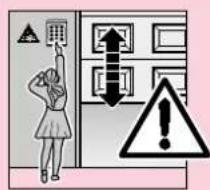
A caution notice warning about the trap risk must be permanently fixed in a conspicuous place close to the permanently installed buttons used to actuate the operator.
1.3 Warnings
text_image
Safety warning illustration showing a person pressing a grid with warning symbols and an explosion symbolPermanently installed controls (such as buttons or similar devices) should be installed within sight of the door but well away from any moving parts and at a height of at least 1.5 metres. It is vital that they are installed out of the reach of children!
text_image
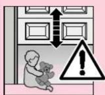
Safety warning illustration showing a baby teddy bear inside a room with upward arrows and a warning symbol.Make sure that
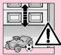
- neither persons nor objects are located within the door's range of travel.
- children do not play around with the door system!
- the cord of the mechanical release on the carriage cannot get caught up in the ceiling's support system or in any other protruding parts of vehicles or the door.
text_image
Safety warning illustration showing a car accident with warning symbols and an explosion symbol
ATTENTION
For garages without a second entrance, an emergency release must be fitted to ensure that is no danger of getting locked out.
This must be ordered separately and its function checked once a month.

ATTENTION
Do not allow anyone to hang bodily from the pull cord with knob!
1.4 Maintenance advice
The garage door operator is maintenance-free. For your own safety, however, we recommend that you have the door system checked once a year by service engineers qualified to inspect and service garage doors.
1.5 Information on the illustrated section
The illustrated section shows installation of the operator on an up-and-over door.
Where installation differs for a sectional door, this is shown in addition.
In this instance, letters are assigned to the figures as follows:
(a) is assigned to the up-and-over door and
b to the sectional door.
Some of the figures also include the symbol shown below together with a text reference. These references to specific texts in the ensuing text section provide you with important information regarding installation and operation of the garage door operator.
Example:

= see text section, point 2.2
TABLE DES MATIERES PAGE
A Articles livrés 2
text_image
Safety warning illustration showing a person adjusting a grid with warning symbols and an upward arrow indicating deterioration.text_image
Safety warning illustration showing a person pressing a grid with warning symbols and an explosion symboltext_image
Safety warning illustration showing a child holding a teddy bear, with warning symbols and an upward arrow indicating improvement.text_image
Safety warning illustration showing a car accident with a warning triangle and warning symbol
LET OP:
text_image
Safety warning illustration showing a person pressing a grid with warning symbols and a warning triangle.text_image
Safety warning illustration showing a child holding a teddy bear next to a door with an upward arrow and warning symbolAccertare che
text_image
Safety warning illustration showing a car accident with warning symbol and building structure
ATTENZIONE!
text_image
Technical diagram showing a warning sign with a red X mark and a warning triangle symbol, likely indicating a hazard or hazard.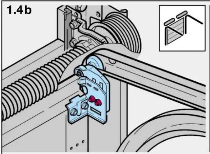
text_image
1.4b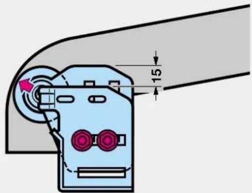
text_image
15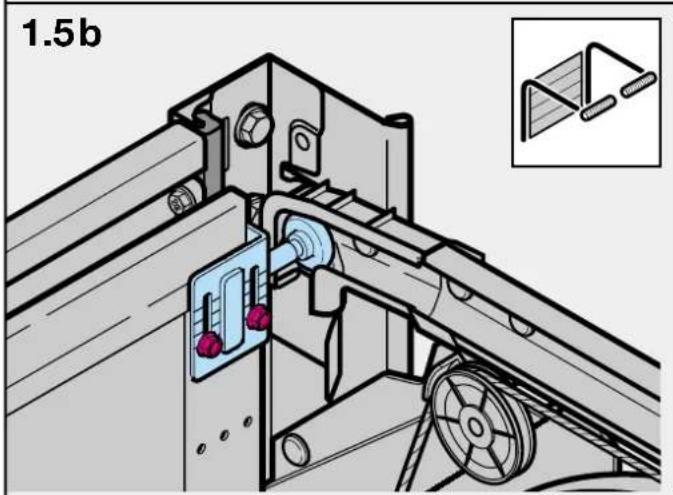
natural_image
Technical diagram of a mechanical assembly with pulleys and components, no visible text or symbols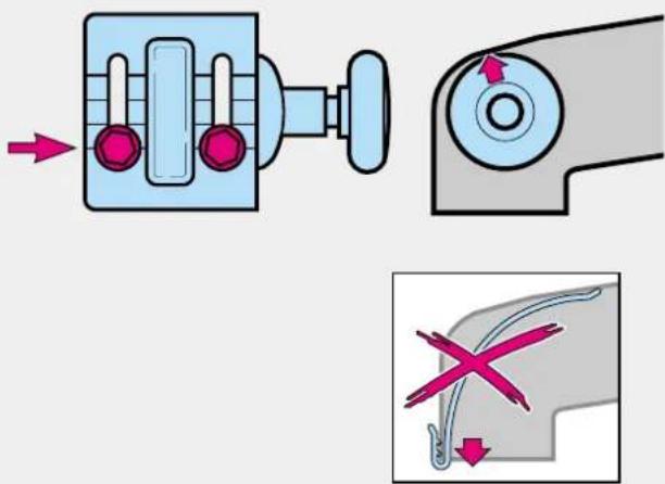
text_image
Diagram illustrating mechanical assembly and disassembly process with labeled components and directional arrows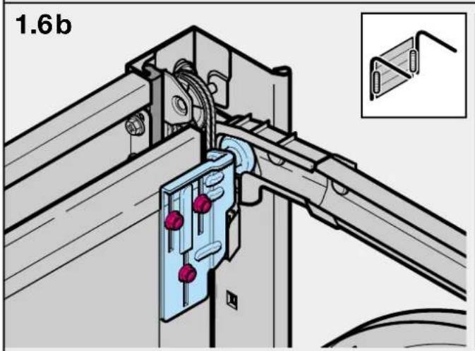
text_image
1.6b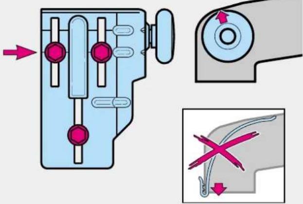
text_image
Diagram illustrating mechanical assembly with labeled parts and directional arrows, including a close-up of a tool or component.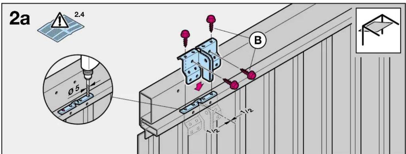
text_image
2a 2.4 Ø5 B 1/2 1/2 1/2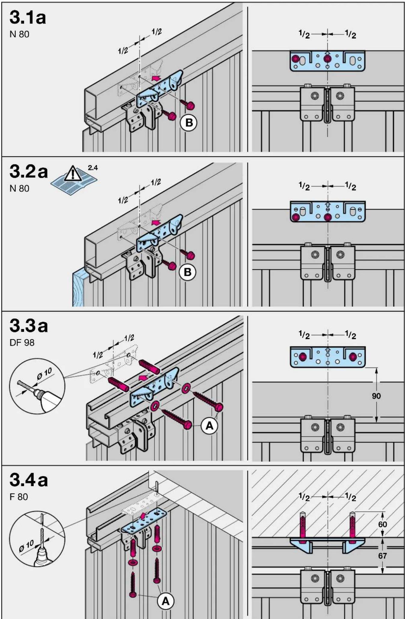
text_image
2b 2.5 Ø 5 B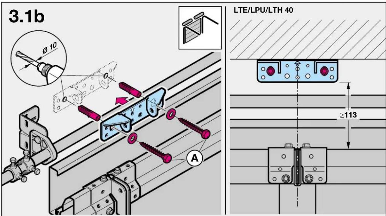
text_image
3.1b LTE/LPU/LTH 40 ≥113 A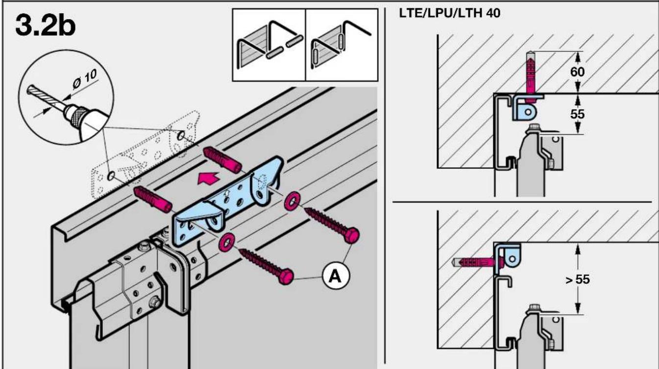
text_image
3.2b LTE/LPU/LTH 40 60 55 >55 A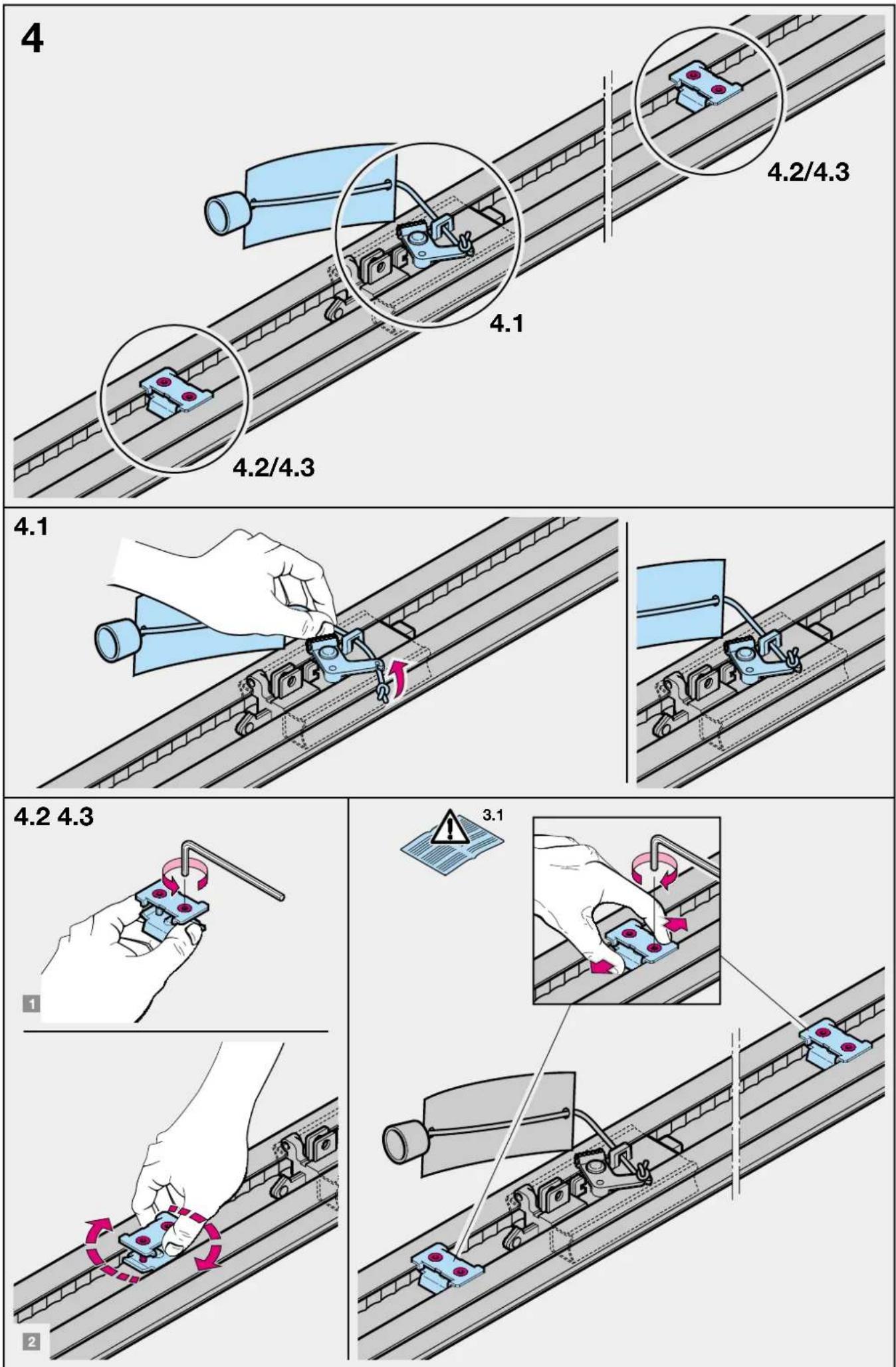
text_image
5 5.1 5.5 5.2-5.4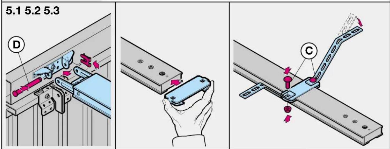
text_image
5.1 5.2 5.3 D C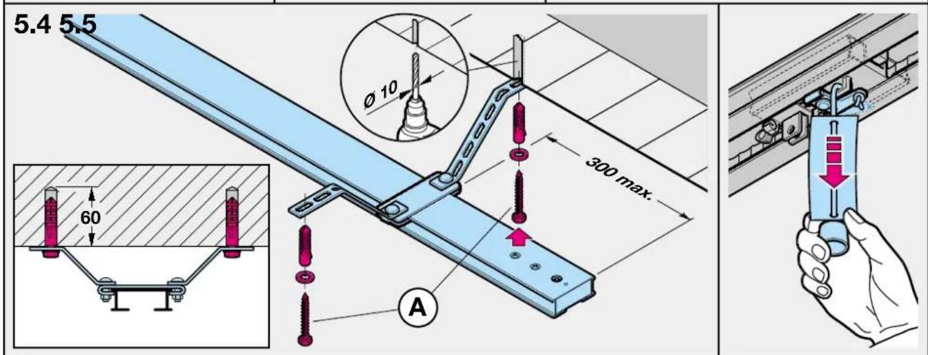
text_image
5.4 5.5 Ø 10 300 max. 60 A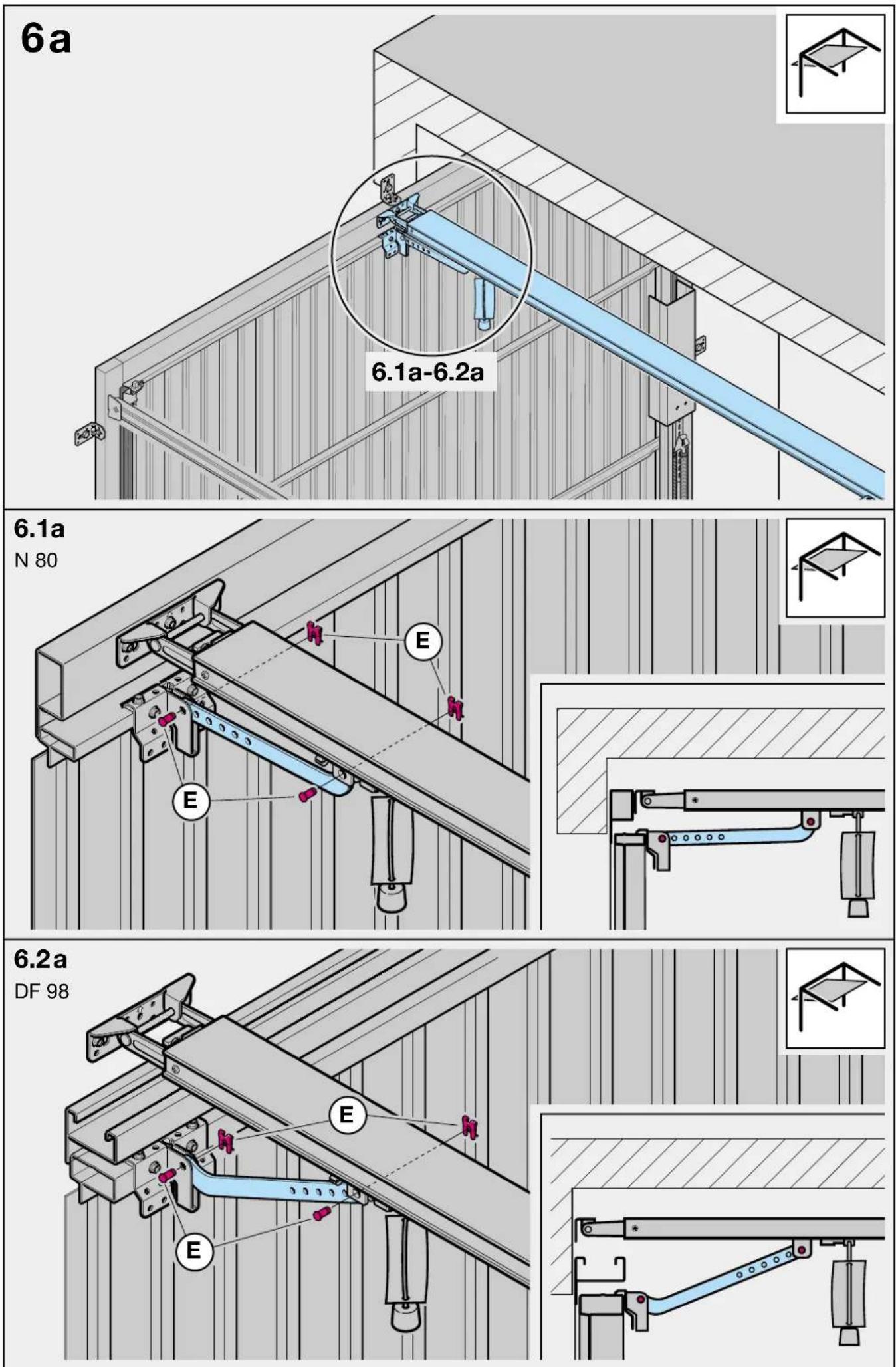
text_image
7 3.1 1 2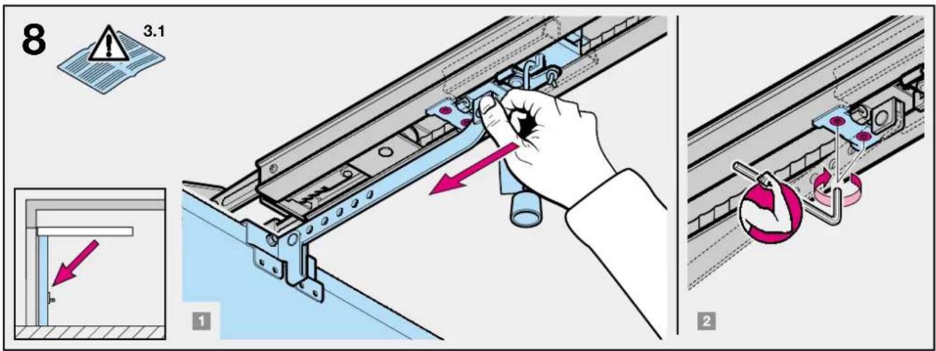
text_image
8 3.1 1 2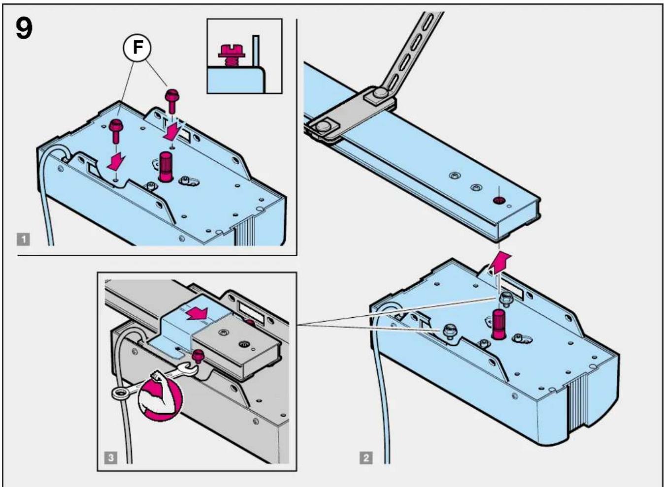
text_image
9 F 1 3 2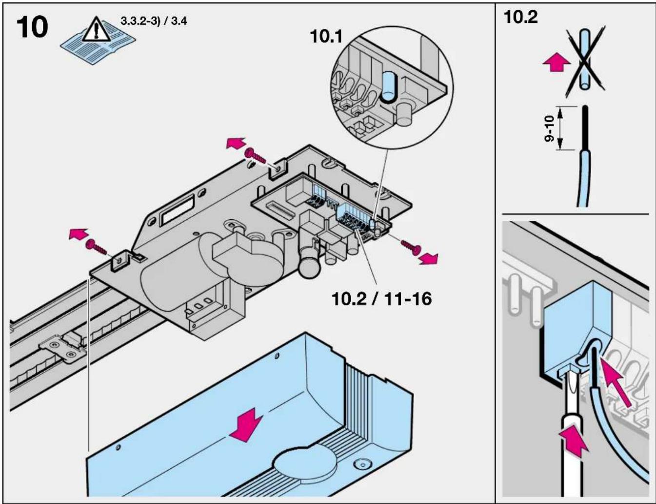
text_image
11 3.5.1 BN WH GN .6 5.8 3 74 202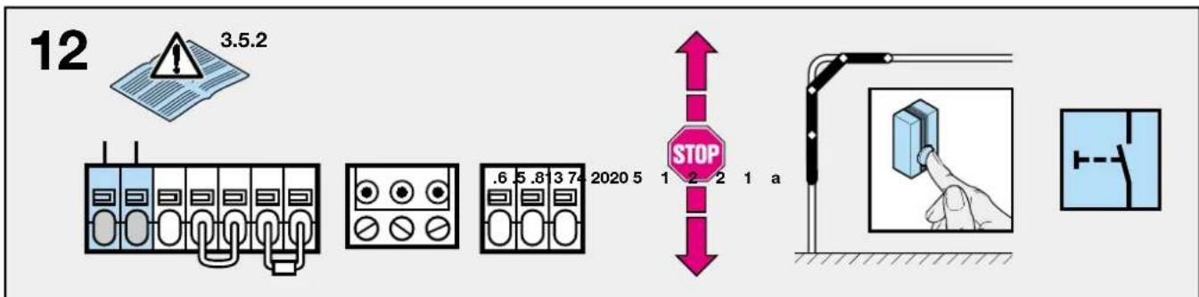
text_image
12 3.5.2 .6 5.8 3 74 2020 5 1 2 2 1 a STOP13
flowchart
graph LR
    A["3.5.3 Sensor"] --> B["Measurement Device 1"]
    A --> C["Measurement Device 2"]
    A --> D["Measurement Device 3"]
    A --> E["Measurement Device 4"]
    A --> F["Measurement Device 5"]
    B --> G["0V Power Supply"]
    C --> G
    D --> G
    E --> G
    F --> G
    G --> H["Oscilloscope Display"]
    H --> I["Analog Signal Display"]
    style A fill:#f9f,stroke:#333
    style H fill:#ccf,stroke:#333
14
text_image
3.5.4 +24V 1 2 3 4 5 0V a A15
text_image
3.5.4 +24V 8.2 kΩ 1 2 1 0V a B16
text_image
3.5.5 .6 5.8 13 7 2020 5 1 2 2 1 a N L117
text_image
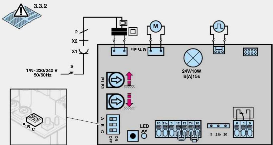
3.3.2 1/N-230/240 V 50/60Hz S X1 X2 2 M M Turbo P1 P2 24V/10W B(A)15s A B C ON LED 20 21a 5 12 13 74 20 5 21b 20 .6 .5 .8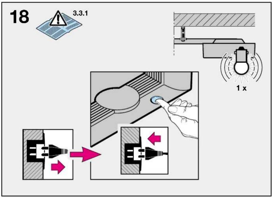
text_image
18 3.3.1 1 x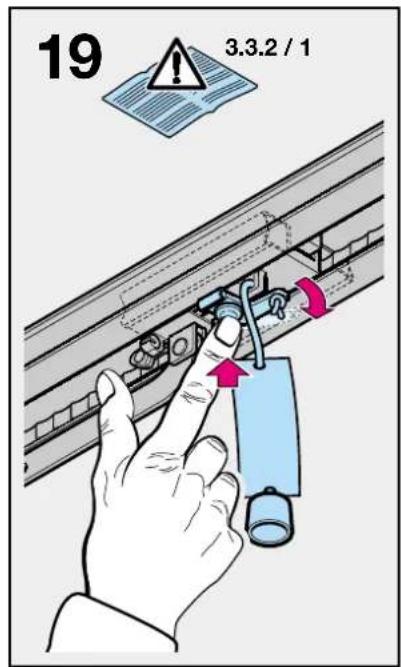
text_image
19 3.3.2 / 1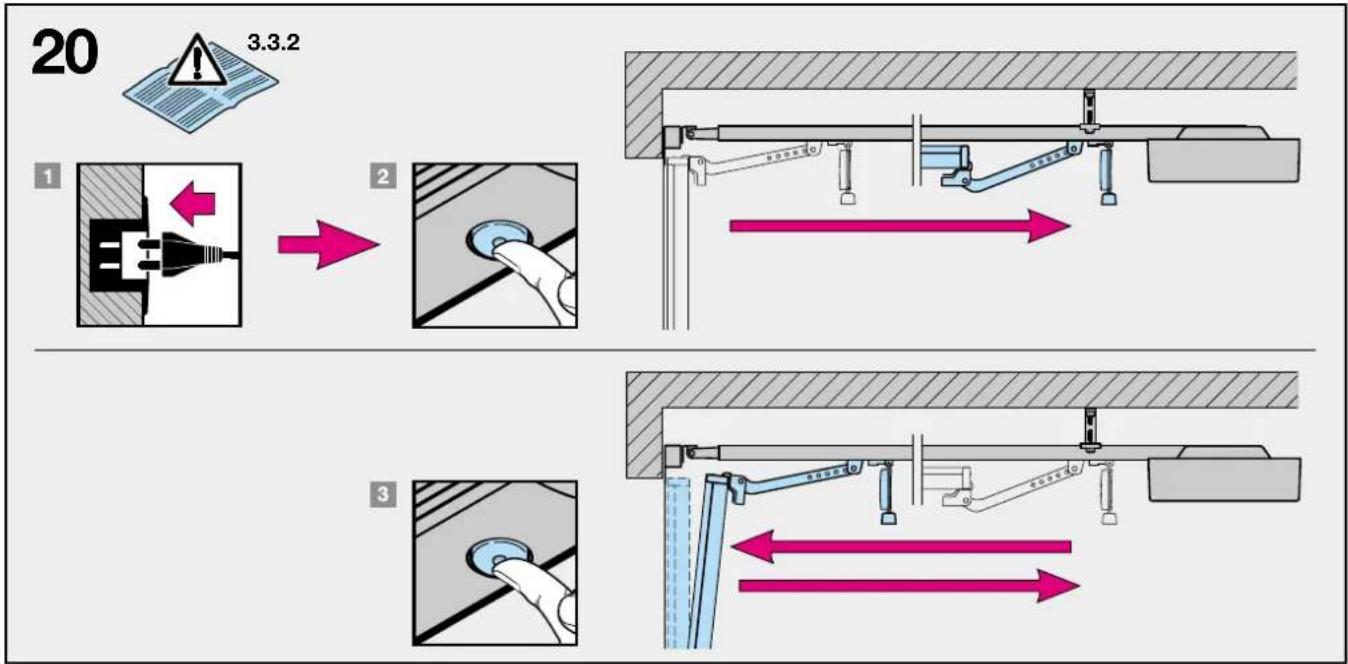
text_image
20 3.3.2 1 2 3
text_image
21.1 3.3.3-4) 21.2 P2 N N P12 Montageanleitung
text_image
Safety warning illustration showing a child sitting on the floor with an upward arrow and warning symbolACHTUNG
text_image
STOP STOP2 Installation Instructions
2.1 Required clearance for installing the operator
When installing the operator, the clearance between the door at its highest point of travel and the ceiling must be at least 30 mm (see figures 1.1a / 1.1b).
2.2 The mechanical door latches on an up-and-over door must be immobilised (see figure 1a). In the case of door models not listed here, the catches must be locked on site.
2.3 On a sectional door the internal mechanical latch must be completely dismantled (see figure 1b).

ATTENTION
When installing the operator, the pull cord on the door must be removed (see figure 1.2b).
2.4 Note
Up-and-over doors with a forged iron door handle
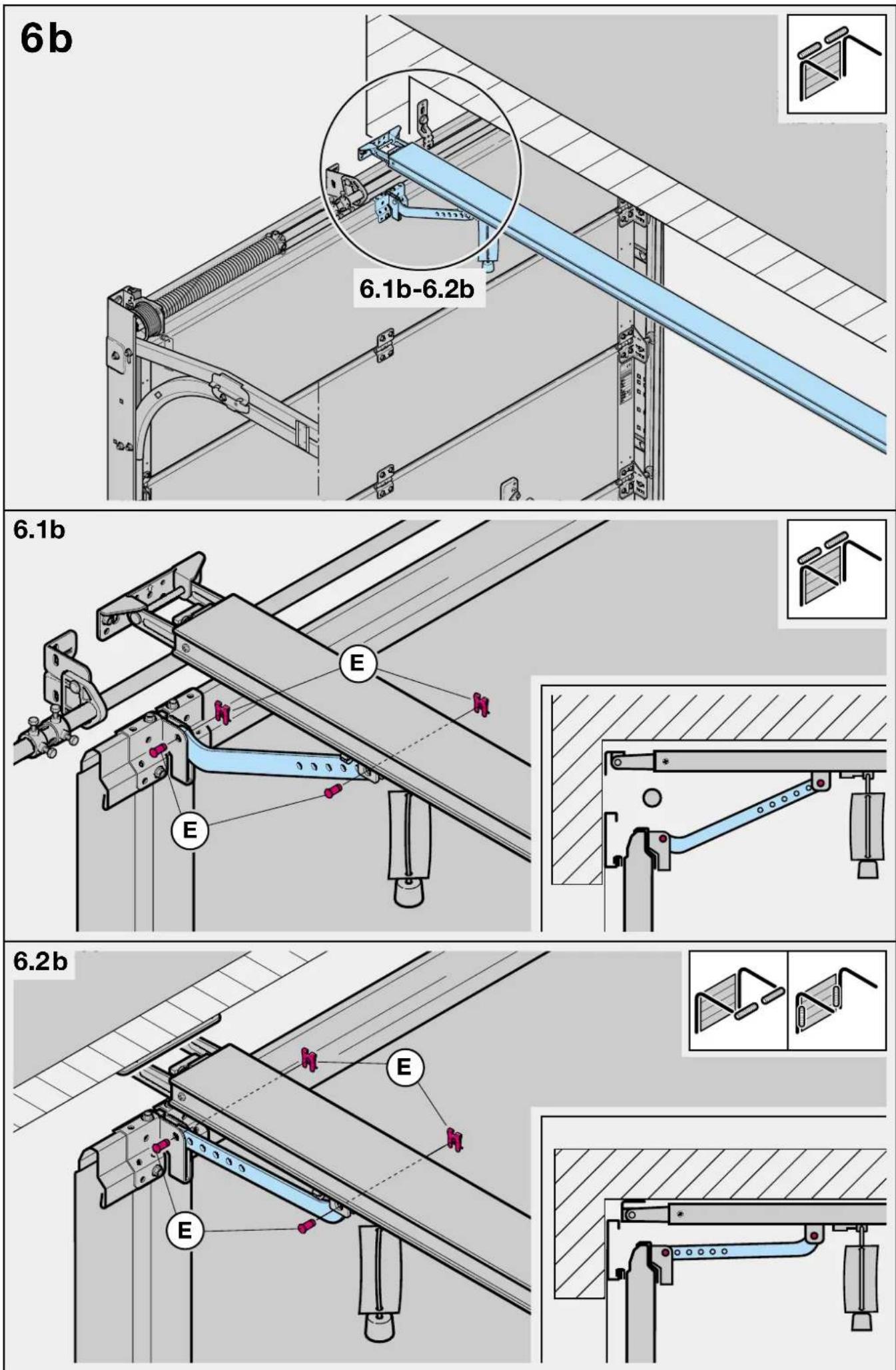
Contrary to the illustrated section (see figure 2a / 3.2a), these doors require the lintel bracket fastening and the door link bracket to be fitted off-centre.
2.5 Central locking on a sectional door
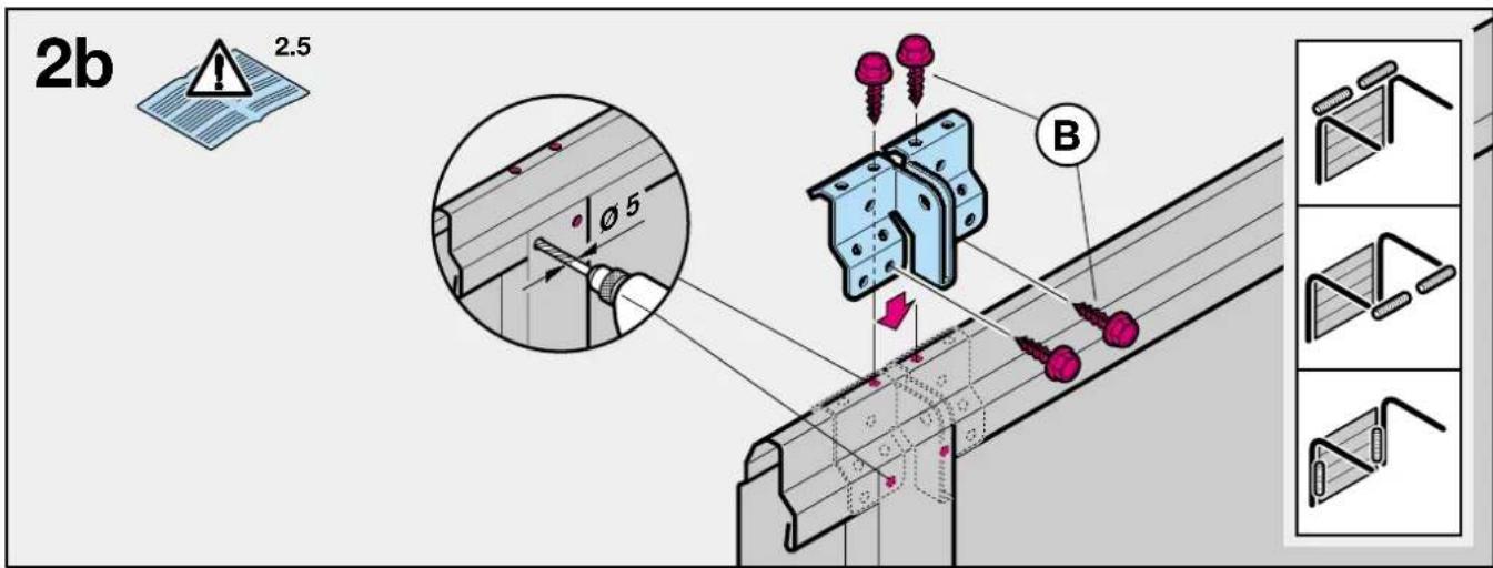
For sectional doors with a centrally positioned lock, fit the lintel bracket fastening and the door link bracket off-centre (see figure 2b).
2.6 Off-centred reinforcement profile on a sectional door
In the case of an off-centred reinforcement profile on a sectional door, fit the door link bracket to the nearest reinforcement profile on the left or right (see figure 2b).
Note
Contrary to the illustrated section, for timber doors use the wood screws 5 x 35 from the pack of screws supplied with the door (3 mm ∅ drill hole).
2.7 Tensioning the drive belt
The operator boom's toothed belt is already set at the factory for optimum tension. During the starting and braking phases of large doors it can happen that the belt hangs out of the boom profile temporarily.
This, however, is of no technical disadvantage nor does it have any negative effect on the operator's function and service life.

CAUTION
Do not insert fingers into the boom while the door is moving risk of crushed fingers!
3 Putting into Service / Connecting Additional Components / Operation
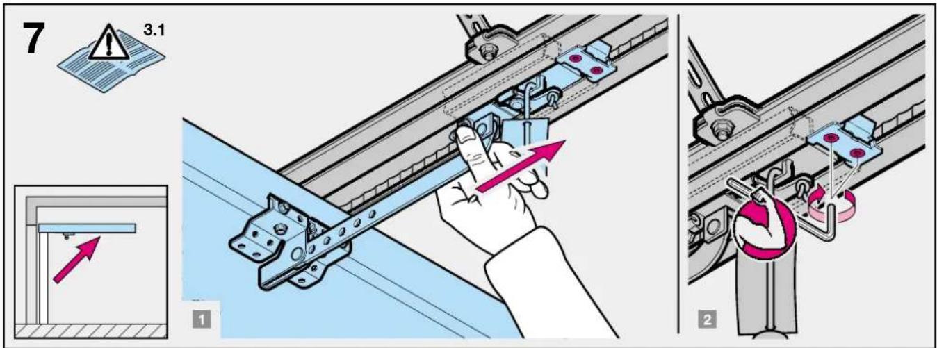
3.1 Establishing the door's end-of-travel positions by installing the limit stops
1) Insert the limit stop for the OPEN end-of-travel loosely into the boom between the carriage and the drive unit
(see figure 4) and after fitting the door link (see figure 6.1a / 6.2a / 6.1b / 6.2b) push the door by hand into the OPEN end-of-travel position → the limit stop is pushed into the correct position (see figure 7).
2) Fix the limit stop for the OPEN end-of-travel position.
3) Insert the limit stop for the CLOSE end-of-travel loosely into the boom between the carriage and the drive unit (see figure 4) and push the door by hand into the CLOSE end-of-travel position → the limit stop is pushed close to the correct position (see figure 8).
4) Push the limit stop for the CLOSE end-of-travel position approx. 1 cm further in the CLOSE direction and then fix in place.
Note
If you are unable to push the door manually into the desired OPEN or CLOSE end-of-travel positions, this indicates that the door mechanics are too sluggish to be used with the garage door operator and must therefore be checked (see section 1.1.2)!
3.2 Notes on work involving electrics

ATTENTION
The following points apply to all work involving electrics:
- Electrical connections may only be made by a qualified electrician!
- Onsite electrical installation must comply with the relevant safety regulations (230/240 V AC, 50/60 Hz)!
- Before working on the operator, always unplug from the mains!
- External voltage at any of the controls connecting terminals will completely destroy the electronics (exception terminal .6, .5, .8)!
- To avoid malfunctions, ensure that the control cables of the operator (24 V DC) are laid in an installation system separate to other supply lines (230 V AC)!
3.3 Putting the operator into service
The operator features a memory (fail-safe even in the event of a power failure) where the data specific to the door (distance of travel, necessary forces for door movement etc.) laid down during learn cycle (programming) are stored and which are updated during subsequent travel cycles. This data is only applicable to this particular door. If any other door is to be used or if the running action of the door has greatly changed (e.g. after subsequently adjusting limit stops or fitting new springs etc.), the data must be deleted and the operator then reprogrammed.
3.3.1 Deleting the door data (see figure 18)
In the ex factory state, the door data is deleted and the operator can be immediately programmed → see section 3.3.2 - Programming the operator.
If re-programming is desired or becomes necessary, the door data can be deleted as follows:
ENGLISH
1) Unplug from the mains.
2) Press the transparent button in the housing and keep depressed.
3) Insert the mains plug and keep the above-mentioned button depressed until the operator lighting flashes. If it only flashes once, the door data has been deleted. You can then proceed with reprogramming immediately.
Note
Further signals from the operator lighting (flashes repeatedly on inserting the mains plug) are explained in section 3.6.3.
3.3.2 Programming the operator
During programming the travel path and the required forces for opening and closing are programmed or stored (data retained even in the event of a power failure). Before the operator can be programmed, the door data must be deleted (see section 3.3.1) and the carriage engaged:
1) If necessary, the disengaged carriage must be prepared for engagement by pressing the green button (see figure 19) on the carriage and the door must be moved by hand until the carriage engages in the belt lock.
2) If necessary, insert the mains plug, the operator lighting then flashes twice (see section 3.6.3).
3) If necessary, use the DIL-switch "C" (accessible on removing the operator cover, see figure 10 and 17) to set the desired behaviour of the closing door on approaching the CLOSE end-of-travel position:
- set DIL-switch "C" to OFF to change over to short "soft" stop for sectional doors (factory setting).
- set DIL-switch "C" to ON to change over to long "soft" stop for up-and-over doors.
4) Press the transparent button in the operator cover (see figure 20) → the door opens with the operator lighting flashing (OPEN learning cycle) and after reaching the OPEN limit stop and a short reverse (approx. 1 cm) comes to a halt with the operator lighting flashing.
Note
If the OPEN limit stop has not been reached, then the OPEN maximum force is set too low and must be increased (see section 3.3.3). After increasing the OPEN maximum force (max. 1/8th turn per adjustment attempt), press the transparent button to cause the door to travel to the CLOSE end-of-travel position. Stop the door closing before it reaches the CLOSE end-of-travel position by pressing the button again. Then repeat step 4 as explained in section 3.3.2.
5) Press the transparent button again (see figure 20) → the door closes with operator lighting flashing throughout (CLOSE learning cycle), in doing so the carriage must reach the CLOSE limit stop. The operator then immediately causes the door (with operator lighting switched on) to travel to the OPEN end-of-travel position and the door then stays in this position. The operator lighting goes out after 3 minutes.
Note
If the CLOSE limit stop has not been reached, then the CLOSE maximum force is set too low and must be increased (see section 3.3.3). After increasing the CLOSE maximum force (max. 1/8th turn per adjustment attempt), delete the door data (see section 3.3.1) and repeat the programming procedure.
6) At least three uninterrupted travel cycles must be consecutively carried out. In doing so, check that the door has fully reached its closed position (if not, readjust the CLOSE limit stop and re-programme the operator). In addition, check that the door opens fully (the carriage comes to a halt shortly before reaching the OPEN end-of-travel position).
The operator is now programmed ready for operation.
7) Please check the programmed force limit by following the corresponding safety instructions provided in section 3.6!
3.3.3 Setting the maximum forces
The required forces for opening and closing the door which were learned and stored during programming are updated also during the subsequent travel cycles. That's why in the event that the running action of the door gets increasingly sluggish (e.g. spring tension slackens) it is important for safety reasons that these values do not reset themselves indefinitely, as otherwise any necessary manual operation of the door could pose a possible safety risk (e.g. door could crash to the floor).
That's why the maximum forces available for opening and closing the door are pre-set at the factory (potentiometer at intermediate setting) but these can be increased if needed.
The maximum forces set at the potentiometer have a slight effect on the sensitivity of the force limit, since the forces actually needed were stored during the learn cycle.
The forces set at the factory are suitable for operating most standard doors.
For setting the maximum opening and closing forces, a potentiometer is available for each direction, accessible on removing the operator cover and marked P1 and P2 (see figure 21.1 / 21.2).
The maximum force in the OPEN direction can be limited via potentiometer P1; while the maximum force in the CLOSE direction can be limited via potentiometer P2. In doing so, turning clockwise increases the forces, while turning anticlockwise reduces the forces.
Note
It is only necessary to increase the maximum forces preset at the factory (potentiometer at intermediate setting) should the need arise during programming (see section 3.3.2).

ATTENTION: Danger to life! Setting the potentiometer too high can result in serious injuries!
ENGLISH
Reducing the setting is only advisable if a light-moving door is involved, a higher level of safety is desired and "normal" operation is guaranteed (must be established through testing).

ATTENTION
If the potentiometer is set too low, this will put the operator out of action!
Note
Besides having the task of limiting the maximum forces (during the OPEN reference cycle and CLOSE learn cycle and serving as an upper limit for updating), both potentiometers also have a second function:
- P1: during a normal opening cycle over the last centimetres before reaching the OPEN end-of-travel position, P1 assumes the task of the programmed force limit, thereby making it possible to adjust doors which require a greater force at this stage only.
- P2: during a normal closing cycle, after passing the limit, from which point on no reversing takes place (so called reversing limit, located just before reaching the CLOSE end-of-travel position), P2 assumes the task of the programmed force limit, thereby making it possible to adjust doors which require a greater force at this point to ensure tight closing.
3.4 Other adjustment options (Warning phase, Automatic closing, options relay)
With the "A" and "B" DIL-switches (accessible on removing the operator cover, see figure 10 and 17), the following functions of the operator and options relay can be set:
DIL-switch "A" at OFF / DIL-switch "B" at OFF
- Operator / operator lighting: normal function.
- Options relay: the relay picks up with the operator lighting, but without cycling.
Note: Factory setting; Connection of additional external operator lighting (see figure 16).
DIL-switch "A" at OFF / DIL-switch "B" at ON
- Operator / operator lighting: normal function.
- Options relay: the relay picks up on reaching the CLOSE end-of-travel position.
Note: "Close" signal.
DIL-switch "A" at ON / DIL-switch "B" at OFF
- Operator: Warning phase (approx. 2 s) always active.
- Operator lighting: flashes rapidly during warning phase.
- Options relay: cycles rapidly during warning phase; "normal" cycling continues when door in motion.
Note: Connection of an external warning light (without automatic flashing) (see figure 16).
DIL-switch "A" at ON / DIL-switch "B" at ON
- Operator: Warning phase (approx. 2 s) always active. Automatic closing from OPEN end-of-travel position after 30 s open phase and approx. 2 s warning phase.
-
operator lighting flashes rapidly during warning phase
-
Options relay: Relay cycles slowly during the open phase and rapidly during the warning phase; "normal" cycling continues when door in motion.
Note: Connection of an external warning light without automatic flashing (see figure 16).
Explanation:
Warning phase
The time from when the command to move is given until the door starts to move. If a new command is given during this time, the warning phase ends without being followed by a subsequent travel cycle.
Open phase
The time the door waits at the OPEN end-of-travel limit. If a command to move is given during this time, the open phase starts anew.
Automatic closing
The door automatically closes after a set time after reaching the OPEN end-of-travel position. Pre-requisite is the fitting of a photocell and/or closing edge safety device!
3.5 Connecting the additional components

Notes on work involving electrics - Attention! The following points apply to all work involving electrics:
- Electrical connections may only be made by a qualified electrician!
- On-site electrical installation must comply with the relevant safety regulations (230/240 V AC, 50/60 Hz)!
- Before working on the operator, always unplug from the mains!
- External voltage at any of the controls connecting terminals will completely destroy the electronics (exception terminal .6, .5, .8)!
- To avoid malfunctions, ensure that the control cables of the operator (24 V DC) are laid in an installation system separate to other supply lines (230/240 V AC)!
To connect the additional components, the operator cover must be removed (see figure 10). The terminals to which the remote control or additional components such as potential-free internal and external buttons, OFF-switch or wicket door contact as well as safety devices such as photocell or closing edge safety device are connected, carry a safe low voltage of only 30 V DC max.
All connecting terminals are designed for multiple occupancy, however, please observe the maximum of 1 x 1.5 mm ^2 (see figure 10.2). Before connection, always pull out the mains plug!
3.5.1 Connecting the remote control
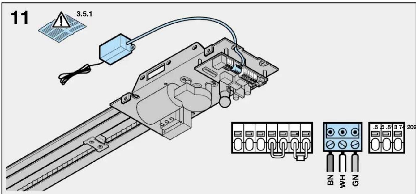
The remote control is to be connected as follows: Plug-in connection (see figure 11)
The receiver unit plug is plugged into the corresponding plug-in location on the operator head.
ENGLISH
When a hand transmitter / receiver set is included, the top button on the hand transmitter is generally already programmed into the receiver.
For information on how to programme in hand transmitter buttons on other receivers, please refer to the instructions supplied with the receiver.
Note
Completely unroll the aerial wire and fasten to the garage ceiling, if possible upwards as well as diagonally in the direction of the structural opening. In doing so, do not wind the aerial wire around metal parts such as nails, braces etc. The best alignment to achieve an optimum range must be established by trial and error.
868 MHz: GSM 900 mobile phones used at the same time may influence the range of the radio remote control.
3.5.2 Connecting external IMPULSE buttons to start or stop door travel cycles
One or several buttons with normally open (n.o.) contacts (potential-free), such as internal buttons or key switches, are connected (in the case of the latter, then joined parallel) as follows (see figure 12):
1) first contact to terminal 21a (impulse input).
2) second contact to terminal 20 (0 V).
Note
If an auxiliary voltage is needed for an external button, then a voltage of approx. +24 V DC is available for this at terminal 5 (as opposed to 0 V at 20), whereby the total current drawn off at terminal 5 must not exceed 100 mA.
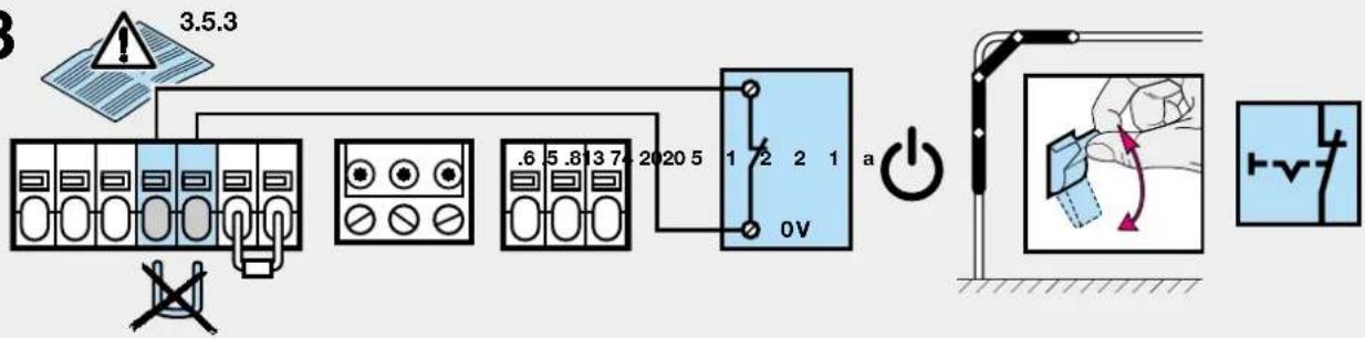
3.5.3 Connecting an OFF-switch or a wicket door contact (opening must be forcibly actuated) to halt and/or switch off the operator (STOP or emergency-OFF circuit)
An OFF-switch with normally closed (n.c.) contacts (switching to 0 V or potential-free) is connected as follows (see figure 13):
1) The jumper inserted at the factory between terminal 12 (STOP or emergency-OFF input) and terminal 13 (0 V), allowing normal function of the operator, should be removed.
2) - Switching output or first contact at terminal 12 (STOP or emergency-OFF input). - 0 V (Ground) or second contact to terminal 13 (0 V).
Note
By opening the contact any possible travel cycles are immediately halted and permanently prevented.
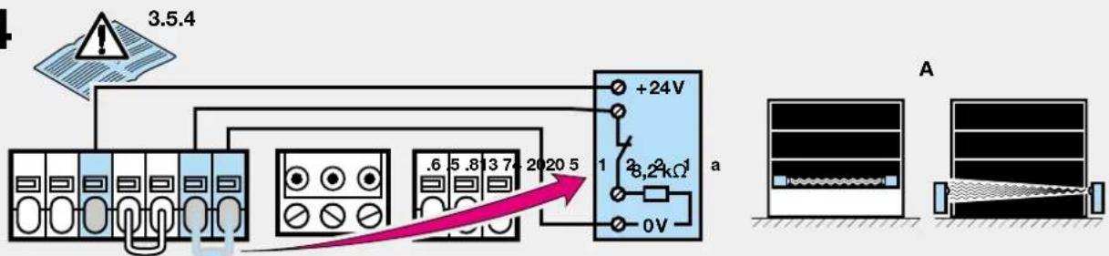
3.5.4 Connecting a photocell or a closing edge safety device to initiate a safety return up to the OPEN end-of-travel position
Option A:
A photocell or closing edge safety device of type A (everything okay = contact closed) switching to 0 V or having a potential-free contact, is connected as follows (see figure 14):
1) The resistance of 8.2 kΩ inserted at the factory between terminals 74 (safety device-input SE) and 20 (0 V) must be removed and then reinserted in the safety device, as shown, between the switching output and terminal 74.
2) 0 V (Ground) or second contact to terminal 20 (0 V).
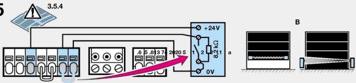
Option B:
A photocell or closing edge safety device of type B (everything okay = contact opened) switching to 0 V or having a potential-free contact, is connected as follows (see figure 15):
1) The resistance of 8.2 kΩ inserted at the factory between terminals 74 (safety device-input SE) and 20 (0 V) must be removed and reinserted in the safety device, as shown. The switching output is connected to terminal 74.
2) 0 V (Ground) or second contact to terminal 20 (0 V).
Note
If an auxiliary voltage is needed for the safety device, then a voltage of approx. +24 V DC is available for this at terminal 5 (as opposed to 0 V at 20), whereby the total current drawn off at terminal 5 must not exceed 100 mA.
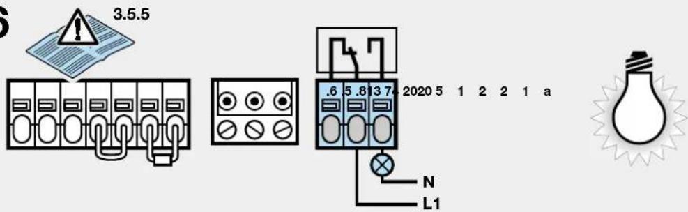
3.5.5 Connecting to the options relay
The potential-free contacts of the options relay allow connection, for example, an external light or a warning light without automatic flashing (see figure 16).
To feed an external light, external voltage must be used!
| Terminal .6 | n.c. contact max. contact | 2,5 A / 30 V DC500 W / 250 V AC |
| Terminal .5 | common contact load: | |
| Terminal .8 | n.o. contact |
Note
The voltage of +24 V DC available at terminal 5 cannot be used to feed an external light!
3.6 Notes on operating the garage door operator
Note
Initial function checks as well as programming or extending the remote control should always take place from inside the garage.
Only ever operate the garage door operator when you have full view of the movement range of the door. Wait until the door has come to a complete halt before entering the door's movement zone.
Before driving in or out of the garage, always check that the door has fully opened.
text_image
Safety warning illustration showing a child sitting on the floor with an upward arrow and warning symbolATTENTION
Keep hand transmitters out of the reach of children!
ENGLISH
The function of the mechanical release should be checked every month. The pull cord with knob may only be actuated when the door is closed, otherwise in the case of weak, broken or defective springs or due to a deficient / faulty counterbalance, there is a risk that the door could close extremely quickly.

ATTENTION
Never hang bodily from the pull cord!
text_image
STOP STOPAll persons using the door system must be shown how to operate the garage door opener properly and safely. Demonstrate and test the mechanical release as well as the safety return. To do this, halt the closing door by grasping it with both hands. The door system should gently cut-out and initiate the safety return. The same should happen during the opening cycle, i.e. the door system gently cuts out and the door comes to a halt.
3.6.1 Normal operation
During normal operation the garage door operator works exclusively on impulse sequence, whereby it makes no difference whether the external button, a programmed hand transmitter button or the transparent button was pressed:
1st Impulse: Operator causes door to move towards an end-of-travel position.
2nd Impulse: Operator causes door to stop.
3rd Impulse: Operator causes door to travel in the opposite direction.
4th Impulse: Operator causes door to stop.
5th Impulse: Operator causes door to travel in the direction of the end-of-travel position selected when the first impulse was generated
etc.
The operator lighting comes on when the door moves and automatically goes out 3 minutes later on completion of the cycle.
3.6.2 Operation following actuation of the mechanical release
If, for instance due to a power failure, the mechanical release was actuated, the carriage must be re- engaged in the belt lock before normal operation can be resumed:
1) Move the operator until the belt lock in the boom is well accessible for the carriage, and then stop the operator.
2) Press the green button on the carriage (see figure 19).
3) Move the door by hand until the carriage re- engages in the belt lock.
4) Carry out several uninterrupted travel cycles to check whether the door has fully reached its closed position and whether it has also fully opened (the carriage comes to a halt shortly before the OPEN limit stop).
The operator is now ready to resume normal operation.
Note
If, after carrying out several uninterrupted travel cycles, the behaviour/action does not correspond to that described in stage 4, a new learn operation will be necessary (see section 3.3.2).
3.6.3 Signals from the operator lighting
If the mains plug is inserted without the transparent button (with operator cover removed the circuit board button) being pressed, the operator lighting flashes two, three or four times.
Flashing twice
indicates that no door data is stored or has been deleted (as in the ex factory state): programming can then be carried out immediately.
Flashing three times
indicates that door data is stored but that the last door position is not sufficiently well known. The next travel cycle is therefore an OPEN reference cycle. This is then followed by "normal" travel cycles.
Flashing four times
indicates that not only is door data stored but also that the last door position is sufficiently well known, so that "normal" travel cycles taking into consideration the impulse sequence (OPEN-STOP-CLOSE-STOP etc.) can follow (normal behaviour following successfully completed programming and a power failure). For safety reasons, whenever there is a power failure during a travel cycle, i.e. when the door is still in motion, the first impulse command always results in the door opening.
Note
An OPEN reference cycle can be enforced if, when the mains plug is inserted, the external button (connected at terminals 20 and 21a) is pressed. In this case, the operator lighting flashes three times.
Replacement lamp for operator lighting: 24 V/10 W, socket: B(a)15s
3.6.4 Error messages / diagnostic LED
(light emitting diode, see figure 10.1)
When operation does not go to plan, a diagnostic LED (visible through the transparent button even with the operator cover in place), helps you to easily identify the possible causes. In the programmed state this LED normally glows constantly and goes out as long as an externally connected IMPULSE device is activated (see section 3.5.2).
Note
On the basis of the behaviour explained above, a short-circuit in the connecting lead of the external button or a short-circuit in the button itself can be recognised even if normal operation of the garage door operator with the remote control or the transparent button is otherwise possible.
LED: flashes 2 x in 4 seconds
Cause: A photocell or closing edge safety device connected to terminals 20 and 74 has been interrupted or activated. It is possible that a safety return has been initiated.
Elimination: Remove the obstruction in question, check the photocell and / or closing edge safety device, and if necessary replace.
Note: If no photocell or closing edge safety device is connected to terminals 20 and 74, check whether the factory assembled resistance of 8,2 kΩ between terminals 20 and 74 is present – if necessary connect.
Acknow-
ledgement: Another impulse is generated via an external button, the remote control or the transparent button – the door travels in the opposite direction to that last travelled.
LED: flashes 3 x in 5 seconds
Cause: The CLOSE force limit has been activated – the door has carried out a safety return.
Elimination: Remove the obstruction. If a safety return has taken place for no recognisable reason, check the door mechanics. It may be necessary to delete the door data and reprogramme.
Acknow-
ledgement: Another impulse is generated via an external button, the remote control or the transparent button – the door opens.
LED: flashes 4 x in 6 seconds
Cause: The STOP or emergency-OFF circuit is open or was opened during a travel cycle (see section 3.5.3)
Elimination: Close the STOP or emergency-OFF circuit (see section 3.5.3)
Acknow-
ledgement: Another impulse is generated via an external button, the remote control or the transparent button – the door travels in the opposite direction to that last travelled.
LED: flashes 5 x in 7 seconds
Cause: The OPEN force limit has been activated – the door has stopped whilst opening.
Elimination: Remove the obstruction. If the door has come to a halt for no recognisable reason, check the door mechanics. It may be necessary to delete the door data and reprogramme.
Acknow-
ledgement: Another impulse is generated via an external button, the remote control or the transparent button – the door closes.
LED: flashes 6 x in 8 seconds
Cause: Operator fault
Elimination: It may be necessary to delete the door data. If the operator fault re- occurs, replace the operator.
Acknow-
ledgement: Generate an impulse via an external button, the remote control or the transparent button – the door opens (OPEN reference cycle).
LED: flashes 7 x in 9 seconds
Cause: The operator has not yet been programmed (this is merely being pointed out – it is not a fault/error).
Elimination/
Acknow-
ledgement: Initiate learn operation for the CLOSE direction via the transparent button.
LED: flashes 8 x in 10 seconds
Cause: The operator requires a reference cycle (this is merely being pointed out – it is not a fault/error).
Elimination/
Acknow-
ledgement: Initiate a reference cycle in the OPEN direction via an external button, the remote control or the transparent button.
Note: This is the normal state following a power failure when no door data is stored or this has been deleted and/or the last door position is not sufficiently well known.
4 Terms and Conditions of the Warranty
Guarantee Period
In addition to the statutory guarantee provided by the dealer, we provide the following guarantee of parts from the date of purchase:
a) 5 years on operator mechanics, motor and motor controls
b) 2 years on radio, impulse generators, accessories and special systems
There is no guarantee on consumables (e.g. fuses, batteries, lighting devices).
Claims made under the guarantee do not extend the guarantee period. Following the supply of replacement parts the guarantee period is six months; or at least, the remainder of the guarantee period.
Conditions
A claim under this guarantee is only valid for the country in which the equipment was bought. The product must have been purchased through authorised distribution channels. A claim under this guarantee exists only for damage to the product in the contract itself. Reimbursement of expenditure for dismantling and installation, testing of corresponding parts, as well as demands for lost profits and compensation for damages, are excluded from the guarantee. The receipt of purchase substantiates your right to claim under the guarantee.
ENGLISH
Service rendered
For the duration of the guarantee we will eliminate all product defects that are proven to be attributable to material or manufacturing faults. We pledge to provide free of charge and at our discretion to replace the defective parts with a non-defective one, to improve it, or to reimburse for a reduction in price.
Excluded are damages due to:
- improper fitting and connection
- improper commissioning or operating
- external influences, such as fire, water, abnormal weather conditions
- mechanical damage due to accidents, dropping, jolting
- negligent or deliberate destruction
- normal wear and tear or deficient maintenance
- repair by non-qualified persons
- use of non-original parts
- removal or making unrecognisable the serial number
Replaced parts become our property.
5 Technical Data
Power supply: 230/240 V, 50/60 Hz
standby approx. 4,5 W
Protection category: For dry rooms only
Automatic cut-out: Automatically programmed separately for both operational directions.
End-of-travel Self-learning, non-wearing, since
cut-out/Force limit: no mechanical switches are used. Additionally integrated excess travel stop of approx. 45 s. Automatic cut-out read-justs itself during each travel cycle.
Rated load: 150 N
Push and pull force: 500 N
Short-time peak load: 650 N
Motor: DC motor with "Hall" sensor
Transformer: With thermal overload protection
Connection:
Connection technique without screws for external equipment with safe low voltage of 24 V DC, e.g. internal and external buttons for impulse control.
Special functions:
- Operator lighting, 3 minutes light factory setting
- STOP/OFF switch can be connected
- Photocell or closing edge safety device can be connected
- Options relay for warning light, additional external lighting
Quick release:
In the event of a power failure, actuated from the inside via a pull cord
Remote control:
2-button hand transmitter HS 2 and separate receiver.
Universal fitting:
For up-and-over and sectional doors
Door speed:
Approx. 14 cm/s (depending on size and weight of door)
Airborne noise emission Garage
≤ 70 dB (A)
Boom:
Extremely flat (no more than 30 mm) with integral door security kit and maintenance-free, patented toothed belt with automatic belt tensioning.
Application:
Exclusively for garages in the domestic sector. For easy-moving up-and-over and sectional doors with a door area of up to 10 m ^2 . Not suitable for industrial / commercial use.
Parking spaces:
Suitable for a maximum of 2 parking spaces
text_image
Safety warning illustration showing a child sitting on the floor with an upward arrow and warning symbolATTENTION
text_image
STOP STOPtext_image
Safety warning illustration showing a child sitting inside a room with an upward arrow and warning symboltext_image
STOP STOPInformeer alle personen, die gebruik maken van de deur, over de reglementaire en veilige bediening van de garagedeuraandrijving. Demonstreer en test de mechanische ontgrendeling en de veiligheidsterugloop.
LED: knippert 2 x in 4 seconden
LED: knippert 3 x in 5 seconden
LED: knippert 4 x in 6 seconden
LED: knippert 5 x in 7 seconden
LED: knippert 6 x in 8 seconden
LED: knippert 7 x in 9 seconden
LED: knippert 8 x in 10 seconden
Transformer: Met thermobeveiliging.