DH 20DV - Drill HITACHI - Free user manual and instructions
Find the device manual for free DH 20DV HITACHI in PDF.
Frequently Asked Questions - DH 20DV HITACHI
User questions about DH 20DV HITACHI
0 question about this device. Answer the ones you know or ask your own.
Ask a new question about this device
Download the instructions for your Drill in PDF format for free! Find your manual DH 20DV - HITACHI and take your electronic device back in hand. On this page are published all the documents necessary for the use of your device. DH 20DV by HITACHI.
USER MANUAL DH 20DV HITACHI
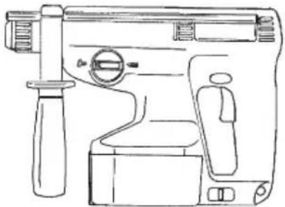
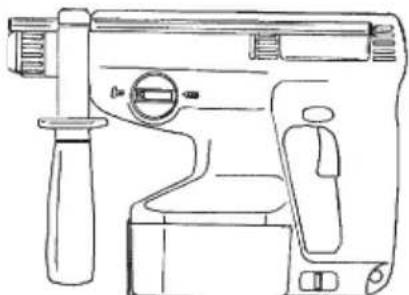
CORDLESS ROTARY HAMMER AKKU-BOHRHAMMER PERFORATEUR PERCUSSION À BATTERIE MARTELLO PERFORATORE A BATTERIA SNOERLOZE BOORHAMER MARTILLO PERFORADOR A BATERÍA MARTELO PERFURADOR A BATERIA ΣΦΥΡΟΔΡΑΠΑΝΟ ΠΕΡΙΣΤΡΟΦΙΚΟ ΜΠΑΤΑΡΙΑΣ
natural_image
Line drawing of a mechanical device with handle, grip, and control panel (no text or symbols)Read through carefully and understand these instructions before use. Diese Anleitung vor Benutzung des Werkzeugs sorgfältig durchlesen und verstehen. Lire soigneusement et bien assimiler ces instructions avant usage. Prima dell'uso leggere attentamente e comprendere queste instruzioni. Deze gebruiksaanwijzing s.v.p. voor gebruik zorgvuldig doorlezen. Leer cuidadosamente y comprender estas instrucciones antes del uso. Antes de usar, leia com cuidado para assimilar estas instruções. Διαβάστε προσεκτικά και κατανοήσετε αυτές τις οδηγίες πριν τη χρήση.
Handling instructions Bedienungsanleitung Mode d'emploi Instruzioni per l'uso Gebruiksaanwijzing Instrucciones de manejo Instruções de uso Οδηγίες χειρισμού
text_image
Technical diagram of a device with labeled parts, showing internal components and part views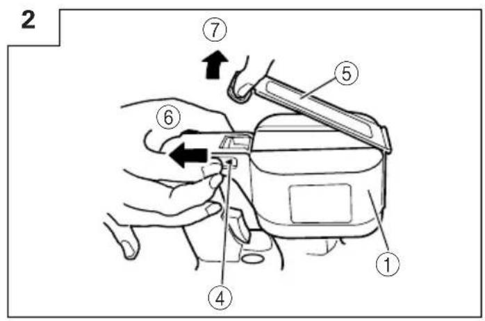
text_image
2 ⑦ ⑤ ⑥ ④ ①
text_image
3 ⑨ ① ⑧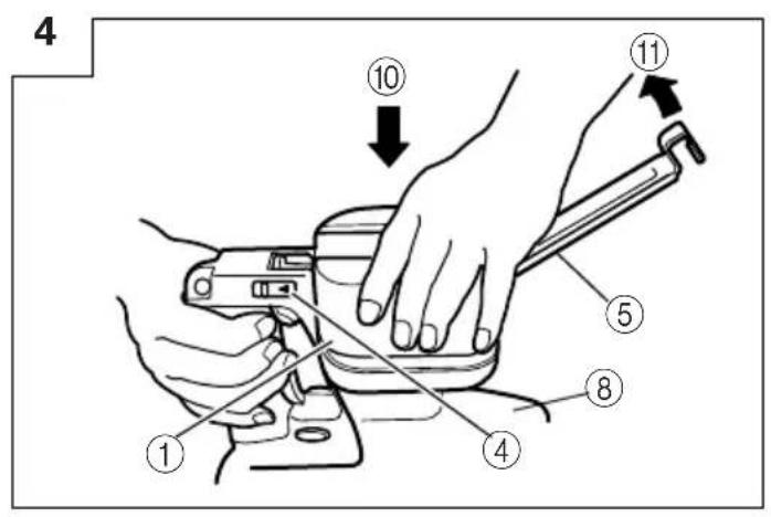
text_image
4 ① ④ ⑧ ⑤ ⑪ ⑩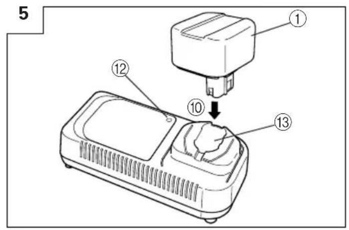
text_image
5 ① ⑫ ⑩ ⑬ ⑬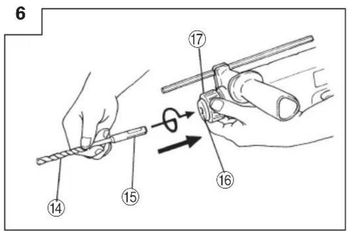
text_image
6 14 15 17 16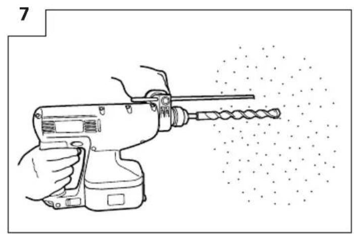
natural_image
Line drawing of a hand using a drill press to shoot material, with no text or symbols present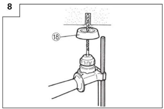
text_image
8 ⑱9
text_image
⑲10
text_image
Technical diagram of a vehicle air intake system with numbered components and directional arrows indicating flow or movement.11
text_image
[③5] (a) ②7 30 ③1 33 ③4 26 (b) ②8 26 32 (c) ②912
text_image
36 37 15 → 17 1613
text_image
Technical diagram of a mechanical device with numbered parts and directional arrows indicating motion or flow.14
text_image
Diagram showing a hand holding a key to a component, with numbered parts labeled 16, 17, 37, 42, and 41.15
text_image
Technical diagram showing the assembly of a drill bit with numbered parts and a close-up view of the component.16
text_image
Technical diagram showing a hammer striking a drill bit with labeled parts 43, 44, and 45| English Deutsch | Français Italiano | |||
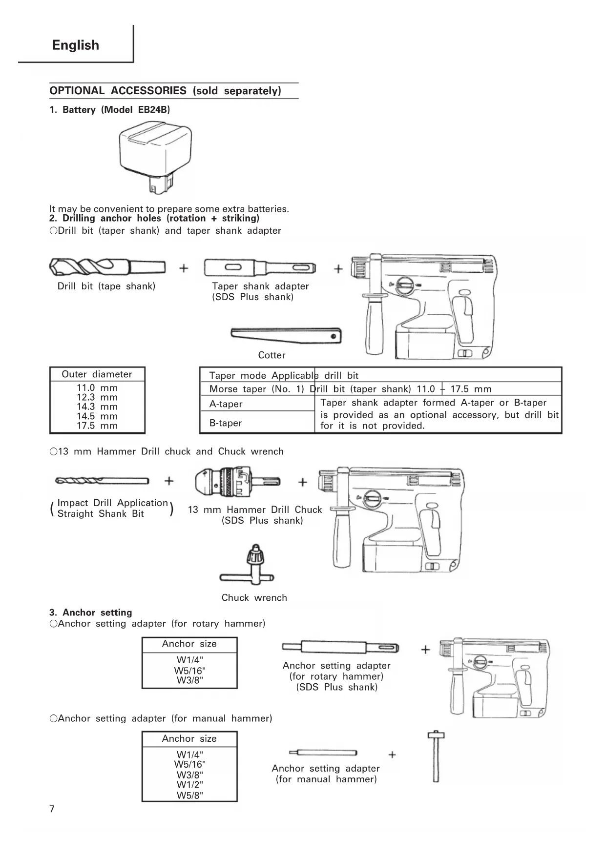
| 1 | Rechargeable battery Batterie Batterie rechargeable Batterie ricaricabile | |||
| 2 | Battery cover Batterieabdeckung Couvercle de batterie Batteria di sconta | |||
| 3 | Name plate of battery Type inschild der Batterie Plaque nominale de la batterie Etichetta della batteria | |||
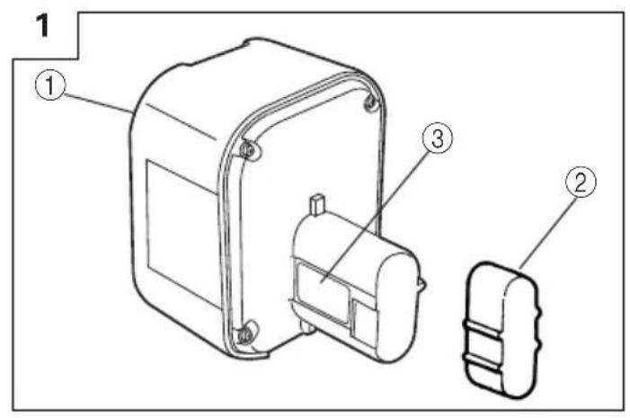
| 4 | Slide lever Gleithebel Levier coulissant Leva scorrevole | |||
| 5 | Plate ass'y Blechmontage Ensemble de plaque Gruppop piastra | |||
| 6 | Pull Ziehen | Tirer | Tirare | |
| 7 | Open | Öffnen | Ouvrir | Aprire |
| 8 | Body | Gehäuse | Corps | Corpo |
| 9 | Pull out Herausziehen | Tirer vers l'extérieur Estrarre | ||
| 10 | Insert | Einsetzen | Insérer | Inserire |
| 11 | Close | Schließen | Fermer | Chiudere |
| 12 | Pilot lamp | Kontrollampe | Lampe témoin Spia | |
| 13 | Hole for connecting the rechargeable battery | Anschlußloch für Batterie | Orifice de raccordement de la batterie rechargeable | Foro di collegamento della batteria ricaricabile |
| 14 | Drill bit | Bohrer | Foret de perçage Punta del | trapano |
| 15 | Part of SDS-plus shank | Teil des SDS-plus Schaftes | Elément de la tige SDS plus | Parte dell'asta SDS plus |
| 16 | Front cap | Vordere Abdeckung | Capuchon avant | Protezione davanti |
| 17 | Grip | Spannbacke | Attache coulissante | Presa davanti |
| 18 | Dust cup | Staubschale | Godet a poussière | Contenitore a polvere |
| 19 | Dust collector (B) | Staubfang (B) | Collecteur à poussière (B) | Camera a polvere (B) |
| 20 | Change lever | Wechselknopf | Bouton de changement | Rotella di cambio |
| 21 | "►" mark | "►" zeichen | Repère "►" | Contrassegno "►" |
| 22 | "T" mark | "T" zeichen | Repère "T" | Contrassetgno "T" |
| 23 | "◄" mark | "◄" zeichen | Repère "◄" | Contrassegno "◄" |
| 24 | "Rotation + Striking" mode | Betriebsart "Schlagbohren" | Position "Rotation + Percussion" | Modo "rotazione e battimento" |
| 25 | "Rotation only" mode | Betriebsart "Bohren" | Position "Rotation seulement" | Mode "solo rotazione" |
| 26 | Push botton | Druckknopf | Poussoir Tasto da premere | |
| 27 | Forward rotation | Vorwärtsdrehung | Rotation avant | Rotazione in avanti |
| 28 | Reverse rotation | Rückwärtsdrehung | Rotation inverse | Rotazione indietro |
| 29 | Does not rotate | Keine Drehung | Aucune rotation | Non ruota |
| 30 | Push the (R) side | Die (R) Seite drücken | Pousser sur le côté (R) | Spingere il lato (R) |
| 31 | Push the (L) side | Die (L) Seite drücken | Pousser sur le côté (L) | Spingere il lato (L) |
| 32 | Center position | Mittenposition | Position médiane | Posizione centrale |
| 33 | (R) indication | (R) Anzeige | Indication (R) | Indicazione (R) |
| 34 | (L) indication | (L) Anzeige | Indication (L) | Indicazione (L) |
| 35 | Diagram seen from the handle side | Die Zeichnung ist von der Handgriffseite aus gesehen. | Schéma, côté poignée | Diagramma visto dal lato della maniglia |
| 36 | Drill chuck | Bohrfutter Mandrin porte-feret Mandrino | ||
| 37 | Chuck adaptor | Bohrutteradapter | Raccord de mandrin | Adattatore per mandrino |
| 38 | Depth gauge | Tiefenmesser | Jauge de profondeur | Calibro profondità |
| 39 | Mounting hole | Befestigungsöffnung | Orifice de montage | Foro d'inserimento della bacchetta di arresto |
| 40 | Side handle | Handgriff | Poignée laterale | Laterale |
| 41 | Bit | Bohrerspitzen | Mèche | Punta |
| 42 | Socket | Fassung | Prise | Presa |
| 43 | Taper shank adapter | Kegelschaftadapter | Raccord de queue conique | Adattatore per gambo conico |
| 44 | Cotter | Dorn | Clavette | Coppiglia |
| 45 | Rest | Auflage Support | Appoggio | |
| Nederlands Español | Português Ελληνικά | |||
| 1 | Oplaadbare batterij Bateria | recargable Bateria recarregável | Επαναφορτιζόμενη μπαταρία | |
| 2 | Accu-afdekking Cubierta de | la batería Tampa da bateria | Κάλυμμα μπαταρίας | |
| 3 | Naamplaatje van de batterij | Placa de características de la batería da bateria | Placa de identificação | Πινακίδα μπαταρίας |
| 4 | Schuifhendel Palanca desliz | able Alavanca deslizante Oλισθαίνων μοχλός | ||
| 5 | Plaatmontage Conjunto de | la placa Conjunto de placa | Πλαισιο συναρμολόγησης | |
| 6 | Pull Ziehen Puxar | Τραβήξετε | ||
| 7 | Open | Abrir | Abrir | Ανοίξετε |
| 8 | Behuizing | Cuerpo | Corpo | Κορμός |
| 9 | Uittrekken | Sacar | Retirar | Τραβήξετε έξω |
| 10 | Insteken | Insertar | Inserir | Εισχωρήστε |
| 11 | Sluiten | Cerrar | Fechar | Κλείστε |
| 12 | Kontrolelampje | Lámpara piloto | Lâmpada piloto | Δοκιμαστική λάμπα |
| 13 | Aansluiting voor oplaadbare batterij | Agujero para conectar la batería racargable | Orificio para conectar a bateria recarregável | Τρύπα για την σύνδεση της επαναφορτιζόμενης μπαταρίας |
| 14 | Boorstuk | Broca | Broca | Λεπίδα τρυπανιού |
| 15 | Onderdeel van SDS Plus schacht | Parte del SDS más vástago | Cabo de peça SDS-plus | Τμήμα του SDS-plus στελέχους |
| 16 | Voorkap | Cubierta frontal | Tampa da frente | Μπροστινό περίβλημα |
| 17 | Greep | Sujetador Mordente | Λαβή | |
| 18 | Stofvangkap | Copa de polvo | Receptáculo para poeira | Κύπελλο σκόνης |
| 19 | Stofverzamelaar (B) | Colector de polvo (B) | Coletor de poeira (B) | Συλλέκτης σκόνης (B) |
| 20 | Omstelknop | Perilla de cambio | Seletor | Μοχλός αλλαγής |
| 21 | “►”-markering | Marca “►” | Marca “►” | “►” σημάδι |
| 22 | “T”-markering | Marca “T” | Marca “T” | “T” σημάδι |
| 23 | “∞”-markering | Marca “∞” | Marca “∞” | “∞” σημάδι |
| 24 | “Draaien en kloppen” stand | Modo de “Rotación + Impacto” | Modo “Rotação + Martelada” | Τρόπος λειτουργίας “Περιστροφή + Κτύπημα” |
| 25 | “Alleen draaien” stand | Mode de “Rotación solamente” | Modo “Somente Rotação” | Τρόπος λειτουργίας “Περιστροφή μόνο” |
| 26 | Druktoets | Pulsador | Botão de pressão | Κουμπί ώθησης |
| 27 | Voorwaartse draairichting | Rotación hacia la derecha | Rotação para frente | Προς τα εμπρός περιστροφή |
| 28 | Terugwaartse draairichting | Rotación hacia la izquierda | Rotação inversa | Αντίστροφη περιστροφή |
| 29 | Draait niet | No gira | Nenhuma rotação | Δεν περιστρέφεται |
| 30 | Druk aan de (R) kant | Presione el lado (R) | Apertar o lado “(R)” | Σπρώξετε την “(R)” πλευρά |
| 31 | Druk aan de (L) kant Presio | ne el lado (L) | Apertar o lado “(L)” | Σπρώξετε την “(L)” πλευρά |
| 32 | Middenpositie | Posición central | Posição intermediária | Κεντρική θέση |
| 33 | (R) aanduiding Indicación | (R) | Indicação “(R)” | “(R)” ένδειξη |
| 34 | (L) aanduiding | Indicación (L) | Indicação “(L)” | “(L)” ένδειξη |
| 35 | Schema, gezien vanaf de handgreep-kant | Diagrama visto desde el lado del asa | Diagrama visto pelo lado do cabo | Διάγραμμα που βλέπεται από την πλευρά του χερουλιού |
| 36 | Boorkop | Portabrocas | Mandril | Σφικτήρας τρυπανιού |
| 37 | Boorkopadapter | Adaptador del portabrocas | Adaptador do mandril | Προσαρμογέας σφικτήρα |
| 38 | Diepte-maatlat | Calibre de profundidad | Sonda | Μετρητής βάθους |
| 39 | Montagegat | Agujero de montaje | Orificio de montagem | Τρύπα στερέωσης |
| 40 | Zijgreep | Mango lateral | Empunhadura lateral | Πλευρική λαβή |
| 41 | Boorstuk | Broca | Palhetão | Λεπίδα |
| 42 | Aansluithus | Cubo | Encaixe | Υποδοχή |
| 43 | Vernauwde schachtadaptor | Adaptador de la espiga | Adaptador de cabo cônico | Κωνικός προσαρμογέας στελέχους |
| 44 | Cotter | Chaveta | Cavilha | Κόφτης |
| 45 | Steun | Apoyo | Suporte | Στήριγμα |
GENERAL OPERATIONAL PRECAUTIONS
- Keep work area clean. Cluttered areas and benches invite accidents.
- Avoid dangerous environment. Don't expose power tools and charger to rain. Don't use power tools and charger in damp or wet locations. And keep work area well lit. Never use power tools and charger near flammable or explosive materials. Do not use tool and charger in presence of flammable liquids or gases.
- Keep children away. All visitors should be kept safe distance from work area.
- Store idle tools and charger. When not in use, tools and charger should be stored in dry, high or locked-up place-out of reach of children. Store tools and charger in a place where the temperature is less than 40^ C.
- Don't force tool. It will do the job better and safer at the rate for which it was designed.
- Use right tool. Don't force small tool or attachment to do the job of a heavy duty tool.
- Wear proper apparel. Do not wear clothing or jewelry. They can be caught in moving parts. Rubber gloves and footwear are recommended when working outdoor.
- Use eye protection with most tools. Also use face or dust mask if cutting operation is dusty.
- Don't abuse cord. Never carry charger by cord or yank it to disconnect from receptacle. Keep cord from heat, oil and sharp edges.
- Secure work. Use clamps or a vise to hold work. It's safer than using your hand and it frees both hands to operate tool.
- Don't overreach. Keep proper footing and balance at all times.
- Maintain tools with care. Keep tools sharp at all times, and clean for best and safest performance. Follow instructions for lubricating and changing accessories.
- When the charger is not in use, or when being maintained and inspected, disconnect its power cord from the AC outlet.
- Remove chuck wrenches and wrenches. Form habit of checking to see that wrenches are removed from tool before turning it on.
- Avoid accidental starting. Don't carry tool with finger on switch.
- To avoid danger, always use only the specified charger.
- Use only genuine HITACHI replacement parts.
- Do not use power tools for applications other than those specified in the Handling Instructions.
- To avoid personal injury, use only the accessories or attachment recommended in these handling instructions or in the HITACHI catalog.
- Let only the authorized service center do the repairing. The Manufacturer will not be responsible for any damages or injuries caused by repair by the unauthorized persons or by mishandling of the tool.
- To ensure the designed operational integrity of power tools and charger, do not remove installed covers or screws.
- Always use the charger at the voltage specified on the nameplate.
- Do not touch movable parts or accessories unless the battery has been removed.
-
Always charge the battery before use.
-
Never use a battery other than that specified. Do not connect a usual dry cell, a rechargeable battery other than that specified or a car battery to the power tool.
- Do not use any transformer that has a booster.
- Do not charge the battery from an engine electric generator or DC power supply.
- Always charge indoors. Because the charger and battery heat slightly during charging, charge the battery in a place not exposed to direct sunlight; where the humidity is low and the ventilation good.
- When working in a high place, pay attention to the activities below to make sure there are no people below.
- Use the exploded assembly drawing on this handling instructions only for authorized servicing.
PRECAUTIONS FOR CORDLESS ROTARY HAMMER
- These chargers utilize a special charging control system due to the fact that the high charging speed. Therefore, always charge the battery at a temperature of 0–40°C for UC24YF. A lower temperature than these specified ranges will result in overcharging which will shorten the battery life. The battery cannot be charged at a temperature higher than 40°C. The most suitable temperature for charging is that of 20–25°C.
- Do not use the charger continuously. When one charging is completed, leave the charger for about 15 minutes before the next charging of battery.
- Do not allow foreign matter to enter the hole for connecting the rechargeable battery.
- Never disassemble the rechargeable battery and charger.
- Never short-circuit the rechargeable battery. Short-chircuiting the battery will cause a great electric current and overheat. It results in burn or damage to the battery.
- Do not dispose of the battery in fire. If the battery is burnt, it may explode.
- When using this unit continuously, the unit may overheat, leading to damage in the motor and switch. Please leave it without using it for approximately 15 minutes.
- Do not insert object into the air ventilation slots of the charger. Inserting metal objects or inflammables into the charger air ventilation slots will result in electrical shock hazard or damaged charger.
- Using an exhausted battery will damage the charger.
- When drilling in wall, floor or ceiling, check for buried electric power cord, etc.
- Bring the battery to the shop from which it was purchased as soon as the post-charging battery life becomes too short for practical use. Do not dispose of the exhausted battery.
- Wear earplugs to protect your ears during operation.
- Do not touch the bit during or immediately after operation. The bit becomes very hot during operation and could cause serious burns.
- Always hold the body handle and side handle of the power tool firmly. Otherwise the counterforce produced may result in inaccurate and even dangerous operation.
SPECIFICATIONS
POWER TOOL
| Model DH20DV | |||
| No-load speed 0 – 1150/min. | |||
| No-load impact rate 0 – 4400/min. | |||
| Capacity | Drilling | Concrete 20 mm | |
| Steel | 13 mm | ||
| Wood | 27 mm | ||
| Driving | Wood screw | 6.2 mm (diameter) × 40 mm (length) | |
| Rechargeable battery | Ni-Cd battery, 24V | ||
| Weight | 3.7 kg | ||
CHARGER
| Model UC24YF UC24YFA | |||
| Charging time (at 20°C) | EB24B Approx. 60 min. Approx. 50 min. | ||
| Charging voltage 7.2 – 24V 7.2 – 24V | |||
| Weight 1.0 kg 0.6 kg | |||
STANDARD ACCESSORIES
| DH20DV (BFK) |  1Battery cover....12Side handle....13Depth gauge....14Charger....15Plastic case....1 1Battery cover....12Side handle....13Depth gauge....14Charger....15Plastic case....1 |
| DH20DV (2BFK) |  1Battery cover....22Side handle....13Depth gauge....14Charger....15Plastic case....16Extra battery....1 1Battery cover....22Side handle....13Depth gauge....14Charger....15Plastic case....16Extra battery....1 |
Standard accessories are subject to change without notice.
OPTIONAL ACCESSORIES (sold separately)
1. Battery (Model EB24B)
natural_image
Simple line drawing of a rectangular electronic component with a small protruding base (no text or symbols)It may be convenient to prepare some extra batteries.
2. Drilling anchor holes (rotation + striking)
○Drill bit (taper shank) and taper shank adapter
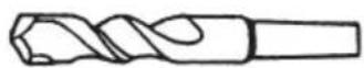
Drill bit (tape shank)

Taper shank adapter (SDS Plus shank)

natural_image
Line drawing of a toilet with handle and seat (no text or symbols)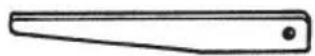
Cotter
| Outer diameter |
| 11.0 mm |
| 12.3 mm |
| 14.3 mm |
| 14.5 mm |
| 17.5 mm |
| Taper mode Applicable drill bit | |
| Morse taper (No. 1) Drill bit (taper shank) 11.0 + 17.5 mm | |
| A-taper | Taper shank adapter formed A-taper or B-taper is provided as an optional accessory, but drill bit for it is not provided. |
| B-taper | |
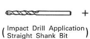
○13 mm Hammer Drill chuck and Chuck wrench
text_image
(Impact Drill Application Straight Shank Bit)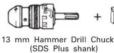
text_image
13 mm Hammer Drill Chuck (SDS Plus shank)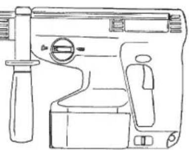
natural_image
Line drawing of a mechanical device with handle and control panel (no text or symbols)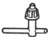
Chuck wrench
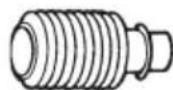
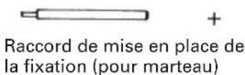
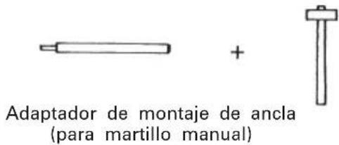
3. Anchor setting
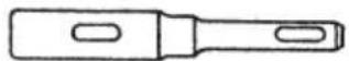
○Anchor setting adapter (for rotary hammer)
| Anchor size |
| W1/4" |
| W5/16" |
| W3/8" |
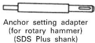
text_image
Anchor setting adapter (for rotary hammer) (SDS Plus shank)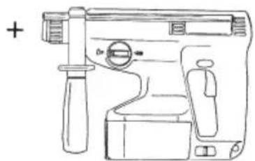
natural_image
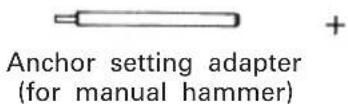
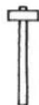
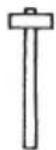
Line drawing of a handheld device with handle and control panel (no text or symbols)○Anchor setting adapter (for manual hammer)
| Anchor size |
| W1/4" |
| W5/16" |
| W3/8" |
| W1/2" |
| W5/8" |
4. Drilling holes and driving screws (rotation only)
○Drill chuck, chuck adapter and chuck wrench
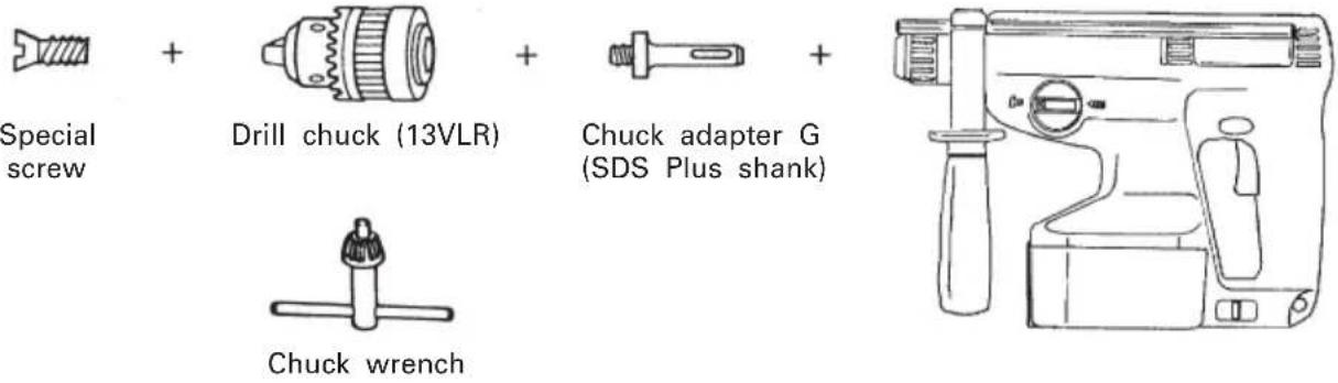
5. Drilling holes (rotation only)
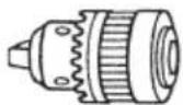
Drill chuck (13VLA)

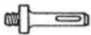

Chuck adapter D (SDS Plus shank)
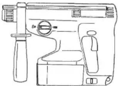
natural_image
Line drawing of a mechanical device with handle and control panel (no text or symbols)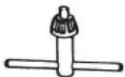
Chuck wrench
☐ 13 mm drill chuck ass'y (include chuck wrench ass'y) and chuck (for drilling in steel or wood).
6. Driving Screws (rotation only)
Bit No.

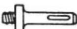

Chuck adapter D (SDS Plus shank)
natural_image
Line drawing of a toilet with handle and side panel (no text or symbols)| Bit No. Screw Size Length | |
| No.2 3-5 mm 25 mm |
7. Dust cup, Dust collector (B)
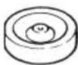
Dust cup
Dust collector (B)
APPLICATIONS
Rotation and striking mode
○Drilling anchor holes
○Drilling holes in concrete
○Drilling holes in tile
Rotation only mode
○Drilling in steel or wood (with optional accessories)
○Tightening wood screws. (with optional accessories)
BATTERY REMOVAL/INSTALLATION
- Turn the body upside down and hold it firmly. Then, open the plate assembly while pulling the slide lever. (Fig. 2) To remove the battery, pull it out while holding the body tightly. (Fig. 3)
- Pay attention to the inserting direction of the battery, insert the battery, and close the plate assembly. When the plate assembly and the slide lever engage each other perfectly, there will be the sound of a click. (Fig. 4)
CHARGING
Before using the power tool, charge the battery as follows.
- Connect the charger's power cord to the receptacle.
When the power cord is connected, the charger's pilot lamp will blink in red. (At 1-second intervals.)
- Insert the battery into the charger.
Firmly insert the battery into the charger till it contacts the bottom of the charger after checking the polarities as shown in Fig. 5.
CAUTION:
○If the battery is inserted in the reverse direction, not only recharging will become impossible, but it may also cause problems in the charger such as a deformed recharging terminal.
- Charging
When inserting a battery in the charger, charging will commence and the pilot lamp will light continuously in red. When the battery becomes fully recharged, the pilot lamp will blink in red. (At 1-second intervals.) (See Table 1)
(1) Pilot lamp indication
The indications of the pilot lamp will be as shown in Table 1, according to the condition of the charger or the rechargeable battery.
Table 1
| Indications of the pilot lamp | |||
| Before charging | Blinks (RED) | Lights for 0.5 seconds. Does not light for 0.5 seconds. (off for 0.5 seconds) | |
| While charging | Lights (RED) | Lights continuously | |
| Charging complete | Blinks (RED) | Lights for 0.5 seconds. Does not light for 0.5 seconds. (off for 0.5 seconds) | |
| Charging impossible | Flikers (RED) | Lights for 0.1 seconds. Does not light for 0.1 seconds. (off for 0.1 seconds) | Malfunction in the battery or the charger |
| Charging impossible | Lights (GREEN) | Lights continuously | The battery temperature is high, making recharging impossible. |
(2) Regarding the temperatures of the rechargeable battery.
The temperatures for rechargeable batteries are as shown in the table 2, and batteries that have become hot should be cooled for a while before being recharged.
Table 2
| Battery type which the battery can be recharged | Temperatures at battery |
| EB24B -5°C - 60°C |
(3) Regarding recharging time
Depending on the type of the charger, the charging time will become as shown in Table 3.
Table 3 Charging time (At 20°C)
| Battery\Charger | UC24YF UC2 | 4YFA |
| EB24B | Approx. 60 min. | Approx. 50 min. |
NOTE: The charging time may vary according to ambient temperature and power source voltage.
-
Disconnect the charger's power cord from the receptacle.
-
Hold the charger firmly and pull out the battery. NOTE
After operation, pull out batteries from the charger first, and then keep the batteries properly.
Regarding electric discharge in case of new batteries, etc.
As the internal chemical substance of new batteries and batteries that have not been used for an extended period is not activated, the electric discharge might be low when using them the first and second time. This is a temporary phenomenon, and normal time required for recharging will be restored by recharging the batteries 2–3 times.
How to make the batteries perform longer
(1) Recharge the batteries before they become completely exhausted.
When you feel that the power of the tool becomes weaker, stop using the tool and recharge its battery. If you continue to use the tool and exhaust the electric current, the battery may be damaged and its life will become shorter.
(2) Avoid recharging at high temperatures.
A rechargeable battery will be hot immediately after use. If such a battery is recharged immediately after use, its internal chemical substance will deteriorate, and the battery life will be shortened. Leave the battery and recharge it after it has cooled for a while.
CAUTIONS
○If the battery has been heated (due to sunlight, etc.) right after operation, the charger's pilot lamp may not light in red. In such a case, first let the battery cool, then start charging.
When the pilot lamp flikers in red (at 0.2-second intervals), check for and take out any foreign objects in the charger's battery installation hole. If there are no foreign objects, it is probable that the battery or charger is malfunctioning. Take it to your authorized Service Center.
○Since the built-in micro computer takes about 3 seconds to confirm that the battery being charged with UC24YF/UC24YFA is taken out, wait for a minimum of 3 seconds before reinserting it to continue charging. If the battery is reinserted within 3 seconds, the battery may not be properly charged.
PRIOR TO OPERATION
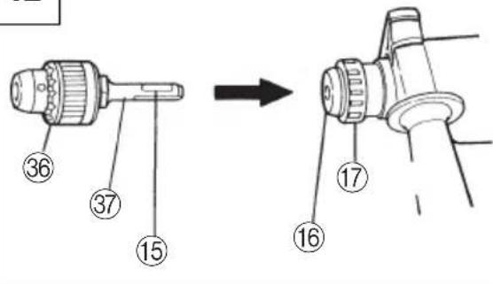
1. Mounting the drill bit (Fig. 6)
(1) To attach a drill bit (SDS-plus shank), fully pull the grip in the direction of the arrow as shown in Fig. 6 and insert the drill bit as far as it will go while rotating.
(2) By releasing the grip, the drill bit will be secured.
(3) To remove the drill bit, fully pull the grip in the direction of the arrow and pull out the drill bit.
2. Confirm that the battery is mounted correctly.
3. Installation of dust cup or dust collector (B) (Optional accessories) (Fig. 8, Fig. 9)
When using a rotary hammer for upward drilling operations attach a dust cup or a dust collector (B) to collect dust or particles for easy operation.
○Installing the dust cup
Use the dust cup by attaching to the drill bit as shown in Fig. 8.
When using a bit which has big diameter, enlarge the center hole of the dust cup with this rotary hammer.
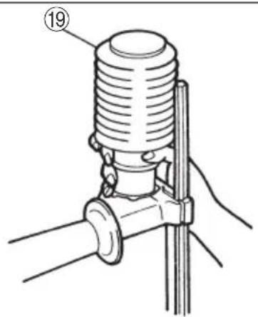
○Installing dust collector (B)
When using dust collector (B), insert dust collector (B) from the tip of the bit by aligning it to the groove on the grip. (Fig. 9)
CAUTION:
○The dust cup and dust collector (B) are for exclusive use of concrete drilling work. Do not use them for wood or metal drilling work.
○Insert dust collector (B) completely into the chuck part of the main unit.
○When turning the rotary hammer on while dust collector (B) is detached from a concrete surface, dust collector (B) will rotate together with the drill
bit. Make sure to turn on the switch after pressing dust cup on the concrete surface. When using dust collector (B) attached to a drill bit that has more than 190 mm of overall length, dust collector (B) cannot touch the concrete surface and will rotate. Therefore, please use dust collector (B) by attaching to drill bits which have 166 mm, 160 mm, and 110 mm overall length.
○Dump particles after every two or three holes when drilling.
○Please replace the drill bit after removing dust collector (B).
4. Selecting the driver bit
Screw heads or bits will be damaged unless a bit appropriate for the screw diameter is employed to drive in the screws.
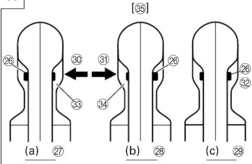
5. Confirm the direction of bit rotation (Fig. 11)
The bit rotates clockwise (viewed from the rear side) by pushing the R-side of the push button. (Fig. 11-a)
The L-side of the push button is pushed to turn the bit counterclockwise. (Fig. 11-b)
The motor does not rotate if the push button is set to the center position. (Fig. 11-c)
6. Continuous drilling
The number of holes that can be drilled in concrete after one recharge is shown in Table 4.
Table 4
| Bit dia. (mm) | Depth (mm) | Possible continuous drilling number (holes) |
| 6.5 30 75 | ||
| 8.5 30 64 | ||
| 12.5 35 42 | ||
| 14.5 45 29 | ||
| 18 40 26 |
These data are for the referential values. The number of holes that can be drilled varies according to the sharpness of the used bit or the conditions of the concrete being drilled.
CAUTION
When using this unit continuously, the unit may overheat, leading to damage in the motor and switch. Please leave it without using it for approximately 15 minutes.
HOW TO USE
1. Switch operation
The rotational speed of the drill bit can be controlled by varying the amount that the trigger switch is pulled. Speed is low when the trigger switch is pulled slightly and increases as the switch is pulled more.
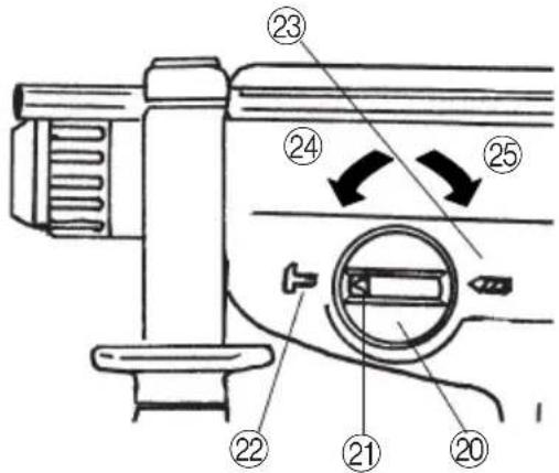
2. Rotation + Striking
Align the “▶” mark with the “T” mark by rotating the change lever to set the “Rotation + Striking” mode. (Fig. 10)
(1) Mount the drill bit.
(2) Pull the trigger switch after applying the drill bit tip to the drilling position. (Fig. 7)
(3) Pushing the rotary hammer forcibly is not necessary at all. Pushing slightly so that drill dust comes out gradually is just sufficient.
CAUTION
When the drill bit touches construction iron bar, the bit will stop immediately and the rotary hammer will react to revolve. Therefore please grip the side handle and handle tightly as shown in Fig. 7.
3. Rotation only
Align the “▶” mark with the “◀” mark by rotating the change lever to set the “Rotation only” mode. (Fig. 10)
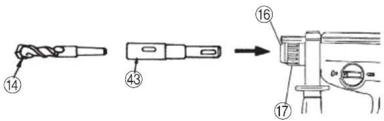
To drill a wood or metal material using the optional drill chuck and chuck adapter, proceed as follows. Installing drill chuck and chuck adapter: (Fig. 12)
(1) Attach the drill chuck to the chuck adaptor.
(2) The part of the SDS-plus shank is the same as the drill bit. Therefore, refer to the item of "Mounting the drill bit" for attaching it.
CAUTIONS
○Application of force more than necessary will not only expedite work at all, but will deteriorate the tip edge of the drill bit and reduce the service life of the rotary hammer in addition.
Drill bit may snap off while withdrawing the rotary hammer from the drilled hole. For withdrawing, it is important to use a pushing motion.
○Do not attempt to use the rotary hammer in the rotation and striking mode with the drill chuck and chuck adapter attached. This would seriously shorten the service life of every component of the machine.
4. When driving wood screws (Fig. 14)
(1) Selecting a suitable driver bit
Employ plus-head screws, if possible, since the driver bit easily slips off the heads of slotted-head screws.
(2) Tightening wood screws
○Prior to tightening wood screws, make pilot holes suitable for them in the wooden board. Apply the bit to the screw head grooves and gently drive the screws in the holes.
CAUTION
Exercise care in preparing a pilot hole suitable for the wood screw taking the hardness of the wood into consideration. Should the hole be excessively small or shallow, requiring much power to drive the screw into it, the thread of the wood screw may sometimes be damaged.
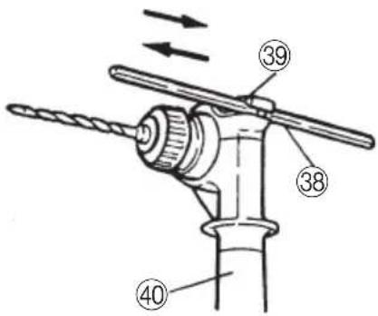
5. Using depth gauge (Fig. 13)
(1) Loosen the knob on the side handle, and insert the depth gauge into the mounting hole on the side handle.
(2) Adjust the depth gauge position according to the depth of the hole and tighten the knob bolt securely.
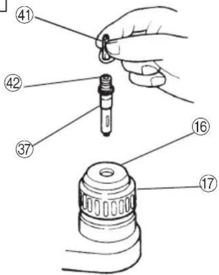
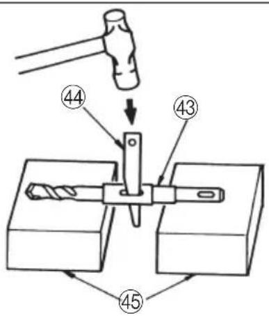
6. How to use the drill bit (taper shank) and the taper shank adapter
(1) Mount the taper shank adapter to the rotary hammer. (Fig. 15)
(2) Mount the drill bit (taper shank) to the taper shank adapter. (Fig. 15)
(3) Turn the switch ON, and drill a hole to prescribed depth.
(4) To remove the drill bit (taper shank), insert the
cotter into the slot of the taper shank adapter and strike the head of the cotter with a hammer supporting on the rest. (Fig. 16)
LUBRICATION
Low viscosity grease is applied to this rotary hammer so that it can be used for a long period without replacing the grease. Please contact the nearest service center for grease replacement when any grease is leaking form loosened screw.
Further use of the rotary hammer despite the grease shortage causes damage to reduce the service life.
CAUTION
A specific grease (FG-6A) is used with this machine, therefore, the normal performance of the machine may be badly affected by use of different grease. Please be sure to let one of our service centers to undertake replacement of the grease.
MAINTENANCE AND INSPECTION
1. Inspecting the tool
Since use of a dull tool will degrade efficiency and cause possible motor malfunction, sharpen or replace the tool as soon as abrasion is noted.
2. Inspecting the mounting screws
Regularly inspect all mounting screws and ensure that they are properly tightened. Should any of the screws be loose, retighten them immediately. Failure to do so could result in serious hazard.
3. Cleaning on the outside
When the power tool is stained, wipe with a soft dry cloth or a cloth moistened with soapy water. Do not use chloric solvents, gasoline or paint thinner, as they melt plastics.
4. Storage
Store the power tool in a place in which the temperature is less than 40^ C and out of reach of children.
5. Service parts list
A: Item No.
B: Code No.
C: No. Used
D: Remarks
CAUTION
Repair, modification and inspection of Hitachi Power Tools must be carried out by an Hitachi Authorized Service Center.
This Parts List will be helpful if presented with the tool to the Hitachi Authorized Service Center when requesting repair or other maintenance.
In the operation and maintenance of power tools, the safety regulations and standards prescribed in each country must be observed.
MODIFICATIONS
Hitachi Power Tools are constantly being improved and modified to incorporate the latest technological advancements.
Accordingly, some parts (i.e. code numbers and/or design) may be changed without prior notice.
NOTE
Due to HITACHI's continuing program of research and development, the specifications herein are subject to change without prior notice.
IMPORTANT
Correct connections of the plug
The wires of the mains lead are coloured in accordance with the following code:
Blue: -Neutral
Brown: -Live
As the colours of the wires in the mains lead of this tool may not correspond with the coloured markings identifying the terminals in your plug proceed as follows: The wire coloured blue must be connected to the terminal marked with the letter N or coloured black.
The wire coloured brown must be connected to the terminal marked with the letter L or coloured red.
Neither core must be connected to the earth terminal. NOTE
This requirement is provided according to BRITISH STANDARD 2769: 1984.
Therefore, the letter code and colour code may not be applicable to other markers except United Kingdom.
Information concerning airborne noise and vibration The measured values were determined according to EN50144.
The typical A-weighted sound pressure level: 92 dB (A)
The typical A-weighted sound power level: 105 dB (A)
Wear ear protection.
The typical weighted root mean square acceleration value: 8.0m/s^2
natural_image
Simple line drawing of a rectangular electronic component with two leads (no text or symbols)natural_image
Line drawing of a mechanical device with handle and control panel (no text or symbols)natural_image
Line drawing of a mechanical device with handle and control panel (no text or symbols)natural_image
Simple line drawing of a rectangular electronic component with a small protrusion at the bottom (no text or symbols)natural_image
Line drawing of a mechanical device with no visible text or symbols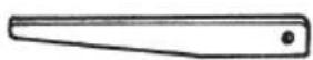
Clavette
natural_image
Line drawing of a mechanical device with handle and lever (no text or symbols)natural_image
Line drawing of a handheld device with handle and control panel (no text or symbols)| Dimension de l'ancrage |
| W1/4" |
| W5/16" |
| W3/8" |
| W1/2" |
| W5/8" |
natural_image
Line drawing of a handheld device with handle, control panel, and zoomed-in circular dial (no text or symbols)natural_image
Simple line drawing of a rectangular electronic component with a small protruding pin (no text or symbols)natural_image
Line drawing of a handheld device with handle and control knob (no text or symbols)natural_image
Line drawing of a mechanical device with handle and control panel (no text or symbols)natural_image
Line drawing of a mechanical device with handle and control panel (no text or symbols)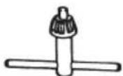
Chiave per mandrino
natural_image
Line drawing of a mechanical device with handle and control panel (no text or symbols)natural_image
Simple line drawing of a rectangular electronic component with a small protrusion at the bottom (no text or symbols)natural_image
Line drawing of a mechanical device with handle and control panel (no text or symbols)natural_image
Line drawing of a mechanical device with handle and control panel (no text or symbols)natural_image
Line drawing of a handheld device with handle and control panel (no text or symbols)| Medida de ancla |
| W1/4" |
| W5/16" |
| W3/8" |
| W1/2" |
| W5/8" |
natural_image
Line drawing of a handheld toilet with handle and control panel (no text or symbols)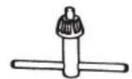
natural_image
Line drawing of a mechanical device with handle and control panel (no text or symbols)natural_image
Simple line drawing of a rectangular electronic component with a small protruding base (no text or symbols)natural_image
Line drawing of a toilet with handle and seat (no text or symbols)
Cavilha
| Diâmetro externo |
| 11,0 mm |
| 12,3 mm |
| 14,3 mm |
| 14,5 mm |
| 17,5 mm |
natural_image
Line drawing of a mechanical device with handle and control panel (no text or symbols)Mandril de 13 mm de martelo perfurador (cabo SDS-plus)
natural_image
Line drawing of a handheld device with handle and control panel (no text or symbols)| Tamanho da âncora |
| W1/4" |
| W5/16" |
| W3/8" |
| W1/2" |
| W5/8" |
natural_image
Line drawing of a toilet with handle and side panel (no text or symbols)natural_image
Simple line drawing of a rectangular electronic component with a small protrusion at the bottom (no text or symbols)natural_image
Line drawing of a mechanical device with handle, seat, and control panel (no text or symbols)
Κόφτης
natural_image
Line drawing of a hand pump assembly with no text or symbolsnatural_image
Line drawing of a mechanical device with handle and control panel (no text or symbols)ΕΦΑΡΜΟΓΕΣ
text_image
Exploded view diagram of a mechanical assembly with numbered parts and labeled components| English | Nederlands | ||
| EC DECLARATION OF CONFORMITYWe declare under our sole responsibility that this product is in conformity with standards or standardized documents EN50144 and EN55014-2 in accordance with Council Directives 89/336/EEC and 98/37/EC.This declaration is applicable to the product affixed CE marking. | EC VERKLARING VAN CONFORMITEITWij verklaren onder eigen verantwoordelijkheid dat dit produkt conform de richtlijnen of gestandardiseerde documenten EN50144 en EN55014-2 voldoet aan de eisen van EEG Bepalingen 89/336/EEG en 98/37/EC.Deze verklaring is van toepassing op produkten voorzien van de CE-markeringen. | ||
| Deutsch | Español | ||
| ERKLÄRUNG ZUR KONFORMITÄT MIT CE-REGELNWir erklären mit alleiniger Verantwortung, daß dieses Produkt den Standards oder standardisierten Dokumenten EN50144 und EN55014-2 in Übereinstimmung mit den Direktiven des Europarats 89/336/EWG und 98/37/CE entspricht.Diese Erklärung gilt für Produkte, die die CE-Markierung tragen. | DECLARACIÓN DE CONFORMIDAD DE LA CEDeclaramos bajo nuestra única responsabilidad que este producto está de acuerdo con las normas o con los documentos de normalización EN50144 y EN55014-2 según indican las Directrices del Consejo 89/336/CEE y 98/37/CE.Esta declaración se aplica a los productos con marcas de la CE. | ||
| Français | Portugües | ||
| DECLARATION DE CONFORMITE CENous déclarons sous notre seule et entière responsabilité que ce produit est conforme aux normes ou documents normalisés EN50144 et EN55014-2 en accord avec les Directives 89/336/CEE et 98/37/CE du Conseil.Cette déclaration s'applique aux produits désignés CE. | DECLARAÇÃO DE CONFORMIDADE CEDeclaramos, sob nossa única e inteira responsabilidade, que este produto está de acordo com as normas ou documentos normativos EN50144 e EN55014-2 em conformidade com as Diretrizes 89/336/CEE e 98/37/CE do Conselho.Esta declaração se aplica aos produtos designados CE. | ||
| Italiano | Ελληνικά | ||
| DICHIARAZIONE DI CONFORMITÀ CESi dichiara sotto nostra responsabilità che questo prodotto è conforme agli standard o ai documenti standardizzati EN50144 e EN55014-2 conforme alle direttive 89/336/CEE e 98/37/CE del concilio.Questa dichiarazione è applicabile ai prodotti cui sono applicati i marchi CE. | ΕΚ ΔΗΛΩΣΗ ΕΝΑΡΜΟΝΙΣΜΟΥΔηλώνουμε με απόλυτη υπευθυνότητα ότι αυτό το προϊόν είναι εναρμονισμένο με τα πρότυπα ή τα έγραφα προτύπων EN50144 και EN55014-2 σε συμφωνία με τις Οδηγίες του Συμβουλίου 89/336/ΕΟΚ και 98/37/ΕΚ.Αυτή η δήλωση ισχύει στο προϊόν με το σημάδι EC. | ||
| Representative office in EuropeHitachi Power Tools Europe GmbHSiemensring 34, 47877 Willich 1, F. R. GermanyHead office in JapanHitachi Koki Co., Ltd.Shinagawa Intercity Tower A, 15-1, Konan 2-chome,Minato-ku, Tokyo, Japan | CE28. 11. 2003K. KatoBoard Director | ||