
Ultima 35 EZload - Laminating machine GBC - Free user manual and instructions
Find the device manual for free Ultima 35 EZload GBC in PDF.
| Product Type | Laminating Machine |
| Brand | GBC |
| Model | Ultima 35 EZload |
| Operating Speed | Variable with automatic mode |
| Warm-up Time | Less than 2 minutes |
| Supported Film Thickness | 38 - 125 microns (1.5 - 5.0 mil) |
| Maximum Film Width | 305 mm |
| Maximum Media Width | 292 mm |
| Media Thickness | 65 - 220 microns |
| Device Dimensions (L x H x D) | 493 × 290 × 427 mm |
| Package Dimensions (L x H x D) | 579 × 381 × 533 mm |
| Net Weight | 18.1 kg |
| Gross Weight | 20.1 kg |
| Auto Shut-off | After 60 minutes of inactivity |
| Fuse | Internal, not user-replaceable |
| Operating Environment | 5 - 35°C, maximum altitude 2,000 m |
| Control Functions | Start, Stop, Reverse buttons, film thickness selector, speed dial, automatic mode, standby |
| Loading System | Removable feed table with safety latch, adjustable stop, protective cover |
| Heating Elements | Teflon-coated heating shoes |
| Safety Devices | Protective cover, feed table latch, auto shut-off, burn protection |
| Routine Maintenance | Clean heating shoes with a damp, lint-free cloth or isopropyl alcohol |
| Spare Parts and Repairability | Film rolls are user-replaceable; any other repair must be handled by customer service |
Frequently Asked Questions - Ultima 35 EZload GBC
User questions about Ultima 35 EZload GBC
0 question about this device. Answer the ones you know or ask your own.
Ask a new question about this device
Download the instructions for your Laminating machine in PDF format for free! Find your manual Ultima 35 EZload - GBC and take your electronic device back in hand. On this page are published all the documents necessary for the use of your device. Ultima 35 EZload by GBC.
USER MANUAL Ultima 35 EZload GBC
natural_image
Exterior view of a black and silver industrial printing press machine (no visible text or symbols)start here
starten sie hier
démarrez ici
iniziare qui
empieza aquí
begin hier
natural_image
Exterior view of a modern office building (no signage)| English5 | |
| Deutsche | 9 |
| Français | 13 |
| Italiano | 17 |
| Español | 21 |
| Nederlands | 25 |
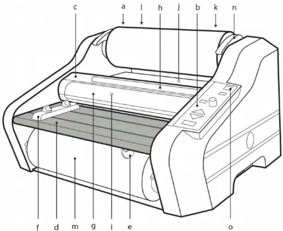
fig. 1
fig. 2
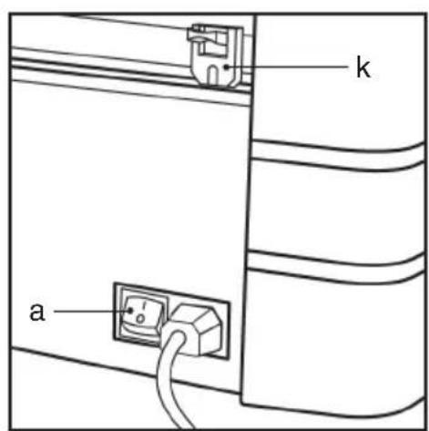
fig. 3
natural_image
Diagram of a car interior showing a curved roof and a hand holding a small object, with no visible text or symbols.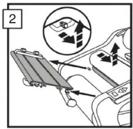
natural_image
Line drawing of a mechanical roller or printer with multiple rollers and adjustment knobs (no text or symbols)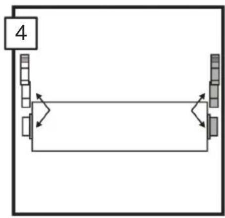
flowchart
graph TD
    A["4"] --> B["Process Step 1"]
    B --> C["Process Step 2"]
    C --> D["Process Step 3"]
    D --> E["End"]
natural_image
Diagram of a printer or scanner with paper roll and scroll, showing motion arrows (no text or symbols)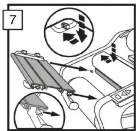
natural_image
Diagram showing a curved panel with layered bands and a black arrow pointing to a small object, labeled '8' in the top-left corner (no text or symbols on the diagram itself)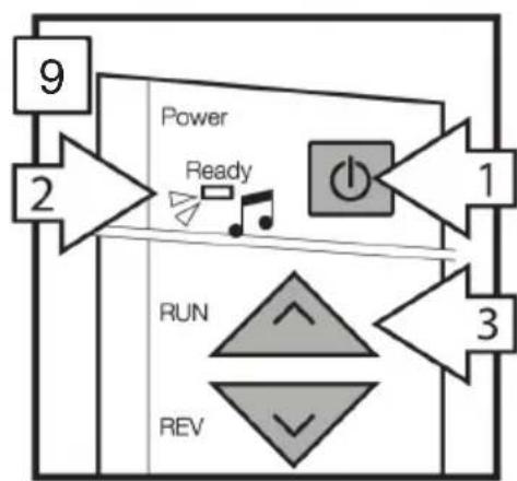
flowchart
graph TD
    A["9"] --> B["2"]
    B --> C["Power"]
    C --> D["Ready"]
    D --> E["1"]
    E --> F["3"]
    F --> G["RUN"]
    G --> H["REV"]
    H --> I["2"]
natural_image
Illustration of a printer with paper and arrows indicating printing process (no text or symbols)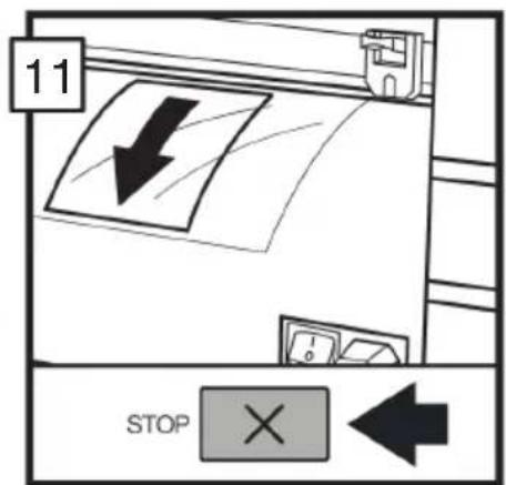
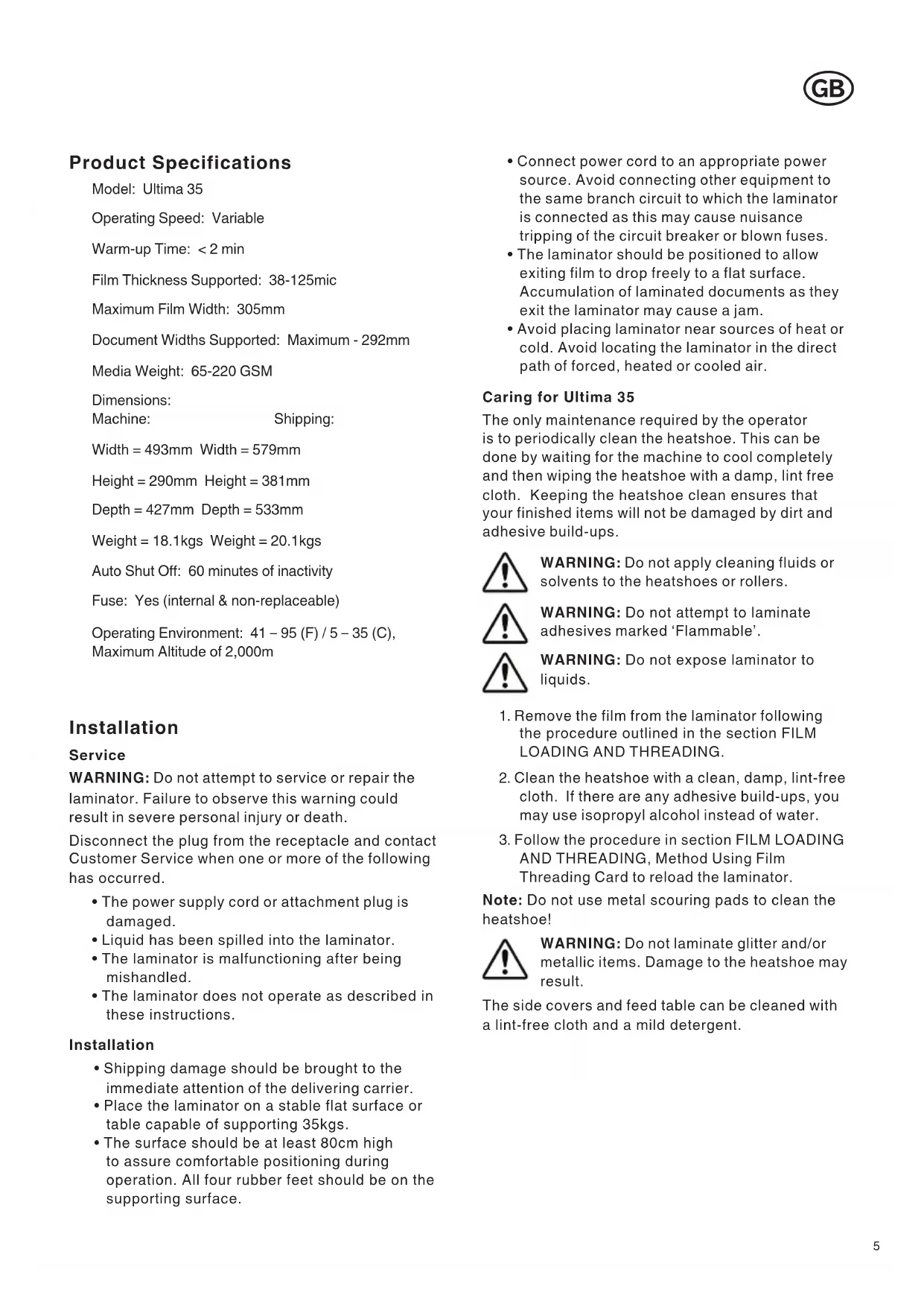
Product Specifications
Model: Ultima 35
Operating Speed: Variable
Warm-up Time: < 2 min
Film Thickness Supported: 38-125mic
Maximum Film Width: 305mm
Document Widths Supported: Maximum - 292mm
Media Weight: 65-220 GSM
Dimensions:
Machine: Shipping:
Width = 493mm Width = 579mm
Height = 290mm Height = 381mm
Depth = 427mm Depth = 533mm
Weight = 18.1 kgs Weight = 20.1 kgs
Auto Shut Off: 60 minutes of inactivity
Fuse: Yes (internal & non-replaceable)
Operating Environment: 41 - 95 (F) / 5 - 35 (C),
Maximum Altitude of 2,000m
Installation
Service
WARNING: Do not attempt to service or repair the laminator. Failure to observe this warning could result in severe personal injury or death.
Disconnect the plug from the receptacle and contact Customer Service when one or more of the following has occurred.
- The power supply cord or attachment plug is damaged.
- Liquid has been spilled into the laminator.
- The laminator is malfunctioning after being mishandled.
- The laminator does not operate as described in these instructions.
Installation
- Shipping damage should be brought to the immediate attention of the delivering carrier.
- Place the laminator on a stable flat surface or table capable of supporting 35kgs.
-
The surface should be at least 80cm high to assure comfortable positioning during operation. All four rubber feet should be on the supporting surface.
-
Connect power cord to an appropriate power source. Avoid connecting other equipment to the same branch circuit to which the laminator is connected as this may cause nuisance tripping of the circuit breaker or blown fuses.
- The laminator should be positioned to allow exiting film to drop freely to a flat surface. Accumulation of laminated documents as they exit the laminator may cause a jam.
- Avoid placing laminator near sources of heat or cold. Avoid locating the laminator in the direct path of forced, heated or cooled air.
Caring for Ultima 35
The only maintenance required by the operator is to periodically clean the heatshoe. This can be done by waiting for the machine to cool completely and then wiping the heatshoe with a damp, lint free cloth. Keeping the heatshoe clean ensures that your finished items will not be damaged by dirt and adhesive build-ups.

WARNING: Do not apply cleaning fluids or solvents to the heatshoes or rollers.

WARNING: Do not attempt to laminate adhesives marked ‘Flammable’.

WARNING: Do not expose laminator to liquids.
- Remove the film from the laminator following the procedure outlined in the section FILM LOADING AND THREADING.
- Clean the heatshoe with a clean, damp, lint-free cloth. If there are any adhesive build-ups, you may use isopropyl alcohol instead of water.
- Follow the procedure in section FILM LOADING AND THREADING, Method Using Film Threading Card to reload the laminator.
Note: Do not use metal scouring pads to clean the heatshoe!

WARNING: Do not laminate glitter and/or metallic items. Damage to the heatshoe may result.
The side covers and feed table can be cleaned with a lint-free cloth and a mild detergent.
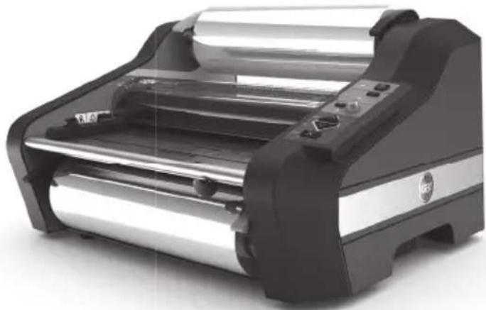
Feature Guide
GETTING TO KNOW YOUR LAMINATOR (FIGURE 1):
a. POWER SWITCH (FIGURE 2):
i.) Located at the back of the machine, applies power to the laminator. The "ON" position is indicated by the "I" symbol. The "OFF" position is indicated by the "O" symbol.
b. CONTROL PANEL (FIGURE 3):
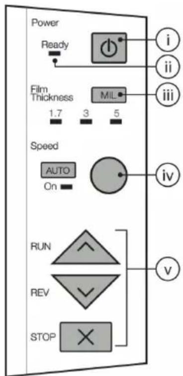
i.) STANDBY BUTTON (☐): Push to turn laminator on or off when main power switch at the rear of machine is in the "ON" (I) position.
ii.) READY LAMP: This will blink until the laminator has reached operating temperature. Once operating temperature is reached, the light will remain on.
iii.) FILM THICKNESS (MIL): Push to indicate film roll thickness. Light will illuminate under selected film type.
iv.) SPEED KNOB & AUTO BUTTON: Knob controls the speed of the rollers. Select "AUTO" to allow machine to run at pre-set speed.
v.) RUN/REV/STOP BUTTONS: Controls the operation of the rollers. Select "RUN" button to start laminating. Select "STOP" when the item has passed through the machine and lamination is complete. Select "REV" to clear mis-feed, jams, or wrap-ups.
c. HEAT SHIELD:
i.) Prevents inadvertent contact with the heat shoes.
d. FEED TABLE:
i.) The Feed Table is used to position items for lamination. The laminator will operate only when the Feed Table and Feed Table Latch are properly secured into place.
e. FEED TABLE LATCH:
i.) Locks the Feed Table into position and activate an interlock switch. The latch is located on the right underside of the Feed Table. The Feed Table can be removed by retracting the latch and lifting the table upward and away from the laminator.
f. FEED TABLE GUIDE:
i.) The Feed Table Guide aligns items to be laminated and is used to ensure that longer items are fed into the laminator straight. The Feed Guide may also be used to feed smaller items side by side. To position the adjustable guide, loosen the knob on the top of the adjustment guide, slide the guide into the desired position, and then tighten the knob by twisting counter clockwise.
g. HEAT SHOES:
i.) Teflon coated heat shoes melt the adhesive on the laminating film before the nip rollers compress it.
h. IDLER BARS:
i.) The Idler Bars, located near each supply roll, are used to direct the film to the heat shoes. The lower Idler Bar is attached to the Feed Table to facilitate easy film loading.
i. NIP ROLLERS:
i.) The Nip Rollers are located behind the heat shoes. The nip point is where the heated film is compressed and pulled through the laminator.
j. PULL ROLLERS:
i.) The Pull Rollers are located at the back of the laminator. They simultaneously pull the film through the laminator and provide tension as the film cools to provide good quality lamination.
k. REAR SLITTER (FIGURE 2):
i.) Used to cut the film where it exits the rear of the laminator.
I. SUPPLY ROLL:
i.) The Film Supply Rolls have core plugs inserted into each end of the rolls. The left and right plugs are different colors and diameters. The color and diameter of the end plugs correspond to the size of the holder and color sticker located on the side plate of the laminator.
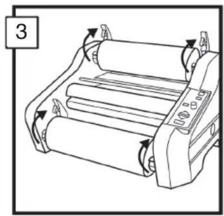
m. FILM HOLDER LEVERS:
i.) There are four film holder levers; two for the top roll and two for the bottom roll. These must be raised to install and remove film rolls. Once installation is complete, close the levers to secure the rolls in place.
Film Loading and Threading
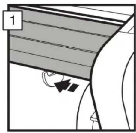
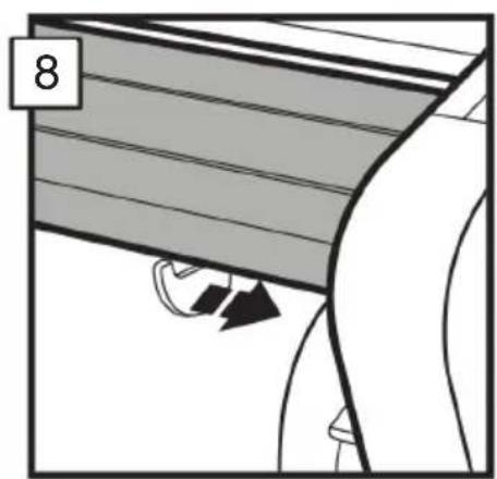
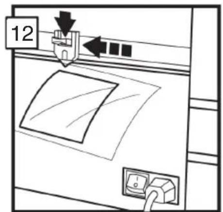
Follow the below procedures to remove the feed table and Heat Shield.
- Slide the feed table latch to the left.
- Remove the heat shield by sliding it to the left or right and lifting it up and away from the laminator. Lift the feed table upwards and away from the laminator.

CAUTION: HEAT SHOES COULD BURN YOU. DO NOT TOUCH.
If reloading film, cut the remaining top and bottom film webs between the supply rolls and heat shoes. Be careful to not scratch the heat shoes. Remove the old rolls and check the heat shoes for adhesive residue. Any residue can be easily removed by wiping the heat shoe with a damp cloth. Do not use anything abrasive, as it will damage the Teflon coating on the heat shoe.
Change the top and bottom supply roll at the same time.
- Raise the four film holder levers and remove old rolls of film.
- Install new film rolls making sure that color and diameter of end pugs correspond to the size of the holder and color sticker located on the side plate of the laminator.
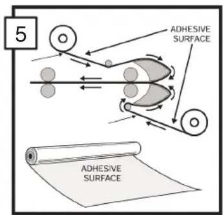
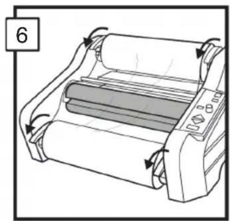
- Refer to the Threading Guide located on the side panel for illustration of properly loaded film. Unwind top and bottom film rolls allowing enough slack for threading. Drape the film from lower supply roll over the heat shoes allowing enough slack to reinstall the feed table/idler bar. Thread film from upper roll under the idler bar and drape over the heat shoes.
- Close the four film holder levers.
- Reinstall feed table and heat shield and slide feed table latch to the right.
- Complete above steps 1-7 while the machine is off and cold. Once complete, turn the machine on and allow it to warm up before proceeding to steps 9 and 11.
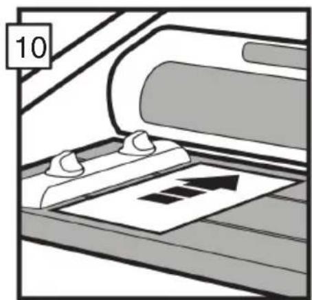
- Press the RUN button. Slide the threading card (provided with new rolls of GBC laminating film) on the feed table, gently pushing the film into the nip rollers. The Threading card should now be guiding both rolls of film through the laminator.
- Press the STOP button when the threading card exists the rear of the laminator.


CAUTION: SHARP BLADE
- The film cutter may be used to separate the laminated items. Position the cutter on either side of the laminator, depress the cutter handle, and slide the cutter across the film.
Operation
CAUTION: MAKE SURE HEAT SHIELD AND FEED TABLE ARE IN THE PROPER POSITION TO OPERATE THE UNIT.
-
Move the main power switch to the "ON" position (FIGURE 2). With the main power switch in the "ON" position, the laminator can be turned on or off using the standby button ( ⏻ ) located on the control panel.
-
Select proper film thickness on the control panel by pressing the "MIL" button until the light under the film thickness is illuminated (FIGURE 3, iii).
-
Reference table printed on the Feed Table to select proper speed based on document thickness, or press "Auto" to allow machine to run at Auto Speed.
-
When the laminator reaches operating temperature, the ready light indicator will illuminate.
-
Position the item(s) to be laminated on the feed table.
-
Push the "RUN" button.
-
Slide the item(s) to be laminated into the nip rollers.
-
When the laminated item(s) exits the rear of the laminator, press the "STOP" button.
-
Use the Rear Slitter located at the back of the laminator to separate the laminated item(s) from the film web.
CLEARING A FILM JAM (WRAP-UP)
Film jams may occur if the laminator is not positioned to allow exiting film to drop freely to the floor. Accumulation of laminate as it exits the laminator may cause film to wrap around the roller, causing a jam.
To clear a jam, it is necessary to rotate the rollers in a reverse direction.
-
Immediately stop the laminator by pushing the "STOP" button.
-
Remove the feed table and heat shield.
-
Cut the top and bottom film webs.
-
Install the feed table with the loose ends of the web on top of the table.
-
Press the "REV" button to run the machine in reverse. Then grasp the loose ends of the web and pull straight out to guide the film out of the laminator.
-
When the film has cleared the heat shoes, press the "STOP" button.
-
Thread the film as indicated in the "FILM LOADING AND THREADING" section of this manual.
HELPFUL LAMINATING TIPS
- Do not attempt to laminate abrasive or metal items such as staples or paper clips as they will damage the heat shoes and rollers.
- Do not force items into the nip area of the rollers. An item that is not easily drawn into the laminator is probably too thick to laminate.
- Wrinkles may result if an attempt is made to reposition an item once the rollers have grasped it.
- Do not stop the laminator before an item has completely exited the rear of the laminator. Even a momentary stop will cause a mark (heat line) to appear on the laminated item.
Avoid adhesive deposits on the heat shoes and rollers by:
- Use both top and bottom rolls of film. Both rolls must be used for problem free lamination.
- Do not allow rolls of film to run completely off the core.
Technische Daten
Modell: Ultima 35
Höhe = 290 mm Höhe = 381 mm
Tiefe = 427 mm Tiefe = 533 mm


- start here
- Product Specifications
- Installation
- Service
- Caring for Ultima 35
- Feature Guide
- GETTING TO KNOW YOUR LAMINATOR (FIGURE 1):
- a. POWER SWITCH (FIGURE 2):
- b. CONTROL PANEL (FIGURE 3):
- c. HEAT SHIELD:
- d. FEED TABLE:
- e. FEED TABLE LATCH:
- f. FEED TABLE GUIDE:
- g. HEAT SHOES:
- h. IDLER BARS:
- i. NIP ROLLERS:
- j. PULL ROLLERS:
- k. REAR SLITTER (FIGURE 2):
- SUPPLY ROLL:
- m. FILM HOLDER LEVERS:
- Film Loading and Threading
- CAUTION: HEAT SHOES COULD BURN YOU. DO NOT TOUCH.
- CAUTION: SHARP BLADE
- Operation
- CAUTION: MAKE SURE HEAT SHIELD AND FEED TABLE ARE IN THE PROPER POSITION TO OPERATE THE UNIT.
- CLEARING A FILM JAM (WRAP-UP)
- HELPFUL LAMINATING TIPS
- Avoid adhesive deposits on the heat shoes and rollers by:
- Technische Daten
Brand : GBC
Model : Ultima 35 EZload
Category : Laminating machine