
Pinnacle 27 - Laminating machine GBC - Free user manual and instructions
Find the device manual for free Pinnacle 27 GBC in PDF.

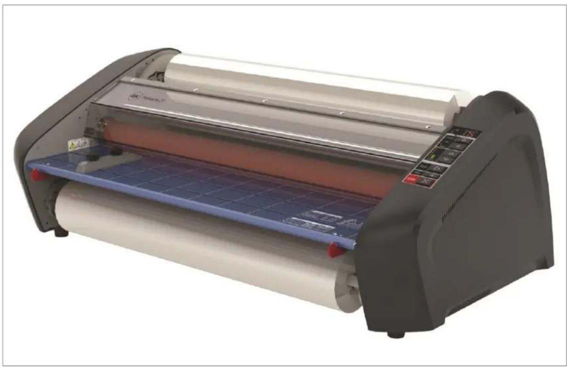
| Product Type | Hot Laminating Machine |
| Brand | GBC |
| Model | Pinnacle 27 |
| Machine Dimensions (W x H x D) | 90.1 x 32.4 x 49.5 cm |
| Machine Weight | 50.3 kg |
| Package Dimensions (W x H x D) | 104.8 x 45.7 x 66.7 cm |
| Package Weight | 52.6 kg |
| Power Supply | 120 V, 60 Hz, NEMA 5-15R plug |
| Maximum Film Width | 68.6 cm (27 in) |
| Maximum Roll Diameter | 12.7 cm (4.25 in) |
| Supported Roll Types | Standard rolls with 2.5 cm (1 in) core |
| Supported Film Thicknesses | Nap I: 1.5 mil / 3 mil (38 / 75 microns); Nap II: 1.5 mil / 3 mil |
| Laminating Speed | Variable: 0.6 to 3.0 m/min (2 to 10 ft/min) |
| Preheating Time | Less than 10 minutes |
| Maximum Ambient Temperature | 28 °C (82.4 °F) |
| Main Functions | Heated pressure rollers, feed table, thermal protector, Nap I/II film selector, speed adjustment, length counter, on/off, slow reverse, rear knife, auto shut-off |
| Maintenance and Cleaning | Clean rollers with a damp lint-free cloth; use isopropyl alcohol if necessary. Do not use metal pads. |
| Safety | Thermal protection and feed table lock; hot surface (rollers >260 °F); moving parts; sharp blade; do not open; unplug before maintenance; indoor use only |
| Spare Parts and Repairability | No user-serviceable parts; contact GBC authorized service for repairs; limited 1-year warranty |
| General Information | Light commercial use; auto shut-off after 2 h (standby) then 3 h (power off) |
Frequently Asked Questions - Pinnacle 27 GBC
User questions about Pinnacle 27 GBC
0 question about this device. Answer the ones you know or ask your own.
Ask a new question about this device
Download the instructions for your Laminating machine in PDF format for free! Find your manual Pinnacle 27 - GBC and take your electronic device back in hand. On this page are published all the documents necessary for the use of your device. Pinnacle 27 by GBC.
USER MANUAL Pinnacle 27 GBC
Pinnacle 27/27 EZload
Laminator
Do not duplicate without written permission from ACCO Brands
natural_image
Exterior view of a modern office building (no signage)ACCO Brands reserves the right to make changes to this publication and to the products described in it without noce. All specifications and information concerning products are subject to change without noce. Reference in this publication to information or products protected by copyright or patent does not convey any license under the rights of ACCO Brands or others assumes no liability arising from infringements of patents or any other rights of third pares.
This publication is copyrighted © 2016 by ACCO Brands. All rights reserved.
1. Safety
YOUR SAFETY, AS WELL AS THE SAFETY OF OTHERS IS IMPORTANT TO GBC. IN THIS INSTRUCTION MANUAL AND ON THE PRODUCT ARE IMPORTANT SAFETY MESSAGES. BEFORE YOU INSTALL OR USE THE MACHINE, READ AND FOLLOW ALL THE SAFETY NOTICES CAREFULLY IN THIS CHAPTER.
Observe all the safety information provided. Observe all safety warnings. Never remove safety warnings or other informaon from the equipment.
Read all of the instructions and save these instrucons for further use.

The safety alert symbol precedes each safety noce in this manual. The symbol indicates a potential personal safety hazard to you or others, as well as cause product damage or property damage.

This safety alert symbol indicates a potenal electrical shock. It warns you not to open the paper cuer and expose yourself to hazardous voltage.
THE FOLLOWING WARNINGS ARE FOUND ON THE ULTIMA 65 LAMINATOR.


This means you can be seariously hurt or killed if you open the product and expose yourself to hazardous voltage.
Do not open. No user servicable parts insides. Refer servicing to qualified service personal.


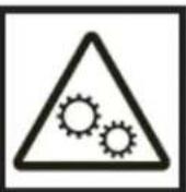

CAUTION Hot Surface: Laminator rollers can be in excess of 260° Fahrenheit. Please use cauon and do not touch the rollers.

Cauon Moving Parts: Laminator rollers are moving parts, please keep body parts away from the rollers as they can be trapped and/or crushed in rollers. Clothing, Jewelry, Long hair and other wearables could be caught in roller path and pull you into the

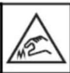

Cauon Sharp Point: The laminator trimmer has a sharp blade. Do not touch the blade poron of the trimmer and use cauon when operang to prevent injury.

WARNING: Do not aempt to service or repair the laminator.

WARNING: do not connect the laminator to an electrical supply or aempt to operate the laminator until you have completely read these instrucons. Maintain these instrucons in a convenient location for future reference.
General safeguards
- Use this laminator only for its intended purposes as according to the specicaons outlined in the operang instrucons.
- Keep hands, long hair, loose clothing and arcs such as necklaces or es away from the front of the rollers to avoid entanglement and entrapment.
-
Avoid contact with the rollers during operaon or shortly aer the laminator has been turned o. The rollers can reach temperatures in excess of 300°F.
-
Keep hands and ngers away from the path of the sharp lm cuer blade located at the lm exit.
- Do not place the laminator on an unstable cart, stand or table. An unstable surface may cause the laminator to fall resulting in serious bodily injury. Avoid quick stops, excessive force and uneven oor surfaces when moving the laminator on a cart or stand.
- Do not defeat or remove electrical and mechanical safety equipment such as interlocks, shields and guards.
- Do not insert objects unsuitable for laminaon.
- Do not expose laminator to liquids.
Electrical Safeguards
- The equipment should be connected to an easily accessible and grounded (3-pin) receptacle (socket outlet) near the equipment.
- This laminator must be connected to a supply voltage corresponding to the electrical range as indicated on the serial plate located on the rear of the machine.
- Unplug the laminator before moving it, or when it is not in use for an extended period of me.
- Do not operate the laminator with a damaged power supply cord or plug.
- Do not overload electrical outlets as this can result in re or shock.
- Do not alter the aachment plug. This plug is congured for the appropriate electrical supply.
- The unit is intended for indoor use only.

CAUTION: The receptacle must be ted near the equipment and easily essible. Do not use an extension cord.
- Disconnect the aachment plug from the receptacle to which it is connected and keep the power supply cord in your possession while moving the laminator.
- Do not operate the laminator with a damaged power supply cord or aachment plug, upon occurrence of a malfuncon, or aer laminator has been damaged. Contact an authorized GBC service representative for assistance.
This equipment is not suitable for use in locaons where children are likely to be
GBC Technical Service
To order replacement accessories, service, parts, or an Equipment Maintenance Agreement, please contact GBC Technical Service and Support at:
United States
ACCO Brands GBC Technical Service and Support 4 Corporate Drive Lake Zurich, IL 60047-8997
1-800-723-4000
www.gbccconnect.com
Canada
Ontario and Quebec – 1-800-268-3310
All other Provinces - 1-800-268-3447
Local 905-595-3100
Callcentre@GBCCanada.com
Mexico
No. 6 corredor industrial
Toluca Lerma, Lerma, México
C.P. 52004 R.F.C. AME640229-1W3
Limited 1 Year Labor Warranty; USA, Mexico, and Canada
ACCO Brands USA LLC, ACCO Brands, 4 Corporate Drive, Lake Zurich, IL 60047 (in Mexico, ACCO Brands Mexicana, Neptuno 43, Fraccionamiento Nueva Industrial Vallejo México 07700 D.F. México), (in Canada, ACCO Brands Canada Inc., 7381 Bramalea Road, Mississauga ON L5S1C4) (each, respectively, "ACCO Brands") warrants to the original purchaser that this ACCO Brands product is free from defects in workmanship and material under normal use and service for a period of: one (1) year for parts and labor aer purchase.
ACCO Brands' obligaon under this warranty is limited to replacement or repair, at ACCO Brands' opon, of any warranted part found defective by ACCO Brands without charge for material or labor. Any replacement, at ACCO Brands' opon, may be the same product or a substanally similar product that may contain remanufactured or refurbished parts. This warranty shall be void in the following circumstances:
(i) if the product has been improperly installed or misused,
(ii) if the product has been damaged by negligence or accident, or
(iii) if the product has been altered by anyone other than ACCO Brands or ACCO Brands' authorized agents.
Without liming the generality of the previous paragraph, ACCO Brands' obligaon under this limited warranty does not include:
(iii) damage caused to the rollers by knives, razors, or other sharp tools; by any foreign objects falling into the working area of the laminator; or by cleaning the laminator with soluons or materials that harm its surfaces;
For warranty execuon, please contact ACCO Brands at: 800-723-4000 or www.gbccconnect.com in the USA 905-595-3100 or www.gbccanada.com in Canada (55) 52.72.2265.65.01 or www.accomexico.com in Mexico
TO THE EXTENT ALLOWED BY APPLICABLE LAW, THIS WARRANTY IS IN LIEU OF ALL OTHER EXPRESSED WARRANTIES. REPRESENTATIONS OR PROMISES INCONSISTENT WITH OR IN ADDITION TO THIS WARRANTY ARE UNAUTHORIZED AND SHALL NOT BE BINDING ON ACCO BRANDS. TO THE EXTENT PERMITTED BY APPLICABLE LAWS, ANY IMPLIED WARRANTIES (IF APPLICABLE) ARE LIMITED IN DURATION TO THE DURATION OF THIS WARRANTY. SOME STATES AND JURISDICTIONS DO NOT ALLOW LIMITATIONS ON HOW LONG AN IMPLIED WARRANTY LASTS, SO THE ABOVE LIMITATION MAY NOT APPLY TO YOU. TO THE EXTENT PERMITTED BY APPLICABLE LAW, IN NO EVENT SHALL ACCO BRANDS BELIABLE FOR ANY SPECIAL, INCIDENTAL, PUNITIVE, EXEMPLARY, CONSEQUENTIAL OR SIMILAR DAMAGES, WHETHER OR NOT FORESEEABLE. SOME STATES AND JURISDICTIONS DO NOT ALLOW THE EXCLUSION OR LIMITATION OF SPECIAL, INCIDENTAL, PUNITIVE, EXEMPLARY, CONSEQUENTIAL, OR SIMILAR DAMAGES, SO THE ABOVE EXCLUSION OR LIMITATION MAY NOT APPLY TO YOU.
FOR CONSUMERS WHO HAVE THE BENEFIT OF CONSUMER PROTECTION LAWS OR REGULATIONS IN THEIR JURISDICTION OF PURCHASE OR, IF DIFFERENT, IN THEIR JURISDICTION OF RESIDENCE, THE BENEFITS CONFERRED BY THIS WARRANTY ARE IN ADDITION TO ALL RIGHTS AND REMEDIES CONVEYED BY SUCH CONSUMER PROTECTION LAWS AND REGULATIONS.
To the extent permied by law, this warranty is not transferable and will automatically terminate if the original product purchaser sells or otherwise disposes of the product.
This warranty gives you specific legal rights. Other rights, which vary from jurisdicon to jurisdicon, may exist. In addition some jurisdicons do not allow (i) the exclusion of certain warranes, (ii) limitaons on how long an implied warranty lasts and/or (iii) the exclusion or limitaon of certain types of costs and/or damages, so the above limitaons may not apply.
3. Specicaons –
| Model | Pinnacle 27 | Pinnacle 27EZ | ||
| Operang Speed | Variable | Variable | ||
| Speed 1 - 10 | 2 ~ 10 ./min. | 2 ~ 10 ./min. | ||
| Warm-up Time | < 10 Minutes | < 10 Minutes | ||
| Maximum Film Width | 27" | 27" | ||
| Maximum Film Roll Diameter | 4.25" | 4.25" | ||
| Film Supplies Supported:• Film Thickness• EZ Load Films• Standard 1" Core Films | Nap I Films• 1.5mil / 3mil (38mic / 75mic)• No• Yes | Nap I Films• 1.5mil / 3mil (38mic / 75mic)• Yes• No | ||
| Dimensions:• Width• Height• Depth• Weight | Machine: Shipping:35.5" (90.1cm) 41.25" (104.8cm)12.75" (32.4cm) 18.00" (45.7cm)19.5" (49.5cm) 26.25" (66.7cm)111lbs (50.3kgs) 116 lbs. (52.6kgs) | Machine: Shipping:35.5" (90.1cm) 41.25" (104.8cm)12.75" (32.4cm) 18.00" (45.7cm)19.5" (49.5cm) 26.25" (66.7cm)111lbs (50.3kgs) 16 lbs. (52.6kgs) | ||
| Electrical Requirements• Voltage• ReceptacleEnvironment | Electrical Requirements• 120V, 60Hz• NEMA 5-15RMaximum Ambient: 82.4°F (28°C) | Electrical Requirements• 120V, 60Hz• NEMA 5-15RMaximum Ambient: 82.4°F (28°C) | ||
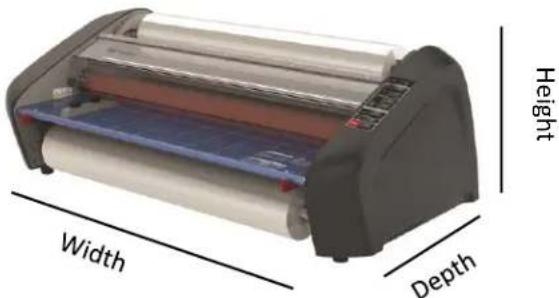
Figure 1: Pinnacle 27/27EZ Dimensions
FCC Class B Notice
This device complies with Part 15 of the FCC Rules. Operation is subject to the following two conditions:
- This device may not cause harmful interference.
- This device must accept any interference received, including interference that may cause undesired operation.
NOTE: This equipment has been tested and found to comply with the limits for a Class B digital device, pursuant to Part 15 of the FCC Rules. These limits are designed to provide reasonable protection against harmful interference in a residential installation. This equipment generates, uses, and can radiate radio frequency energy and, if not installed and used in accordance with the instructions, may cause harmful interference to radio communications. However, there is no guarantee that interference will not occur in a particular installation. If this equipment does cause harmful interference to radio or television reception, which can be determined by turning the equipment off and on, the user is encouraged to try to correct the interference by one or more of the following measures:
- Reorient or relocate the receiving antenna.
- Increase the separation between the equipment and receiver.
- Connect the equipment into an outlet on a circuit different from that to which the receiver is connected.
- Consult the dealer or an experienced radio/TV technician for help.
Canada Class B Noce - Avis
Canada, Class B
This Class B digital apparatus complies with Canadian ICES-003.
Modicaons
Any modicaons made to this device that are not approved by ACCO Brands may void the authority granted to the user by the FCC and/or by Industry Canada to operate this equipment.
4. Installaon
Service

WARNING: Do not aempt to service or repair the laminator. Failure to observe this warning could result in severe personal injury or death.
Disconnect the plug from the receptacle and contact GBC Technical Service when one or more of the following has occurred.
- The power supply cord or aachment plug is damaged.
• Liquid has been spilled into the laminator. - The laminator is m alfunctioning aer being mishandled.
- The laminator does not operate as described in these instructions.
Installaon
- Shipping damage should be brought to the immediate aenon of the delivering carrier.
- Place the laminator on a stable at surface capable of supporting 150 lbs.
- The surface should be at least 30" high to assure comfortable poisoning during operaon. All four rubber feet should be on the supporting surface.
- Connect power cord to an appropriate power source. Avoid connecng other equipment to the same branch circuit to which the laminator is connected as this may cause nuisance tripping of the circuit breaker or blown fuses.
- The laminator should be posioned to allow exing lm to drop freely to the oor. Accumulaon of laminate as it exits the laminator may cause lm to wrap around the rollers, causing a jammed condion.
- Avoid placing laminator near sources of heat or cold. Avoid locang the laminator in the direct path of forced, heated or cooled air.
Caring for Pinnacle 27/27EZload
The only maintenance required by the operator is to periodically clean the rollers. Keeping the rollers clean ensures that your nished items will not be damaged by dirt and adhesive build-ups.

CAUTION: the following procedure is performed while the laminator is hot. Use extreme cauon.

WARNING: Do not apply cleaning uids or solvents to the rollers.

WARNING: Do not aempt to laminate adhesives marked 'Flammable'.

WARNING: Do not expose laminator to liquids.
- Remove the lm from the laminator following the procedure outlined in the secon FILM LOADING AND THREADING.
- Clean the top and boom rollers with a clean, damp lint-free cloth. If there are any adhesive build-ups, you may use isopropyl alcohol instead of water.
- To remove dicult debris Preheat the laminator unl the READY LAMP (Green Light) illuminates.
- Push and hold the SLOW Backward buon to rotate the upper and lower rollers with the safety shield open.
- Follow the procedure in secon FILM LOADING AND THREADING, Method Using Film Threading Card to reload the laminator.
Note: Do not use metal scouring pads to clean the heat rollers!
Note: Covering machine when not in use will reduce dust build-up on the rollers and lm which can lead to poor laminaon quality.

WARNING: Do not laminate glier and/or metallic items. Damage to the rollers may result.
The side covers and feed table can be cleaned with a lint-free cloth and a mild detergent.
5. Feature Guide
natural_image
Line drawing of a handheld electronic device with two circular buttons and a display (no text or symbols)Figure 2
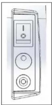
A. MAIN POWER SWITCH: Located at the back of the machine, applies power to the laminator. The 'ON' posion is indicated by the 'I' symbol. The 'OFF' posion marked 'O' symbol (gure 2).
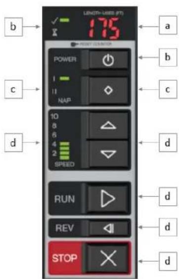
Figure 3
B. CONTROL PANEL:
a. FOOTAGE COUNTER – Tracks the number of feet used since last reset. To reset the footage counter press the RESET buon.
b. ON/OFF BUTTON – Turns the machine ON/OFF and wake the machine up form standby mode.
i. READY – Machine is ready to use when machine beeps and the LED turns GREEN.
ii. WARM-UP – Machine is warming up when the LED is AMBER and blinking.
c. FILM SELECTION – (NAP I or II) – Press the Im selecon buon to toggle between NAP I and NAP II Ims.
d. SPEED CONTROL – Controls the speed of the laminator when the run buon is pushed.
i. MANUAL SETTINGS 1 THRU 10 – Operator can manually select the speed 1 – 10 by pressing the up or down arrows. The speed will increase as you adjust from 1 to 10.
e. RUN – Push the RUN buon to run the laminator in the forward direcon.
f. SLOW REVERSE – Press and Hold to run the machine slowly in Reverse. Using SLOW Speed will allow the machine to run even when Heat Shield is open.
g. STOP – Used to stop the laminator.
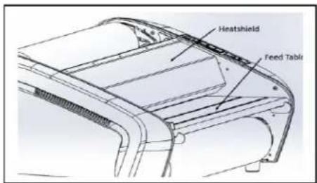
Figure 4
C. HEAT SHIELD: (gure 4) Prevents inadvertent contact with the heat rollers. The HEAT SHIELD must be lowered for the RUN operaon to work.
D. FEED TABLE: (gure 4) The Feed Table is used to posion items for laminaon. Feed table must be installed and latched for laminator to operate.
natural_image
Technical line drawing of a mechanical component with no visible text or symbolsFigure 5
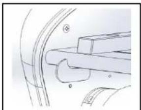
E. FEED TABLE LATCHES: (gure 5) Used to unlock and lock the FEED TABLE.
F. FEED TABLE GUIDE: (gure 5) Aligns items as they are being fed into the laminator. Especially helpful on longer items to reduce skew. The guide can be moved by loosening the knob and sliding the guide
to the desired posion and then ghtening the knob.
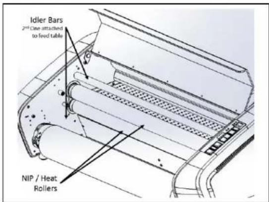
Figure 6
G. HEATED NIP ROLLERS: (gure 6) Heats the lm to acvate the adhesive and provides pressure to ensure lm adheres to the media.
H. IDLER BARS: (gure 6) The Idler Bars, located near each supply roll, are used to direct the lm to the NIP ROLLERS. The lower Idler Bar is aached to the Feed Table to facilitate easy lm loading.
I. PULL ROLLERS: The Pull Rollers are located at the back of the laminator. They simultaneously pull the lm through the laminator and provide tension as the lm cools to ensure quality laminaon.
natural_image
Pure mechanical assembly diagram without any text, numbers, or symbolsFigure 7
J. REAR SLITTER: (gure 7) Used to cut the lm when it exits the rear of the laminator.
K. Circuit Breaker: (gure 2) The circuit breaker is located below the power cord and can be reset by pushing the buon. If the circuit connues to fail, please contact authorized service provider.
L. AUTO SHUT-OFF: Aer two hours of inactivity the laminator will go into Standby mode reducing heat and appearing to be shut down. Aer three hours of inactivity the machine will shut down. To acvate the laminator, ensure the Main Power buon is in the ON posion ('1') and press the ON/OFF buon on the front of the machine.
natural_image
Two cylindrical film samples labeled 'EZload Film' and 'Standard Film', showing different material compositions (no text or symbols on the films themselves)Figure 8
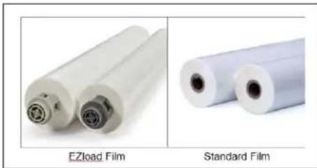
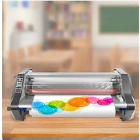
M. FILM ROLL SUPPLY: The Pinnacle 27 uses standard rolls of lm while the Pinnacle 27 EZload uses EZ Load laminang lm (gure 8).
natural_image
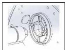
Technical line drawing of a mechanical component with no visible text or symbolsFigure 9
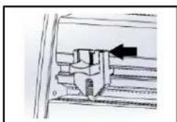
N. FILM SADDLES: EZLoad lm supply is loaded into the saddles on the Pinnacle 27EZload (gure 9).
natural_image
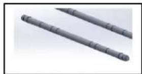
Two gray cylindrical objects with evenly spaced ridges, resembling stylized sticks or rods (no text or symbols visible)Figure 10
O. AutoGrip FILM SHAFT: The Film Sha is used for loading standard lm onto the Pinnacle 27 Laminator. (Figure 10)
natural_image
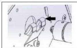
Mechanical assembly diagram showing a tool interacting with a component (no text or symbols visible)Figure 11
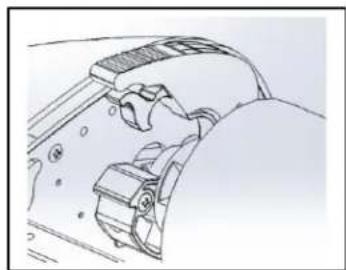
P. FILM BRACKET AND HOLDER: Film sha is loaded into the holder (gure 10a) and bracket (gure 11b).
7. Operaon
FILM LOADING
natural_image
Two-panel image showing a car tire rolling down and a hand holding a blue plastic roller over a black surface (no text or symbols visible)Figure 12
natural_image
Two-panel image showing a hand holding a pen over a metallic panel and a mechanical device with a handle (no visible text or symbols)Figure 13

natural_image
Two-panel image showing a person handling a large paper roll on an industrial machine, and another person handling a red roller on a flat sheet (no visible text or symbols)Figure 14
natural_image
Two-panel image showing a hand operating a large roller with red liquid, next to a second roller filled with white paper (no text or symbols visible)Figure 15
natural_image
Two photos showing a person handling a blue plastic roller on a car (left) and a person seated in a vehicle (right), both without visible text or symbols.Figure 16
flowchart
graph TD
    A["②"] --> B["①"]
    B --> C["●"]
    C --> D["●"]
    D --> E["●"]
Figure 17

CAUTION: the following procedure is performed while the laminator is hot. Use extreme cauon.
TIP: Film loading is easiest when machine is in a Ready State or while warming up.
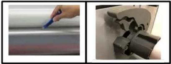
Step 1: Li Safety Shield and remove the feed table by pressing inwards on the table latches and liing up and out. (Fig. 12)
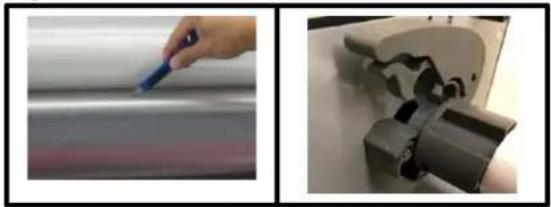
Step 2: If reloading lm, cut the remaining top and boom lm webs between the supply rolls and the idler bars (Fig 13)
Pinnacle 27 EZLoad - Film Loading
Step 3: Pinnacle EZload Raise the four lm levers on the FILM SADDLES and remove the old rolls of lm. (Fig. 13)
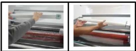
Step 4: Install new Im rolls (Fig 14a)
a. EZLoad Film – Insert the lm directly into the lm saddles, making sure the lm end plugs correspond with the saddles in color and size.
Step 5: Close the four lm holder levers on the saddles. And go to step 6 below.
Pinnacle 27 - Standard Film Loading
Step 3: Remove old rolls of lm (Fig. 14b)
a. Remove Autogrip shas from machine by liing up from the lm bracket and lightly pulling out of lm holder
b. Slide empty lm roll o the sha away from black O-ring.
Step 4: Install new lm rolls on lm sha (Fig 14b)
a. Ensure O-ring on sha is set in the proper grove based on lm width.
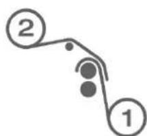
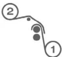
b. Slide the roll of lm on the sha, ensuring lm is in proper orientaon. Reference Figure 17 for top and boom roll.
Step 5: Re-Install Im sha by rst inserng the black hex end of sha into the Hex Sha Holder and lowering the other end into the Film sha bracket.
Both Models connued
Step 6: Thread the Im (Reference Fig. 17)
a. Unwind top and boom lm rolls allowing enough slack for threading.
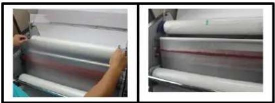
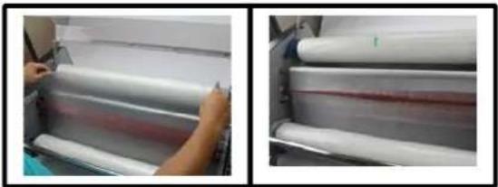
b. Drape Lower supply roll (Role 1) over the top idler bar allowing enough slack to close the feed table. (Fig 15a)
c. Drape the Im from Upper roll (2) over the Im from the lower roll. (Fig 15b)
d. Ensure top and boom lm edges are aligned.
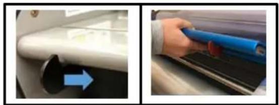
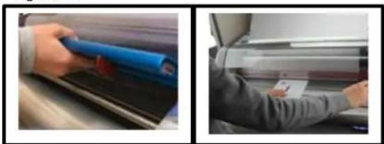
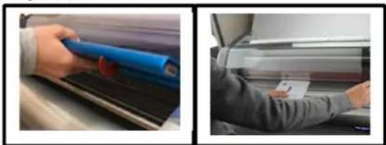
Step 7: Replace the feed table and close the Heat Shield. Turn the top roll of lm an extra 14 turn to create slack in the lm o the top roll. (Fig 16a)
Step 8: Using the Im threading card included with the Im, push the Im into the NIP of the Heat Rollers. Connue to push the threading card while the Forward buon is hit in step 9. (Fig 16b)
Step 9:
Using the RUN buon, push unl rollers start moving while watching the lm thread through the Heat & Pull rollers and observe the lm exing the back of the laminator.
OPERATION
- Move the Main Power switch to the 'ON' () posion (gure 1).
- Ensure the proper lm is selected.
- When the laminator reaches operang temperature, the green ready indicator on the control panel will illuminate.
- Posion the item(s) to be laminated on the feed table.
- Press the RUN buon.
- Slide the item(s) to be laminated into the Heat Rollers.
- When the laminated item(s) exit the rear of the laminator, hit the Stop Buon.
- Use the Rear Slier located at the back of the laminator to separate the laminated item(s) from the lm web.
- During use watch the lm exit to ensure lm is not drawn back into exit to prevent lm wraps.
Note: Connuously feeding similar size media in the same locaon will create a wear spot. Mixing up the feeding locaon will give heat rollers longer life.
CLEARING A JAM
Film jams may occur if the laminator is not posioned to allow exing lm to drop freely to the oor. Accumulaon of laminate as it exits the laminator may cause lm to wrap around the roller, causing a jammed condion.
To clear a jam it is necessary to rotate the rollers in a reverse direcon.
-
Immediately stop the laminator by hing the Stop Buon
-
Open the Heat Shield and remove the Feed Table
- Cut the top and boom lm webs by the Idler bars
- Grasp the loose ends of the lm web and pull straight out while pushing and holding the Reverse Buon.
- When the Im has cleared the Heat Rollers stop the laminator by leng go of the Reverse Buon
- Re-thread the lm following the FILM LOADING instrucons earlier
Laminaon Speed Guide
| Media Type | Speed | |
| Nap I | Nap II | |
| Thin (News Print) | 4 – 5 | 4 – 5 |
| Medium (Copy Paper) | 3 – 5 | 3 – 5 |
| Thick (Card Stock) | 2 – 3 | 2 – 3 |
| Heavy Stock (Poster Board) | 1 - 2 | 1 - 2 |
Laminaon Tips
- Do not aempt to laminate abrasive or metal items such as staples or paper clips as they will damage the heat rollers.
- Do not force items into the nip area of the rollers. An item that is not easily drawn into the laminator is probably too thick to laminate.
- Wrinkles may result if an aempt is made to reposion an item once the rollers have grasped it.
- Do not stop the laminator before an item has completely exited the rear of the laminator. Even a momentary stop will cause a mark (heat line) to appear on the laminated item.
-
Adhesive will be deposited on the Heat Rollers if:
-
Only one roll of lm is used. The top and boom rolls must be used for problem free laminaon.
- One or both rolls of lm are allowed to run completely o the core.
- Top and boom roll lm edges are not evenly aligned
| TROUBLE SHOOTING | ||
| SYMPTON | POSSIBLE CAUSE | CORRECTIVE ACTION |
| Machine will not turn ON | The Main Power switch on the back is not in the ‘ON’ (1) posion.Laminator is not connected to power sourceThe Fuse has been blown | Move the main power switch to the ‘ON’ (1) posionInsert plug into appropriate receptacleReset the circuit breaker |
| Machine is ON but will not run | Heat Shield or Feed Table are not fully closed or latched to acvate safety switch | Ensure the Heat Shield and Feed table are fully closed. |
| Machine rollers stop/stall while laminang | Media is too thickLook for Im wrap around rollers | If possible use thinner media.If Im is wrapped around roller use procedure outlined in Clearing a Jam. |
| Film Doesn’t Sck to Media | Machine not hot enoughRunning to fastWrong Film SengAdhesives will not sck to select Inks/Toners/Toner Oils/Coangs | Ensure ready light is onTry slower speed sengConrm proper Im thickness selectedIf possible print document on another printer |
| Film or Media appears cloudy, milky or silvering (very small dots typically seen in dark areas) | Machine not hot enoughRunning to fastWrong Film SengAdhesives will not sck to select Inks/Toners/Toner Oils/CoangsMachine can also be too hot | Ensure ready light is onTry slower speed sengConrm proper Im thickness selectedIf possible print document on another printerIf above does not resolve try leng the machine cool |
| Long Ripples appear on the Film and/or Media | Film is too hot when exing the pull rollers on the back of the machine. | Slow down the laminatorCommon on longer laminaon runs. Try shorter runs or stop to let cool when present |
| Waves on one side of the Im or media | The Im is walking during laminaon due to uneven tension | Try swapping the top and boom Im rolls |
| Waves appear outward from the trailing edge of media (Boat Waking) | Will occur on thicker media | Use thinner media when possibleSlowing down will reduce amount of boat waking |
| Appearance of small dimples on media and Im (Orange Peel) | Machine is too hot | Ensure Ready light is onConrm proper Im thickness selectedAllow machine to cool |
| Media and Im have lile square paerns on the output (Checker boarding) | Film is too hot when exing the pull rollers on the back of the machine. | Slow down the laminatorCommon on longer laminaon runs. Try shorter runs or stop to let cool whenpresent |
| Gap/Air Pocket between the edge of the media and the lm (Tenng) | Typically found when thicker media is used | Try running slowerEnsure ready light is on and proper temperature.When possible use thinner media |
| Film has bubbles | Uneven tension across the width of the lmDebris in lm and/or on the media or rollerCut or divot in the heat roller silicone | Swap the top and boom rollsWipe them down with a lint-free clothUse cauon when sling lm for roll changes or jams to prevents cuts into the rollers. |
| Film curls opposite direcons on the edges as it exits the back. | Film supplies not properly matched during manufacturing process | Swap the top and boom rolls |
| Media has curl when laminaon complete | Film rolls have too much tension or drag on them.Film Rolls have dierent amounts of tension | Film rolls should be approximately the same size. Try swapping top and boom rolls to change the tension.EZload 27- Ensure the saddles are fully closed- Clean the saddles with lint-free cloth |
| Wrinkles in lm as the lm enters the Heat Rollers | Not enough tension on lm rolls | EZload 27- Ensure the saddles are fully closed- Clean the saddles with lint-free cloth |
| Excessive Adhesive build up on the Heat Roller edges | The Top and Boom roller are not aligned. | When using standard lm make sure both rolls are pressed up against the lm alignment O-ring on the shas. |
Laminadora Pinnacle 27/27 EZload
natural_image
Exterior view of a modern industrial printing press with transparent casing and blue plastic sheet (no visible text or symbols)ACCO Brands GBC Technical Service and Support
4 Corporate Drive Lake Zurich, IL 60047-8997
1-800-723-4000
www.gbccconnect.com
Canadá
Ontario y Quebec: 1 800 268 3310
natural_image
Line drawing of a handheld electronic device with two circular buttons and a screen (no text or symbols)Figura 2
natural_image
Mechanical assembly diagram showing a bracket and mounting bracket (no text or symbols)Figura 5
natural_image
Technical diagram showing a mechanical assembly with an arrow indicating direction (no text or symbols present)Figura 7
natural_image
Technical line drawing of a mechanical component with no visible text or symbolsFigura 9
natural_image
Two cylindrical mechanical rods with segmented ends, no text or symbols visibleFigura 10
natural_image
Diagram of a mechanical device with a lever and rotating components (no text or symbols)Figura 11
natural_image
Two-panel image showing a car wheel cover and a hand holding a blue tool on a car hood (no text or symbols visible)Figura 12
natural_image
Two-panel image showing a hand holding a pen and a mechanical device with a curved handle (no visible text or symbols)Figura 13

natural_image
Two-panel photo showing hands operating a large paper roll on a machine, no visible text or symbolsFigura 14
natural_image
Two-panel image showing a person handling white plastic rolls on a machine, and a close-up of rolled paper sheets with red bands (no visible text or symbols)Figura 15

natural_image
Two-panel image showing a hand holding a blue roller over a black surface next to a person in a suit (no visible text or symbols)Figura 16

flowchart
graph TD
    A["②"] --> B["①"]
    B --> C["●"]
    C --> D["●"]
    D --> E["●"]
Figura 17

natural_image
Exterior view of a modern industrial printing or paper-cutting machine with transparent casing and blue slatted base (no visible text or symbols)

Service technique de GBC
ACCO Brands GBC Technical Service and Support 4 Corporate Drive Lake Zurich, IL 60047-8997 1-800-723-4000 www.gbccconnect.com
Canada
No. 6 corredor industrial
Toluca Lerma, Lerma, México
C.P. 52004 R.F.C. AME640229-1W3
natural_image
Line drawing of a mobile phone control panel with two buttons and a display (no text or symbols)Figure 2
natural_image
Mechanical assembly diagram showing a lever and handle mechanism (no text or labels)Figure 5
natural_image
Technical diagram of a mechanical assembly with an arrow indicating direction (no text or symbols present)Figure 7
natural_image
Technical line drawing of a mechanical component with no visible text or symbolsFigure 9
natural_image
Two gray cylindrical objects with evenly spaced ridges, resembling mechanical rods or tools (no text or symbols visible)Figure 10
natural_image
Diagram of a mechanical device with a black arrow pointing to a component (no text or symbols present)Figure 11
natural_image
Two-panel image showing a car wheel cover and a hand holding a blue tool on a car hood (no text or symbols visible)Figure 12

natural_image
Two-panel image showing a hand holding a pen and a mechanical device with a curved handle (no visible text or symbols)Figure 13
natural_image
Two-panel photo showing hands operating a large paper roll on a machine, no visible text or symbolsFigure 14

natural_image
Two-panel image showing a person handling white plastic rolls on a machine, and a close-up of rolled paper sheets with red bands (no visible text or symbols)Figure 15
natural_image
Two-panel image showing a hand holding a blue roller over a black surface next to a person in a car (no visible text or symbols)Figure 16
flowchart
graph TD
    A["②"] --> B["①"]
    B --> C["●"]
    C --> D["●"]
    D --> E["●"]
Figure 17


- Pinnacle 27/27 EZload
- Laminator
- Safety
- General safeguards
- Electrical Safeguards
- GBC Technical Service
- United States
- Canada
- Mexico
- Limited 1 Year Labor Warranty; USA, Mexico, and Canada
- Specicaons –
- FCC Class B Notice
- Canada Class B Noce - Avis
- Canada, Class B
- Modicaons
- Installaon
- Service
- Installaon
- Caring for Pinnacle 27/27EZload
- Feature Guide
- Operaon
- Pinnacle 27 EZLoad - Film Loading
- Pinnacle 27 - Standard Film Loading
- Both Models connued
- Step 9:
- OPERATION
- CLEARING A JAM
- Laminaon Tips
- Laminadora Pinnacle 27/27 EZload
- Canadá
- Service technique de GBC
Brand : GBC
Model : Pinnacle 27
Category : Laminating machine