CMOS130 - Rear Camera KENWOOD - Free user manual and instructions
Find the device manual for free CMOS130 KENWOOD in PDF.
| Product Type | Rear view camera |
| Brand | Kenwood |
| Model | CMOS130 |
| Sensor | Color CMOS 1/4" |
| Number of pixels | Approximately 380,000 pixels |
| Lens | Wide angle, focal length f=1.12 mm, F value 2.2 |
| Horizontal viewing angle | Approximately 129° |
| Vertical viewing angle | Approximately 104° |
| Video output | 1 Vp-p / 75 Ω |
| Illumination value | 0.9 to 100,000 lux |
| Iris system | Electronic |
| Scanning system | Interlaced |
| Synchronization | Internal |
| Dimensions (L × H × D) | 23.4 × 23.4 × 23.9 mm |
| Weight | Approximately 21 g (without cable) |
| Operating voltage | 14.4 V DC (9.0 V - 16.0 V) |
| Max current consumption | 60 mA |
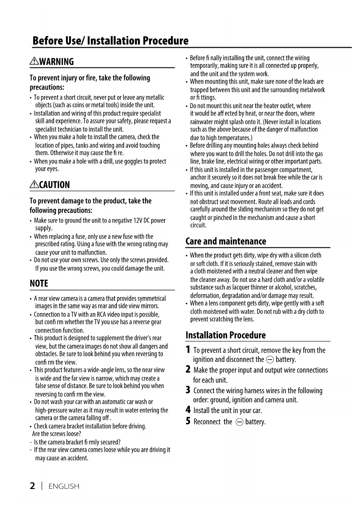
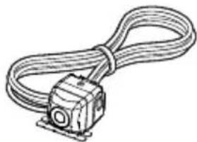
| Supplied accessories | Camera with bracket, fuse, washer, tightening screws |
| Maintenance | Clean with a soft dry or slightly damp cloth; do not use alcohol or solvent |
| Safety | Disconnect the battery before installation; use only the supplied screws; do not expose to rain or high-pressure washing |
| Environmental information | Disposal via selective collection (crossed-out bin pictogram) |
Frequently Asked Questions - CMOS130 KENWOOD
User questions about CMOS130 KENWOOD
0 question about this device. Answer the ones you know or ask your own.
Ask a new question about this device
Download the instructions for your Rear Camera in PDF format for free! Find your manual CMOS130 - KENWOOD and take your electronic device back in hand. On this page are published all the documents necessary for the use of your device. CMOS130 by KENWOOD.
USER MANUAL CMOS130 KENWOOD
To prevent injury or fire, take the following precautions:
- To prevent a short circuit, never put or leave any metallic objects (such as coins or metal tools) inside the unit.
- Installation and wiring of this product require specialist skill and experience. To assure your safety, please request a specialist technician to install the unit.
- When you make a hole to install the camera, check the location of pipes, tanks and wiring and avoid touching them. Otherwise it may cause the fire.
- When you make a hole with a drill, use goggles to protect your eyes.
CAUTION
To prevent damage to the product, take the following precautions:
- Make sure to ground the unit to a negative 12V DC power supply.
- When replacing a fuse, only use a new fuse with the prescribed rating. Using a fuse with the wrong rating may cause your unit to malfunction.
- Do not use your own screws. Use only the screws provided. If you use the wrong screws, you could damage the unit.
NOTE
- A rear view camera is a camera that provides symmetrical images in the same way as rear and side view mirrors.
- Connection to a TV with an RCA video input is possible, but confirm whether the TV you use has a reverse gear connection function.
- This product is designed to supplement the driver's rear view, but the camera images do not show all dangers and obstacles. Be sure to look behind you when reversing to confirm the view.
- This product features a wide-angle lens, so the near view is wide and the far view is narrow, which may create a false sense of distance. Be sure to look behind you when reversing to confirm the view.
- Do not wash your car with an automatic car wash or high-pressure water as it may result in water entering the camera or the camera falling off.
- Check camera bracket installation before driving. Are the screws loose?
- Is the camera bracket firmly secured?
-
If the rear view camera comes loose while you are driving it may cause an accident.
-
Before finally installing the unit, connect the wiring temporarily, making sure it is all connected up properly, and the unit and the system work.
- When mounting this unit, make sure none of the leads are trapped between this unit and the surrounding metalwork or fittings.
- Do not mount this unit near the heater outlet, where it would be affected by heat, or near the doors, where rainwater might splash onto it. (Never install in locations such as the above because of the danger of malfunction due to high temperatures.)
- Before drilling any mounting holes always check behind where you want to drill the holes. Do not drill into the gas line, brake line, electrical wiring or other important parts.
- If this unit is installed in the passenger compartment, anchor it securely so it does not break free while the car is moving, and cause injury or an accident.
- If this unit is installed under a front seat, make sure it does not obstruct seat movement. Route all leads and cords carefully around the sliding mechanism so they do not get caught or pinched in the mechanism and cause a short circuit.
Care and maintenance
- When the product gets dirty, wipe dry with a silicon cloth or soft cloth. If it is seriously stained, remove stain with a cloth moistened with a neutral cleaner and then wipe the cleaner away. Do not use a hard cloth and/or a volatile substance such as lacquer thinner or alcohol, scratches, deformation, degradation and/or damage may result.
- When a lens component gets dirty, wipe gently with a soft cloth moistened with water. Do not rub with a dry cloth to prevent scratching the lens.
Installation Procedure
1 To prevent a short circuit, remove the key from the ignition and disconnect the battery.
2 Make the proper input and output wire connections for each unit.
3 Connect the wiring harness wires in the following order: ground, ignition and camera unit.
4 Install the unit in your car.
5 Reconnect the battery.
WARNING
- If you connect the ignition wire (Red) to the car chassis (Ground), you may cause a short circuit, that in turn may start a fire. Always connect those wires to the power source running through the fuse box.
- Do not cut out the fuse from the ignition wire (Red). The power supply must be connected to the wires via the fuse.
CAUTION
- If your car's ignition does not have an ACC position, connect the ignition wires to a power source that can be turned on and off with the ignition key. If you connect the ignition wire to a power source with a constant voltage supply, as with battery wires, the battery may be drained or affected.
- If the fuse blows, first make sure the wires aren't touching to cause a short circuit, then replace the old fuse with one with the same rating.
- Insulate unconnected wires with vinyl tape or other similar material. To prevent a short circuit, do not remove the caps on the ends of the unconnected wires or the terminals.
- After the unit is installed, check whether the brake lamps, blinkers, wipers, etc. on the car are working properly.
- Install so that it does not obstruct the rear field of view.
Install so that it does not protrude from the side of the car. - Do not perform installation in rain or fog.
- When humidity is high, dry the surface to which the unit is to be attached before installing.
- Moisture on the attachment surface reduces adhesive strength, which may lead to the unit coming off.
- Do not attach the camera bracket to areas on the car body treated with fluorocarbon resin, or glass.
- May result in the rear view camera falling off.
- Do not apply water to the unit.
- Do not expose the unit to rain.
- Do not subject the camera to unnecessary force.
- Thoroughly clean where tape is used for sticking on the unit.
Refer to the instruction manual for details on connecting to the other brand's units, then make connections correctly. - Secure the wiring with cable clamps or adhesive tape. To protect the wiring, wrap adhesive tape around them where they lie against metal parts.
- Route and secure all wiring so it cannot touch any moving parts, such as the gear shift, handbrake and seat rails.
- Do not route wiring in places that get hot, such as near the heater outlet. If the insulation of the wiring melts or gets torn, there is a danger of the wiring short-circuiting to the vehicle body.
- When replacing the fuse, be sure to use only fuse of the rating prescribed on the fuse holder.
-
To minimize noise locate the TV antenna cable, radio antenna cable and RCA cable as far away from each other as possible.
-
Lay the cords by avoiding high-temperature areas. Use corrugated tubes for wiring inside the engine room. If a cord contacts a high-temperature area of the vehicle, the coating may melt and cause short-circuiting, which may lead to a fire or electric shock hazard.
Accessories
Camera [with camera bracket] .........1
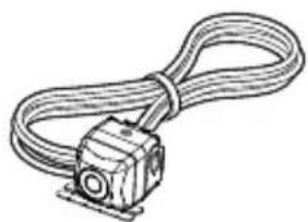
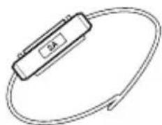
Fuse 1
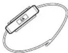
Grommet.....1
Camera bracket clamping screw.....1

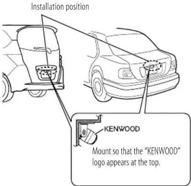
Recommended Installation Position
Examples of correct camera installation on the rear of the vehicle
Installing the Camera/Adjusting its angle
1 Decide the camera installation position.
2 Clean the camera installation surface.
Using a commercially available cleaner, wipe dirt, moisture and oil away from the surface on which the camera bracket is to be attached.
3 Loosen the camera bracket retaining screws.
Using a commercially available Phillips screwdriver, loosen the two retaining screws.
Perform steps 4 and 5 only when they are required.
4 If required, separate the camera bracket from the camera and adjust the shape according to the surface on which it will be attached.
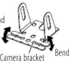
Bend
Adjust the camera bracket shape so that it fits the camera installation position.
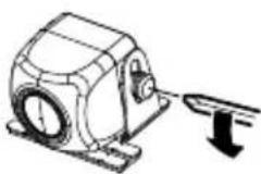
5 Mount the camera on the camera bracket.
Mount so that the "KENWOOD" logo appears at the top.
Fix the camera temporarily with tape, etc.
Using a piece of tape, etc., fix the camera temporarily.
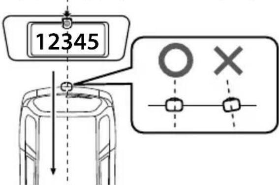
Install the camera at the center of the vehicle and not to hide the number plate. Install the camera straight toward the forward/reverse direction of the vehicle. Be careful not to lean the camera as it will effect the viewing image.
7 Complete all of the required connections.
8 Display the camera video.
Before viewing the camera, apply the parking brake and chock the wheels so that the vehicle will not move.
Otherwise, an unexpected accident may result.
For displaying the camera video, read the instruction manual for your video monitor.
Change the shift lever to the R (Reverse) range to view the image of the rear of the vehicle.
9 Adjust the camera angle.
When adjusting the camera angle, be careful not to stretch the camera cord.
Adjust the angle so that the rear of the vehicle or the bumper can be seen at the bottom of the monitor.
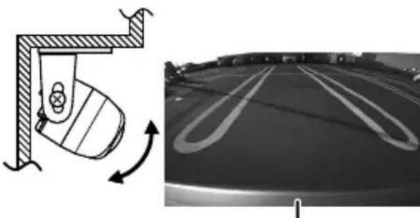
Vehicle rear part or bumper
10 After adjusting the camera angle, tighten the retaining screws firmly.
Inspect the retaining screws at times. If they are loose, tighten them firmly.
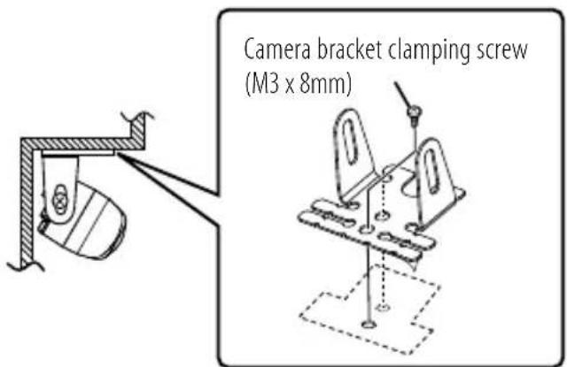
11 Fix the camera firmly in position.
Peel off the paper liner from the double-side adhesive tape on the camera bracket and attach it. After attaching, push the camera bracket with your finger to ensure close adhesion. Do not touch the adhesive surface with your hand or peel and reattach an attached tape, as these will degrade the adhesive force and may cause the camera bracket to be detached. If required, secure the bracket on the vehicle body using the camera bracket clamping screw.
The camera bracket has two holes for the screw. Select one of them to fit the position of the attachment.
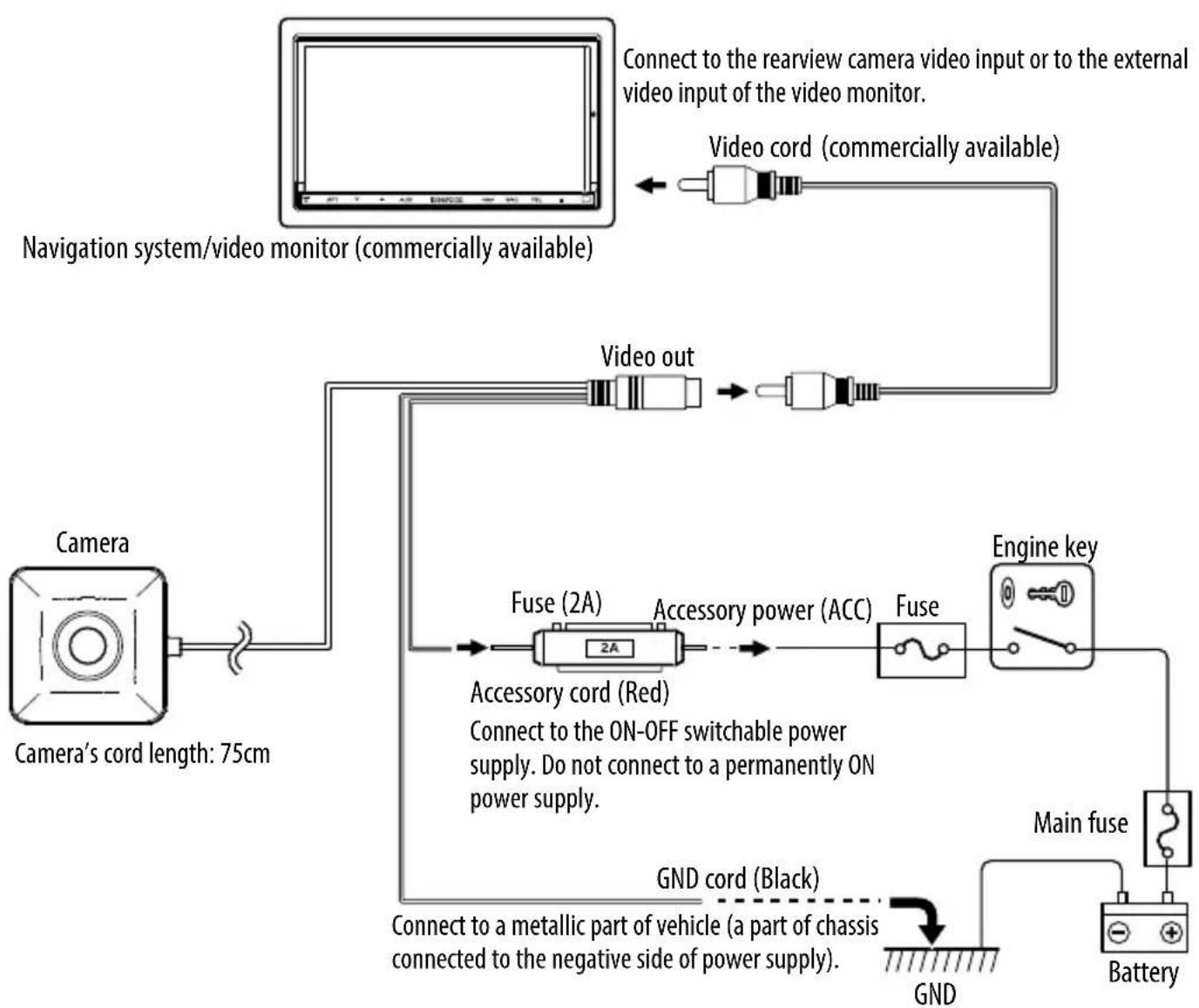
Basic Connections
CAUTION
- If the engine key of your vehicle does not have the ACC position, connect the red wire to a power source that is active when the key is ON position.
- Before proceeding to connections, make sure that the engine key is not inserted and disconnect the () terminal of the battery to prevent a possible short circuit.
Camera Unit
Output video
: Wide-angle mirror image (for rearview)
Sensor: 1/4-inch color CMOS sensor
Number of pixels: Approx. 380,000 pixels
Lens
:Wide angle,Focal length f = 1.12mm Fvalue2.2
Angles of view
: Horizontal: Approx. 129^
: Vertical: Approx. 104^
Video output: 1.0Vp - p / 75
Illumination range: Approx. 0.9 to 100,000 lux
Iris system: Electronic iris
Scanning system: Interlace
Synchronizing system: Internal synchronization
Dimensions (WxHxD): 23.4 × 23.4 × 23.9 ~mm
Weight: Approx. 21 g (without cable)
General
Operating voltage: 14.4V (9.0V - 16.0V)
Max. current consumption: 60mA
- Mirror image means that the video image inverts the left and right just like the image seen on the rearview mirror or a side mirror.
- Specifications subject to change without notice.
Information on Disposal of Old Electrical and Electronic Equipment and Batteries (applicable for countries that have adopted separate waste collection systems)
Products and batteries with the symbol (crossedout wheeled bin) cannot be disposed as household waste.

Pb
Old electrical and electronic equipment and batteries should be recycled at a facility capable of handling these items and their waste byproducts. Contact your local authority for details in locating a recycle facility nearest to you. Proper recycling and waste disposal will help conserve resources whilst preventing detrimental effects on our health and the environment.
Notice: The sign "Pb" below the symbol for batteries indicates that this battery contains lead.
AVERTISSEMENT
Telecamera [con staffa] .........1
Fusibile 1
Tensão de functi顾问amento: 14,4V (9,0 V - 16,0 V)
Consumo max. de corrente: 60 mA
Declaration of Conformity with regard to the EMC Directive
Declaration of Conformity with regard to the RoHS Directive 2011/65/EU
Manufacturer:
JVC KENWOOD Corporation
3-12 Moriya-cho, Kanagawa-ku, Yokohama-shi, Kanagawa, 221-0022, Japan
EU Representative:
JVCKENWOOD NEDERLAND B.V.
Amsterdamseweg 37, 1422 AC UITHOORN, The Netherlands