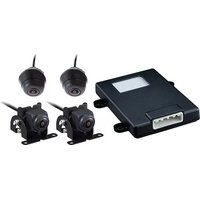
KCA-2020AVM - Rear Camera KENWOOD - Free user manual and instructions
Find the device manual for free KCA-2020AVM KENWOOD in PDF.


| Product Type | 360° Multi-View Camera System |
| Brand | Kenwood |
| Model | KCA-2020AVM |
| Number of Cameras | 4 (Front, Rear, Left, Right) |
| Image Sensor | 1/4" CMOS, 2.8μm pixel size |
| Video Resolution | 1280 x 720 @ 30 fps |
| Horizontal Viewing Angle | 192° ± 4° |
| Vertical Viewing Angle | 115° ± 4° |
| Video Output Format | AHD |
| Waterproof Rating | IP69K |
| ECU Operating Voltage | DC 9V – 16V |
| ECU Operating Current | < 0.8 A at 12V |
| ECU Max Current | < 1.05 A at 12V |
| ECU Dark Current | < 0.1 mA |
| Camera Working Current | 100 ± 20 mA at 4.6V |
| Operating Temperature (Camera) | -30°C to +80°C |
| Storage Temperature (Camera) | -40°C to +90°C |
| Key Functions | 360° bird’s-eye view, dynamic guidelines, turn signal activation, auto/manual calibration |
| Maintenance | Clean lens with soft damp cloth; avoid high-pressure water |
| Safety Precautions | Do not rely solely on camera; always check surroundings visually |
| Compatible Receivers | Select Kenwood DMX/DDX models (see manual) |
Frequently Asked Questions - KCA-2020AVM KENWOOD
User questions about KCA-2020AVM KENWOOD
0 question about this device. Answer the ones you know or ask your own.
Ask a new question about this device
Download the instructions for your Rear Camera in PDF format for free! Find your manual KCA-2020AVM - KENWOOD and take your electronic device back in hand. On this page are published all the documents necessary for the use of your device. KCA-2020AVM by KENWOOD.
USER MANUAL KCA-2020AVM KENWOOD
OPERATIONS MANUAL INSTALLATION MANUAL CALIBRATION MANUAL
Take the time to read through this instruction manual.
Familiarity with installation and operation procedures will help you obtain the best performance from your 360° Camera.
Table of Index
OPERATIONS MANUAL...... 4
INSTALLATION MANUAL.... 10
CALIBRATION MANUAL.... 29
Driving Precautions Background / Introduction
The 360° Camera plays a subsidiary device in order to help driver checking surroundings around the vehicle. Please be sure that before driving, the visual check vehicle surroundings with mirrors before ready to go is necessary. Please pay attention to the following notices and instructions when using the 360° Camera.

CAUTION
- Drivers shall not depend on the 360° Camera only. There have some different tolerance from the image and the actual object.
- Be sure to check vehicle surroundings visually before driving.
- When use 360irc Camera, not only focus on monitor, but please also use vehicle mirrors to check actual conditions.
- The position of guide line displayed on the monitor may differ from actual condition. Please check surround actual condition.
- When the tire size changed, the guide line position displayed on the screen will also be different.
Notice
- Do not use high-pressurized water column to wash 360irc Camera to avoid damage.
- The distances between the vehicle and objects may differ from the actual distance.
- There are blind spots around the vehicle so will not be displayed in 360° Camera.
- The light condition around each camera is different, so light displayed on the image may differ.
- The images from four cameras are combined. The border of the four image clarity may decline which is normal.
- The car display image may differ from actual car, purpose is to simulate car's surrounding.
360° Camera System has 4 cameras installed at front / rear and left / right side mirror of the car, where its 360-degree bird's eye view is displayed on the Display Audio for guidance of blind spot areas against the car.
Information
The screen illustrations used in this manual are examples, and may different from the image of actual car displayed on unit.
360° Camera Features
- Assist blind spot area visibility by seamless image with front, back or left and right view.
- 360° Camera guide line design, seizing distance between periphery obstacles and vehicle itself.
- Front/rear guideline refers to car width which design to assist low speed reversing or driving.
- Due to safety concerns, there will be a black mask area on top of the front view.
- When speed is over 15 ± 5 km/h, the 360irc Camera will deactivate and enter in 360irc Camera mode.(H/U "CAM" button can be forced to switch, and is not restricted by this condition)
- Turn signal mode activated when user turn on LH/RH signal below 15 ± 5 km / h .
360° Camera Operation
Press CAM button to enter 360° Camera mode.

Gear: Reverse Mode (R)
After the reverse gear is engaged, Display Audio will display the panoramic image specified in the reverse mode (please refer to the figure below).

Note
Please carefully check the surrounding as some blind spot zone will not be captured by the camera.
- The image show surrounding bird view and rear view to assist driver.
- Please be aware the distance with periphery obstacle.
- The panoramic image is a simulated aerial view. When the obstacle is close to the car, please stop the car and confirm actual secure distance before you go.
In Reverse mode, you may press the view switch to choose rear view or 360° view + rear view or 360° view + rear top veiw.
360irc view + rear view

Rear view

360° view + rear top view

Gear: Parking / Neutral / Drive Mode (P/N/D)
The car will keep displaying the 360° Camera-ahead image mode if the shift lever at P/N/D and the speed under 15 ± 5 km/h.

Note
Image show is to aid in identifying periphery obstacle during low-speed driving.
- Due to safety concerns, the front view will not show the whole image. There will be a black mask area on top of the front view.
- The front guide line has blue lines. Please pay more attention to the distance with periphery obstacles when you drive.
- When you reverse, please use left/right side mirror to check surrounding area. Press icons to switch to different view.
360° view + front top view

Front view

360° view + front right view

360° view + rear right view

360° view + rear left view

360° view + front left view

Rear view

Note
360° Camera only available for car speed is under 15 ± 5 km/h (P/N/D mode).
360° Camera view will go to audio system when the car speed is higher than 15 ± 5 km/h.
(H/U "CAM" button can be forced to switch, and is not restricted by this condition).
Turn Signal Mode
When the driver turn the left or right signal on and the speed is under 15 ± 5 km/h, The side view will be triggered.
360° view + 3D RH side view

360° view + 3D LH side view

Blind spot
The aerial panoramic image comes from the use of optical principle, where intersection parts of four cameras are for image clipping process to build panoramic effect, hence, four connection parts of images listed below would cause image to temporarily disappear and drivers are requested to pay special attention.

natural_image
Top-down line drawing of a car viewed from the side, showing front and rear views with no text or symbols.
natural_image
Side profile line drawing of a modern SUV on a paved surface (no text or symbols)Objects may not be detected from some angles. The objects underneath the bumper or on the ground may not be detected when they are displayed at front or rear viewing angle (Grey parts in oblique lines).
- The images from four cameras are in color difference under versified light source due to light incoming angle discrepancies, which is normal.
- The guide lines in the front left/right side of car mode are aligned due to shooting position/angle difference from left/right rear mirrors; however, mild staggered position of doors is normal.
- 360irc Camera display area is constricted, where the further part from the car body will present image deformation, which is normal.
- 360irc Camera are precision device. Do not hit camera, which might cause abnormal situations like failure or damage.
- 360° Camera is to aid and reinforce display of periphery blind areas against the car body. When you drive, you still must make use of the left/right side mirrors and rear view mirrors.
- When you reverse, some conditions (Ex.: weather, light) might constrict image. Do not drive your car only by the display.
- 360° Camera image might be affected or incorrect with the change of tire size; hence, we do not suggest you to change tire size.
- Heavy impact or displacement from collision might cause 360° Camera image to diverge right or left, worsening image connection. To resume normal operations, image calibration and part replacement may be required.
If You Notice Any Symptoms
Troubleshooting will help you to simply identify the most likely cause and restore the process to working status. Whenever you have a problem with the 360irc Camera, here are some basic troubleshooting techniques that can help you to fix issues.
Please identify the following symptoms and most likely cause to find the solutions.
| Symptom Likely cause Solution | ||
| Difficult to see the image | ·The vehicle is in a dark area.·The temperature around the lens is either high or low.·The outside temperature is low. | Please move car away from the uneven light or direct sunlight. |
| ·There are water droplets on the camera.·The surroundings is raining or humid. | Please move the car to the room temperature. | |
| ·External factor (mud etc.) is adhering to the camera.·Sunlight or headlights is shining directly into the camera.·The vehicle is under fluorescent lights, sodium lights, and mercury lights etc. | Please clean the camera with water and soft cloth. | |
| The image is blurry | Dirt or external factors (like water droplets, snow, and mud etc.) attached to the camera. | Clean the camera with water and soft cloth. |
| The image is out of alignment | The camera or surrounding area got a strong impact. | Please have your dealer to check the vehicle. |
| The guide lines are out of alignment | The camera position is out of alignment. Please have your dealer to check the vehicle. | |
| ·The vehicle is tilted. (Heavy load, tire puncture, etc.)·The vehicle is in a slope status. | This is not malfunction. Please check surroundings visually when reversing the car. | |
There will be some discrepancy in the contents of this user's manual due to the technical evolution and the software improvement.
Please follow the actual function display. This manual is only for users' operating reference.

WARNING
To prevent injury or fire, take the following precautions:
- To prevent a short circuit, never put or leave any metallic objects (such as coins or metal tools) inside the unit.
- Installation and wiring of this product require specialist skill and experience. To assure your safety, please request a specialist technician to install the unit.
- When you make a hole to install the camera, check the location of pipes, tanks and wiring and avoid touching them. Otherwise it may cause the fire.
- When you make a hole with a drill, use goggles to protect your eyes.

CAUTION
To prevent damage to the product, take the following precautions:
- Make sure to ground the unit to a negative 12V DC power supply.
- When replacing a fuse, only use a new fuse with the prescribed rating. Using a fuse with the wrong rating may cause your unit to malfunction.
- Do not use your own screws. Use only the screws provided. If you use the wrong screws, you could damage the unit.
NOTE
- A rear view camera is a camera that provides symmetrical images in the same way as rear and side view mirrors.
- Connection to a TV with an RCA video input is possible, but confirm whether the TV you use has a reverse gear connection function.
- This product is designed to supplement the driver's rear view, but the camera images do not show all dangers and obstacles. Be sure to look behind you when reversing to confirm the view.
- This product features a wide-angle lens, so the near view is wide and the far view is narrow, which may create a false sense of distance. Be sure to look behind you when reversing to confirm the view.
- Do not wash your car with an automatic car wash or high-pressure water as it may result in water entering the camera or the camera falling off.
- Check camera bracket installation before driving. Are the screws loose?
- Is the camera bracket firmly secured?
- If the rear view camera comes loose while you are driving
it may cause an accident. Before finally installing the unit, connect the wiring temporarily, making sure it is all connected up properly, and the unit and the system work.
- When mounting this unit, make sure none of the leads are trapped between this unit and the surrounding metalwork or fittings.
- Do not mount this unit near the heater outlet, where it would be affected by heat, or near the doors, where rainwater might splash onto it. (Never install in locations such as the above because of the danger of malfunction due to high temperatures.)
- Before drilling any mounting holes always check behind where you want to drill the holes. Do not drill into the gas line, brake line, electrical wiring or other important parts.
- If this unit is installed in the passenger compartment, anchor it securely so it does not break free while the car is moving, and cause injury or an accident.
- If this unit is installed under a front seat, make sure it does not obstruct seat movement. Route all leads and cords carefully around the sliding mechanism so they do not get caught or pinched in the mechanism and cause a short circuit.
Care and maintenance
- When the product gets dirty, wipe dry with a silicon cloth or soft cloth. If it is seriously stained, remove stain with a cloth moistened with a neutral cleaner and then wipe the cleaner away. Do not use a hard cloth and/or a volatile substance such as lacquer thinner or alcohol, scratches, deformation, degradation and/or damage may result.
- When a lens component gets dirty, wipe gently with a soft cloth moistened with water. Do not rub with a dry cloth to prevent scratching the lens.
Installation Procedure
1 To prevent a short circuit, remove the key from the ignition and disconnect the - battery.
2 Make the proper input and output wire connections for each unit.
3 Connect the wiring harness wires in the following order: ground, ignition and camera unit.
4 Install the unit in your car.
5 Reconnect the - battery.

WARNING
- If you connect the ignition wire (Red) to the car chassis (Ground), you may cause a short circuit, that in turn may start a fire. Always connect those wires to the power source running through the fuse box.
- Do not cut out the fuse from the ignition wire (Red). The power supply must be connected to the wires via the fuse.

CAUTION
- If your car's ignition does not have an ACC position, connect the ignition wires to a power source that can be turned on and off with the ignition key. If you connect the ignition wire to a power source with a constant voltage supply, as with battery wires, the battery may die.
- If the fuse blows, first make sure the wires aren't touching to cause a short circuit, then replace the old fuse with one with the same rating.
- Insulate unconnected wires with vinyl tape or other similar material. To prevent a short circuit, do not remove the caps on the ends of the unconnected wires or the terminals.
• After the unit is installed, check whether the brake lamps, blinkers, wipers, etc. on the car are working properly.
• Install so that it does not obstruct the rear field of view.
• Install so that it does not protrude from the side of the car. - Do not perform installation in rain or fog.
- When humidity is high, dry the surface to which the unit is to be attached before installing.
- Moisture on the attachment surface reduces adhesive strength, which may lead to the unit coming off.
- Do not attach the camera bracket to areas on the car body treated with fluorocarbon resin, or glass.
- May result in the rear view camera falling off.
- Do not apply water to the unit.
- Do not expose the unit to rain.
- Do not subject the camera to unnecessary force.
- Thoroughly clean where tape is used for sticking on the unit.
- Refer to the Instruction's manual for details on connecting the other units, then make connections correctly.
- Secure the wiring with cable clamps or adhesive tape. To protect the wiring, wrap adhesive tape around them where they lie against metal parts.
- Route and secure all wiring so it cannot touch any moving parts, such as the gear shift, handbrake and seat rails.
-
Do not route wiring in places that get hot, such as near the heater outlet. If the insulation of the wiring melts or gets torn, there is a danger of the wiring short-circuiting to the vehicle body.
-
When replacing the fuse, be sure to use only fuse of the rating prescribed on the fuse holder.
- To minimize noise locate the TV antenna cable, radio antenna cable and RCA cable as far away from each other as possible.
- Lay the cords by avoiding high-temperature areas. Use corrugated tubes for wiring inside the engine room. If a cord contacts a high-temperature area of the vehicle, the coating may melt and cause short-circuiting, which may lead to a fire or electric shock hazard.
Pre check before installation

(Important)
This camera system consists of four cameras and it is necessary to install side camera inside the side-mirror housing.
Before selling this unit, please check the side-mirror structure and confirm the space to install side camera is enough
*More than 32±2mm (width) / 14±2mm (height)
| Compatibility list Product name | |
| KENWOOD Receiver | (MY20)DMX9720XS/DMX9720XDS(MY21)DMX9021S/DMX8521S(MY20)DMX9020DABS/DDX920WDABS/DDX8020S/DDX820WS/DMX8020S/DMX820WS/DMX8520DABS(MY19)DDX7019BT/DDX719WBT/DMX7019BT/DMX719WBT |
*MY19 HD series (DDX9019S/DDX919WS/DDX9019DABS/DNX series) is NOT compatible for this system.
*Impossible to connect DRV-N520 (Dashcam) and KCA-2020AVM in parallel.
(Either can be connected)
Parts list
Front/Rear camera section

natural_image
Technical line drawing of mechanical assembly with components like a spring, housing, and shaft (no text or labels)Left/Right camera section

natural_image
Exploded view diagram of a mechanical component showing internal parts and assembly (no text or labels)ECU Box

natural_image
Technical line drawing of a rectangular electronic device with two mounting holes and a central internal component (no text or symbols)(Others)
• Full Wiring • Instruction manual
- Double side tape
- Calibration manual
*To complete calibration easily, it is recommended to use calibration sheet.
(Optional item, please contact to Kenwood sales company)
Preparation for Install
To complete installation, below special tool is required.
• 22mm Drill bit to make a hall in the side mirror
- Calibration sheet
(Kenwood company handles it and please contact to it if you need)
Example of drill bit

natural_image
Two types of drill bit holders shown side by side (no text or symbols visible)
natural_image
Pure geometric diagram with black square and dimension lines, no text or symbols present
- If you make a calibration sheet, please be noted for below points:
Calibration Area Requirement:
| Item Requirement Comment | ||
| Calibration Space According to different cars model | ||
| Pattern Color Black & White | ||
| Ground Color | Matte color, not reflective. It can be gray surface & unpainted. | |
| Wall Color | Same as ground color. | |
| Illumination | Around 600 lux, white light | |
| Illumination Direction | All lights should be on the ceiling facing down. | No angles to avoid undesired shadows. |
Connection Chart of KCA-2020AVM to Kenwood Receiver

flowchart
graph TD
    A["To ECU/AVM"] --> B["TRNL"]
    B --> C["LH"]
    B --> D["RH"]
    B --> E["RR"]
    B --> F["FR"]
    B --> G["To Left side Camera connector"]
    B --> H["To Right side Camera connector"]
    B --> I["To Rear Camera connector"]
    B --> J["To Front Camera connector"]
    C --> K["To Turn signal wire in the vehicle"]
    D --> L["To Back up power"]
    E --> M["To Accessory power"]
    F --> N["GND"]
    G --> O["B+"]
    H --> P["KENWOOD H/U Reverse line"]
    I --> Q["SPD"]
    J --> R["Car Reverse Line"]
    K --> S["To Speed-Pulse sensor (if you don't connect, PVM still works)"]
    L --> T["To Reverse gear sensor in the car"]
    M --> U["To Reverse input in the Kenwood receiver (NOT reverse line of vehicle!)"]
    N --> V["To Back up power"]
Remark1: Phrase connect rightly for reserse line
Remark2: If the signal pulse of speed/turn signal from vehicle ECU doesn't match the spec of KCA-2020AVM, please do not connect them.
(Even disconnecting speed/turn signal sensor to KCA-2020AVM, some of view mode doesn't work but basic feature can work)
Install the camera unit / camera location/direction guide
◆ Front Camera

| Description Value | ||
| W Camera X pos. Vehicle width / 2 (if possible) | ||
| H Camera Z pos. (height) > 600mm | ||
| θt Tilt angle > 20 deg. | ||
| θp Pan angle 90° | ||
| θr Roll angle 0° | ||
| VB Car body occupation > 10% | ||
(Front Camera section)
Key point to install Front camera is the location and camera angle.
(Angle of Camera must be more than 20-30 degree)
Install the camera unit / camera location/direction guide
- Rear Camera

| Description Value | ||
| W Camera X pos. Vehicle width / 2 (if possible) | ||
| H Camera Z pos. (height) >600mm | ||
| θt Tilt angle >20 deg. | ||
| θp Pan angle 90° | ||
| θr Roll angle 0° | ||
| VB Car body occupation around 10% | ||
(Rear Camera section)
Key point to install Rear camera is the location and camera angle.
(Angle of Camera must be more than 20-30 degree)
Install the camera unit / camera location/direction guide
- Left Camera

| Description Value | ||
| H Camera Z pos. (height) > 600mm | ||
| θt Tilt angle > 20 deg. (45 degree is better) | ||
| θp Pan angle 95° | ||
| θr Roll angle 5° | ||
| VB Car body occupation 10% one-third is better | ||
(Right Camera section)
Key point to install Right camera is the angle.
*Be careful for t (Tilt Angle: must be 20 degree) and p (Pan angle: must be 90-100 degree, the best is 95 degree)
Install the camera unit / camera location/direction guide
- Right Camera

| Description Value | ||
| H Camera Z pos. (height) > 600mm | ||
| θt Tilt angle > 20 deg. (45 degree is better) | ||
| θp Pan angle 95° | ||
| θr Roll angle 5° | ||
| VB Car body occupation 10% one-third is better | ||
(Left Camera section)
Key point to install Left camera is the angle.
*Be careful for t (Tilt Angle: must be 20 degree) and p (Pan angle: must be 90-100 degree, the best is 95 degree)
Front Camera(FR) assembly installation

natural_image
Close-up of a mechanical component mounted on a metal frame, showing a small bracket and hexagonal lattice structure (no text or symbols visible)
natural_image
Mechanical assembly diagram showing a shaft and housing with mounting holes (no text or labels)Lock with ∅3 Self-tapping screw on car's front air dam with adhesive tape on the button of BKT.
Angle lock screw
Each graduation is 15 degree

natural_image
Mechanical assembly diagram showing a cam mechanism with rotating components and directional arrows (no text or labels)Angle adjust screw
Pigtail wiring of camera

Suitable
camera angle
20\~30degree
Rear Camera (RR) assembly installation(Horizontal mount installation)

natural_image
Front view of a Toyota car's rear grille with logo and license plate (no visible text or symbols)
natural_image
Mechanical component diagram showing a 43mm dimensioned view with no visible text or symbols

natural_image
Cross-sectional diagram of a mechanical component with mounting holes and an upward arrow indicating force or direction (no text or symbols)This BKT for horizontal installation


natural_image
Technical illustration of a mechanical assembly with mounting flanges and internal components (no text or symbols)Remark: all the screws on BKT are coated NYLOK paint to prevent loosening

As well as Front Camera installation, Camera angle must be 25-30 degree.
Rear Camera(RR)assembly installation(vertical mount installation)
For some car which we can not install rear-camera with horizontal mount of bracket, it is possible to install vertical mount by changing the bracket location.
Example: Impossible to install with horizontal mount

natural_image
Close-up of a vehicle's front panel with control knobs and a rectangular frame (no visible text or symbols)How to change the bracket position from horizontal to vertical.

Besuretolockthe screw after the anglefixed.(25-30 degree)


natural_image
Technical diagram of a mechanical component with arrows indicating direction (no text or symbols)Drilling lock ∅3 self-tapping screws.
Installation Manual
Side Camera assembly installation

natural_image
3D rendered mechanical component with layered structure and cylindrical base (no visible text or symbols)Basic structure of side camera (Camera unit: Common with L/R)

Note
Camera has to be installed for right direction, otherwise side vision can not be shown correctly and calibration must not be done properly!
Step 1: Find the suitable location of side camera
At least 32mm x 14mm space is required to install side camera and the surface to place side camera must be as flat as possible.

natural_image
Close-up of a mechanical component with multiple bolt holes and mounting brackets (no visible text or symbols)
Step 2: Marking
1:Pressing the lens to the bottom, use the outside of the lens as a reference, and use a marker to draw the outer limit position of the lens.
2.Remove the lens set to measure the thickness of the lens.(Above example is about 9\~10mm)

natural_image
Two black-and-white photos showing a hand adjusting a car's side mirror and a caliper (no visible text or symbols)Step 3: Find the accurate position
3: Use a ruler to measure 9\~10mm (lens thickness) inward based on the outer limit position, and then mark the inner limit position of the lens. The drilling must be inside the extreme position inside the lens to avoid interference of lens.

Remarks: To avoid the interference of back mirror, this measurement process is very important.
Step 4: Cut the rib or wall inside the mirror housing
4-1/#4-2:after finding the suitable location of side camera and if some of the rib or wall (inside mirror housing) interferes to install its camera, please cut and remove them.

Step 5: Drill the hole in side mirror housing
5-1/#5-2:The drilling position must be inside the extreme position. Drill ∅22 round holes for the left and right rear mirrors (the rear mirrors need to be fixed horizontally).
The drilling position must be flat and not curved.
The drilling position of the L&R mirror hole must be same.


Use 22mm drill bit to make a hall in the housing
(Drill bit is NOT included in this product and please prepare drill bit in your side)
Example of drill bit

natural_image
Two types of drill bit holders shown side by side (no text or symbols visible)Side camera assembly
Step 6: Install side camera
6-1/#6-2: After the drilling is completed, install the side cameras.
The camera body and the rubber lock washer must be installed outside the rear mirror.
The lock nut and plastic washer must be installed inside the rear mirror.
Tighten the lock nut and confirm camera can not be moved and not to be interfered to other unit inside the mirror.


natural_image
Close-up of a hand inserting a component into a device housing (no visible text or symbols)Tighten the lock nut with suitable torque
(Important!) Direction of side camera unit
Side camera unit must face toward the right direction.
You can see the direction arrow in the camera unit (#Arrow indicator) toward up and 90 degree for the vehicle direction then complete tightening the camera assy.


Step 7: Confirm side camera direction
Before completing re-assemble mirror unit, confirm camera unit faces right direction.
Check the configuration page (P16-17)

natural_image
3D wireframe model of a vehicle's front and side panels, showing structural components without any text or symbolsThis angle must be between 20-45 degrees

natural_image
Close-up of a car's side mirror and headlight on a surface, no visible text or symbolsEven if camera unit angle is out of 20-45 degrees, Auto calibration might be done, or please complete it by manual calibration.
Step 8: Connect the wire to the receiver
When the whole line is complete, the joint at the circled position in the above figure must be inserted into the shaft line hole Connectors need to be connected to the one with the same wire color.

Camera Installation Example(Front/Rear)

natural_image
Black-and-white interior view of a large industrial facility with circular structural elements and overhead lighting (no visible text or symbols)
Camera Installation Example( Left /Right )


Camera Installation Position Suggestion


natural_image
Close-up of a car's front wheel and dashboard, showing a magnified view of the wheel (no text or symbols visible)From picture quality point of view, if possible, we suggest to install left/right camera at the position as left picture above.
Calibration Pattern Placement Requirement

We require the whole calibration pattern can be saw in each camera view when doing calibration. If part of pattern was covered by vehicle body, such as the left picture above, it will increase the probability of calibration fail.

natural_image
Black-and-white fisheye view of a car interior with structural elements and no visible text or symbols1. Park the car correctly at the calibration site.
1 Calibration pattern
- Please follow different car model to place calibration cloth's location and size.
- Please park at the middle of Width/Lenght.
- Please place calibration cloth according to different car model's Width/Lenght distance and make sure the accuracy.
- Now D1/D2/D3 value will be justified to match Width/Lenght value. Please make sure it will with in region of interest range. Width/Lenght value should be same as below table.
| # Car name (TGT Car) 2019 Jan-Dec sales QTY Lenght Width Height Type Vehicle Group | |||||||
| 11 Brio 73,904 3,815 1,680 1,485 Comapact | NO1 | ||||||
| 14 Fit (Jazz) 54,690 3,990 1,695 1 525 Comapact | |||||||
| 7 Avanza 87,865 4,140 1,660 1,695 Small MPV | NO2 | ||||||
| 26 Xenia | 21,674 4,140 1,660 1,695 Small MPV | ||||||
| 32 Senta | 5,739 4,260 1,695 1,675 Comapact | NO3 | |||||
| 15 HR-V | 51,928 | 4,334 | 1,772 | 1,605 | Small SUV | ||
| 4 Ertiga | 126,752 4,395 1,735 1,690 Small MPV | ||||||
| 13 Rush | 65,855 4,435 1,695 1,705 Small MPV | NO4 | |||||
| 24 Terios | 22,960 4,435 1,695 1,705 Small SPV | ||||||
| 10 Honda City | 74,372 4,440 1,694 1,477 Comapact | ||||||
| 20 Vios | 36,772 4,425 1,730 1,475 Comapact | NO5 | |||||
| 30 BR-V | 15,281 | 4,456 | 1,735 | 1,666 | Small MPV | ||
| 5 Xpander | 98,635 4,475 1,750 1,700 Small MPV | ||||||
| 16 CR-V | 50,426 4,670 1,855 1,680 Middle SUV | NO6 | |||||
| 22 RAV4 | 24,260 4,600 1,855 1,690 Middle SUV | ||||||
| 6 Corolla | 92,479 4,630 1,780 1,435 Sedan | NO7 | |||||
| 17 Civic (Sedan) | 49,580 4,650 1,800 1,415 Sedan | ||||||
| 25 X-Trail | 22,865 4,670 1,820 1,749 Middle SUV | ||||||
| 27 Outlander | 21,389 4,690 1,815 1,680 Middle SUV | ||||||
| 3 Innova | 128,099 4,735 1,830 1,795 MPV | ||||||
| 19 Pajero Sport | 39,273 4,785 1,815 1,805 | ||||||
| 9 Fortuner | 76,375 4,795 1,850 1,865 Large SUV | ||||||
| 28 MU-X | 20,440 4,825 1,860 1,860 Large MPV | NO8 | |||||
| 29 Land Cruiser Prado | 19,135 4,840 1,885 1,880 Large SUV | ||||||
| 33 Accord (CR1/2/3) | 5,193 4,862 1,849 1,466 Sedan | ||||||
| 21 Camry | 34,753 4,885 1,840 1,445 Sedan | NO9 | |||||
| 31 Alphard | 7,666 4,925 1,850 1,895 Large MPV | ||||||
| 23 Land Cruiser | 23,829 4,950 1,970 1,905 Large SUV | ||||||
| 12 Triton (L200) | 72,925 5,210 1,820 1,780 Pick up truck | NO10 | |||||
| 18 Frontier (Navara) | 37,371 5,255 1,850 1,820 Pick up truck | ||||||
| 2 D-Max (2nd gene.) | 170,117 5,295 1,860 1,795 Pick up truck | ||||||
| 1 Hlux | 219,131 5,330 1,855 1,815 Pick up truck | ||||||
| 8 Ford Ranger | 78,520 5,446 1,977 1,821 Pick up truck | NO11 | |||||
Calibration Pattern
(Important) Each calibration sheet has different specs and it must be located accurately.
If the location of calibration sheet is incorrect, the calibration process must fail.
Especially the distance of D1/D2/D3 is important and please follow the instruction in the following page.

flowchart
graph TD
    A["Calibration sheet FL"] --> B["Distance between front bumper end and the cut line of calibration sheet (FR & FL)"]
    C["Calibration sheet FR"] --> D["Distance between side-end of the body and the cut-line of the sheet."]
    E["Calibration sheet RR"] --> F["Distance between rear bumper end and the cut line of calibration sheet (RR & RL)"]
    G["Calibration sheet RL"] --> H["Distance between front bumper end and the cut line of calibration sheet (FR & FL)"]
    I["Calibration sheet FR"] --> J["Distance between side-end of the body and the cut-line of the sheet."]
    K["Calibration sheet RL"] --> L["Distance between rear bumper end and the cut line of calibration sheet (RR & RL)"]
Distance of D1/D2/D3


Vehicle Group NO.1 unit : mm

flowchart
graph TD
    A["(D1) 500"] -->|W 2300| B["(L) 5200"]
    A -->|100100| C["(D2) 300"]
    A -->|100100| D["(D3)"]
    A -->|100100| E["(L)"]
Vehicle Group NO.2 unit : mm

flowchart
graph TD
    A["(W)"] --> B["(D1) 500"]
    B --> C["(L) 5340"]
    C --> D["(D2) 300"]
    D --> E["(D3)"]
    E --> A
    style A fill:#f9f,stroke:#333
    style B fill:#ccf,stroke:#333
    style C fill:#cfc,stroke:#333
    style D fill:#fcc,stroke:#333
    style E fill:#cff,stroke:#333
Vehicle Group NO.3 unit : mm

flowchart
graph TD
    A["(W)"] --> B["(D1) 500"]
    B --> C["(L) 5600"]
    C --> D["(D2) 300"]
    D --> E["(D3)"]
    E --> A
    style A fill:#f9f,stroke:#333
    style B fill:#ccf,stroke:#333
    style C fill:#cfc,stroke:#333
    style D fill:#fcc,stroke:#333
    style E fill:#cff,stroke:#333
Vehicle Group NO.4 unit : mm

flowchart
graph TD
    A["(W)"] --> B["(D1) 500"]
    B --> C["(D2) 300"]
    C --> D["(L) 5600"]
    D --> E["(D3)"]
    E --> A
    style A fill:#f9f,stroke:#333
    style B fill:#ccf,stroke:#333
    style C fill:#cfc,stroke:#333
    style D fill:#fcc,stroke:#333
    style E fill:#ffc,stroke:#333
Vehicle Group NO.5
unit : mm

flowchart
graph TD
    A["(W)"] --> B["(D1) 500"]
    B --> C["(D2) 300"]
    C --> D["(L) 5680"]
    D --> E["(D3)"]
    E --> A
    style A fill:#f9f,stroke:#333
    style B fill:#ccf,stroke:#333
    style C fill:#cfc,stroke:#333
    style D fill:#fcc,stroke:#333
    style E fill:#ffc,stroke:#333
Vehicle Group NO.6
unit : mm

flowchart
graph TD
    A["(W)"] --> B["(D1) 500"]
    B --> C["(L) 5800"]
    C --> D["(D2) 300"]
    D --> E["(D3)"]
    E --> A
    style A fill:#f9f,stroke:#333
    style B fill:#ccf,stroke:#333
    style C fill:#cfc,stroke:#333
    style D fill:#fcc,stroke:#333
    style E fill:#cff,stroke:#333
Vehicle Group NO.7
unit : mm

flowchart
graph TD
    A["(W)"] --> B["(D1) 500"]
    B --> C["(D2) 300"]
    C --> D["(L) 6000"]
    D --> E["(D3)"]
    E --> A
    style A fill:#f9f,stroke:#333
    style B fill:#ccf,stroke:#333
    style C fill:#cfc,stroke:#333
    style D fill:#fcc,stroke:#333
    style E fill:#ffc,stroke:#333
Vehicle Group NO.8
unit : mm

flowchart
graph TD
    A["(W)"] -->|2490| B["(D1) 500"]
    B --> C["(L) 6090"]
    C --> D["(D2) 300"]
    D --> E["(D3)"]
    E --> F["(D1) 500"]
    style A fill:#f9f,stroke:#333
    style B fill:#ccf,stroke:#333
    style C fill:#cfc,stroke:#333
    style D fill:#fcc,stroke:#333
    style E fill:#ffc,stroke:#333
Vehicle Group NO.9 unit : mm

flowchart
graph TD
    A["(W)"] --> B["(D1) 500"]
    B --> C["(D2) 300"]
    C --> D["(L) 6150"]
    D --> E["(D3)"]
    E --> A
    style A fill:#f9f,stroke:#333
    style B fill:#ccf,stroke:#333
    style C fill:#cfc,stroke:#333
    style D fill:#fcc,stroke:#333
    style E fill:#ffc,stroke:#333
Vehicle Group NO.10 unit : mm

flowchart
graph TD
    A["(W)"] --> B["(D1) 500"]
    B --> C["(D2) 300"]
    C --> D["(L) 6530"]
    D --> E["(D3)"]
    E --> A
    style A fill:#f9f,stroke:#333
    style B fill:#ccf,stroke:#333
    style C fill:#cfc,stroke:#333
    style D fill:#fcc,stroke:#333
    style E fill:#ffc,stroke:#333
Vehicle Group NO.11 unit : mm

flowchart
graph TD
    A["(W)"] --> B["(D1) 500"]
    B --> C["(D2) 300"]
    C --> D["(L) 6650"]
    D --> E["(D3)"]
    E --> F["(W)"] --> G["(W)"] --> H["(W)"] --> I["(W)"] --> J["(W)"] --> K["(W)"] --> L["(W)"] --> M["(W)"] --> N["(W)"] --> O["(W)"] --> P["(W)"] --> Q["(W)"] --> R["(W)"] --> S["(W)"] --> T["(W)"] --> U["(W)"] --> V["(W)"] --> W["(W)"] --> X["(W)"] --> Y["(W)"] --> Z["(W)"] --> A
    style A fill:#f9f,stroke:#333
    style B fill:#ccf,stroke:#333
    style C fill:#cfc,stroke:#333
    style D fill:#fcc,stroke:#333
    style E fill:#cff,stroke:#333
    style F fill:#ffc,stroke:#333
    style G fill:#f9f,stroke:#333
    style H fill:#ccf,stroke:#333
    style I fill:#f9f,stroke:#333
    style J fill:#ccf,stroke:#333
    style K fill:#f9f,stroke:#333
    style L fill:#ccf,stroke:#333
    style M fill:#f9f,stroke:#333
    style N fill:#ccf,stroke:#333
    style O fill:#f9f,stroke:#333
    style P fill:#ccf,stroke:#333
    style Q fill:#f9f,stroke:#333
    style R fill:#ccf,stroke:#333
    style S fill:#f9f,stroke:#333
2 Calibration Site
a.Area

natural_image
Interior view of an automotive assembly line with a car on a checkered floor and workers observing (no visible text or symbols)b.Front and rear wheel alignment lines

natural_image
Black-and-white photo of a car on an assembly line with a person standing near the vehicle (no visible text or symbols)c.Wheel alignment point Front wheel stop position.

natural_image
Black-and-white photo of a car parked next to a large rectangular panel with a black square on top, showing no visible text or symbols.2 Place calibration pattern
1 Must at P / N / D Mode then touch area "A" three times.

3 You have to run auto calibration one time, then will enable manual calibration.

2 Calibration interface

4 Touch area "B" five times, then will appear red block region of interest

5 Please place pattern in the red block, You can see the entire calibration pattern is better

3 Enter the 360° Camera interface
1 Power on.

natural_image
Close-up of a finger pressing a button on a dark leather car (no text or symbols visible)2 Select CAM button.

3 Enter 360° Camera interface.

4 Select Car Dimension
1 Must at P / N / D Mode then touch area "A" three times.

- Use ← and → to select the car you want to install

other
| Model | Length | Value | | :--- | :--- | :--- | | Model 1 | 3,800-4,000 | 4,000-4,200 | | Model 2 | <1,700 | <1,700 | | Model 3 | 4,200-4,400 | <1,800 | | Model 4 | 4,400-4,600 | <1,700 | | Model 5 | 4,400-4,600 | <1,750 | 1 / 3 → BACK2 Calibration interface.


other
2 / 3 | Model | Length | Weight | | :--- | :--- | :--- | | Model 6 | 4,400 - 4,600 | <1,900 | | Model 7 | 4,600 - 4,800 | <1,860 | | Model 8 | 4,800 - 5,000 | <1,890 | | Model 9 | 4,800 - 5,000 | <1,975 | | Model 10 | 5,200 - 5,400 | <1,855 | BACK3 Select Car Dimension
- Please touch "Car Dimension"

3.Choose car model
(1)Select the car model you want to install
(2) After selecting, please press Back
(3) When you press Back icon one second, then system will re-start and then load in vehicle size you choose.

5 AUTO Calibration
1 Click "Auto Calibration".

2 Calibration in Progress.

3 View Generation in Progress.

4
- AUTO Calibration succeeded.
Continue to next step.

- If AUTO Calibration failed.
Please operate Manual Calibration. Please refer to Page 17.

| Auto calibration failure checkpoint | ||
| 1 | No image. | 1. Confirm that the connectors are properly installed.2. Confirm that the wire is not damaged.3. Make sure the camera is not malfunctioning. |
| 2 | Blurred image. | 1. Confirm removal of camera protector.2. Make sure the camera is not dirty.3. Make sure the camera has no water drops. |
| 3 | Some objects are covered to the calibration pattern. | Remove obstacles. |
| 4 | Calibration pattern stain. Please c | ean the calibration pattern. |
| 5 | Reflective. Please remove the ref | lection. |
| 6 | Detected feature point is incorrect. | Manually adjust the feature point. |
Black area of the correction pattern is not in the region of interest.
Follow these steps to confirm region of interest.
- Touch area "B" five times.

- Comfirm the black area of the calibration cloth is in the region of interest.

- If not, please make sure the calibration site is correct, pay attention to whether the parking position and calibration pattern are placed correctly.

Note: When the region of interest is displayed, the lower row icons and GEN are disabled.
5 Confirm the calibration result.
| OK NG | |||
| Four full rectangles. Incomplete rectangle. Rectangular skew. Rectangular deformation. | |||
 |  |  |  |
6
1. If the calibration result is OK.
Click "BACK" to back to the 360° Camera interface.

2. If the calibration result is NG.
Please operate Manual Calibration. Please refer to Page 43.
6 Manual Calibration
1 Click "Manual Calibration".

2 Enter Manual Calibration menu.

3 Enter the FRONT/BACK/LEFT/RIGHT camera screen to confirm the feature points.
a.Click "FRONT camera".

b.Cross feature points appears on the screen.
* This may need to wait few seconds.

c. The goal is to move six points to the black corner at the center of the cross feature point. This example is point 3 is not in the correct position.

d. Use " ← " to switch the cross feature point to point 3. The point 3 will turn orange.

e.Click "OK" to select the cross feature points. The point 3 will turn red.

f. Use the "↑"" ↓ ""←""→" to move the cross feature points.

For this case, we need to shift point 3, use " ↓ ".

g. Confirm that the black corner is at the center of the cross feature point.

natural_image
Two grayscale images showing a vehicle's front and side views, with no visible text or symbols.h.Click "OK" the point 3 to change back to orange and save the location.

i. After all six cross feature points have been confirmed, follow the step A. to step H. to confirm the cross feature points of other cameras.
FRONT BACK

LEFT RIGHT

j.Click "GEN".

k.Generation Done.

4 Manual calibration success.

5 Confirm the calibration result.
| OK NG | |||
| Four full rectangles. Incomplete rectangle. Rectangular skew. Rectangular deformation. | |||
6
- If the calibration result is OK. Click "BACK" to return to the 360° Camera interface.

- If the calibration result is NG. Please operate Manual Calibration again. Please refer to page 43.
7 Troubleshooting


natural_image
Interior view of a large industrial facility with machinery and structural elements (no visible text or symbols)Each len's image has a black non-image area at the four corners. If the position of the feature point is selected in the area of the four corners (as the square area shown as upper right image), the black screen can be displayed. At the time, you can re-calibrate automatically to return to the normal state.
| HD Camera SPEC | ||
| No. Item | SPEC | |
| 1 Optical format 1/4" | ||
| 2 Image Sensor Pixel size 2.8um*2.8um | ||
| 3 Video Resoulation 1280*720@30fps | ||
| 4 Horizontal Angle 192±4° | ||
| 5 Vertical Angle 115±4° | ||
| 6 Working Current 100 ± 20mA@4.6V | ||
| 7 Working Voltage | 4.6V | |
| 8 | Video Output Format | AHD |
| 9 | Working Temp. | -30°C ~+80°C |
| 10 | Storage Temp. | -40°C ~+90°C |
| 11 | SNR | 43.3dB |
| 12 | Dark signal | 3.5[mV/sec]@60 °C |
| 13 | Sensitivity | 22.5K[e-/Lux.sec] |
| 14 | Waterproof | IP69K |
| ECU Spec | ||
| No. Item | SPEC | |
| 1 | CPU 32bit Andes | D10 Rise,Dual-core |
| 2 Input Voltage | DC9V~16V | |
| 3 Working Temp | -30 | °C ~+80°C |
| 4 | Storage Temp | -40°C ~+90°C |
| 5 | Operating current | <0.8A@DC12V |
| 6 | Max current | <1.05A@DC12V |
| 7 | Dark current | <0.1mA |
| 8 Camera Power 4.6V | ||
KENWOOD

- Table of Index
- Driving Precautions Background / Introduction
- CAUTION
- Notice
- Information
- 360° Camera Features
- 360° Camera Operation
- Gear: Reverse Mode (R)
- Note
- Gear: Parking / Neutral / Drive Mode (P/N/D)
- Turn Signal Mode
- Blind spot
- If You Notice Any Symptoms
- WARNING
- To prevent injury or fire, take the following precautions:
- To prevent damage to the product, take the following precautions:
- Care and maintenance
- Installation Procedure
- Pre check before installation
- Parts list
- Preparation for Install
- Connection Chart of KCA-2020AVM to Kenwood Receiver
- Install the camera unit / camera location/direction guide
- Front Camera(FR) assembly installation
- Rear Camera (RR) assembly installation(Horizontal mount installation)
- Rear Camera(RR)assembly installation(vertical mount installation)
- Side Camera assembly installation
- Step 1: Find the suitable location of side camera
- Step 2: Marking
- 1:Pressing the lens to the bottom, use the outside of the lens as a reference, and use a marker to draw the outer limit position of the lens.
- 2.Remove the lens set to measure the thickness of the lens.(Above example is about 9\~10mm)
- Step 3: Find the accurate position
- 3: Use a ruler to measure 9\~10mm (lens thickness) inward based on the outer limit position, and then mark the inner limit position of the lens. The drilling must be inside the extreme position inside the lens to avoid interference of lens.
- Step 4: Cut the rib or wall inside the mirror housing
- 4-1/#4-2:after finding the suitable location of side camera and if some of the rib or wall (inside mirror housing) interferes to install its camera, please cut and remove them.
- Step 5: Drill the hole in side mirror housing
- 5-1/#5-2:The drilling position must be inside the extreme position. Drill ∅22 round holes for the left and right rear mirrors (the rear mirrors need to be fixed horizontally).
- Side camera assembly
- Step 6: Install side camera
- 6-1/#6-2: After the drilling is completed, install the side cameras.
- (Important!) Direction of side camera unit
- Step 7: Confirm side camera direction
- Step 8: Connect the wire to the receiver
- Calibration Pattern Placement Requirement
- Park the car correctly at the calibration site.
- Calibration pattern
- Calibration Pattern
- Distance of D1/D2/D3
- Calibration Site
- Place calibration pattern
- Enter the 360° Camera interface
- Power on.
- Select CAM button.
- Enter 360° Camera interface.
- Select Car Dimension
- Must at P / N / D Mode then touch area "A" three times.
- Calibration interface.
- Select Car Dimension
- 3.Choose car model
- AUTO Calibration
- 4
- Confirm the calibration result.
- 6
- If the calibration result is OK.
- If the calibration result is NG.
- Manual Calibration
- Troubleshooting
- KENWOOD
Brand : KENWOOD
Model : KCA-2020AVM
Category : Rear Camera