CMOS-300 - Rear Camera KENWOOD - Free user manual and instructions
Find the device manual for free CMOS-300 KENWOOD in PDF.
User questions about CMOS-300 KENWOOD
0 question about this device. Answer the ones you know or ask your own.
Ask a new question about this device
Download the instructions for your Rear Camera in PDF format for free! Find your manual CMOS-300 - KENWOOD and take your electronic device back in hand. On this page are published all the documents necessary for the use of your device. CMOS-300 by KENWOOD.
USER MANUAL CMOS-300 KENWOOD
MANUAL DE INSTRUÇÕES
Kenwood Corporation
Take the time to read through this instruction manual.
Familiarity with installation and operation procedures will help you obtain the best performance from your new Universal Camera.
For your records
Record the serial number, found on the back of the unit, in the spaces designated on the warranty card, and in the space provided below. Refer to the model and serial numbers whenever you call upon your Kenwood dealer for information or service on the product.
Model CMOS-300/CMOS-200 Serial number
US Residence Only
Register Online
Register your Kenwood product at
www.Kenwoodusa.com
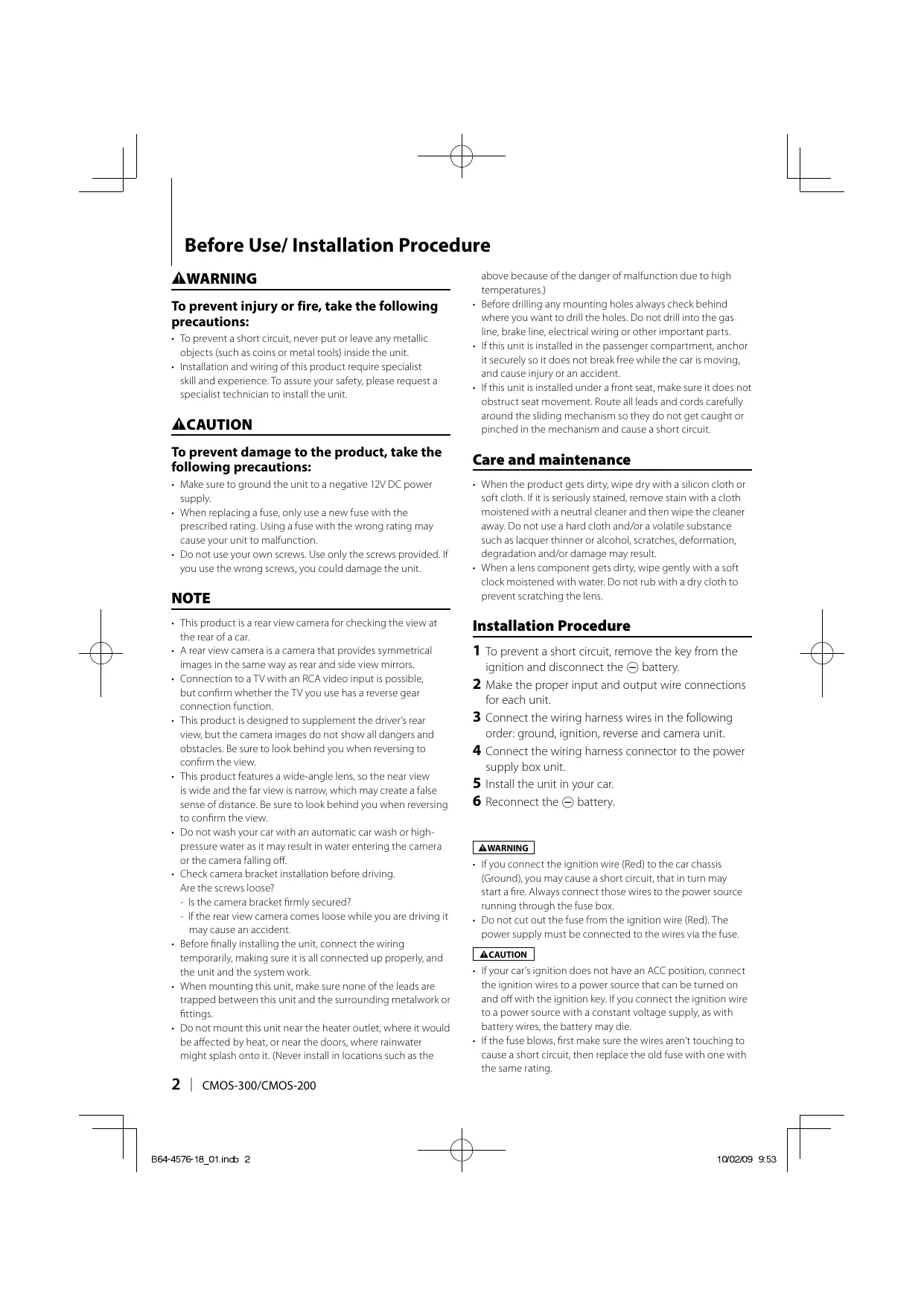
Before Use/ Installation Procedure
WARNING
To prevent injury or fire, take the following precautions:
- To prevent a short circuit, never put or leave any metallic objects (such as coins or metal tools) inside the unit.
- Installation and wiring of this product require specialist skill and experience. To assure your safety, please request a specialist technician to install the unit.
CAUTION
To prevent damage to the product, take the following precautions:
- Make sure to ground the unit to a negative 12V DC power supply.
- When replacing a fuse, only use a new fuse with the prescribed rating. Using a fuse with the wrong rating may cause your unit to malfunction.
- Do not use your own screws. Use only the screws provided. If you use the wrong screws, you could damage the unit.
NOTE
- This product is a rear view camera for checking the view at the rear of a car.
- A rear view camera is a camera that provides symmetrical images in the same way as rear and side view mirrors.
- Connection to a TV with an RCA video input is possible, but confirm whether the TV you use has a reverse gear connection function.
- This product is designed to supplement the driver's rear view, but the camera images do not show all dangers and obstacles. Be sure to look behind you when reversing to confirm the view.
- This product features a wide-angle lens, so the near view is wide and the far view is narrow, which may create a false sense of distance. Be sure to look behind you when reversing to confirm the view.
- Do not wash your car with an automatic car wash or high-pressure water as it may result in water entering the camera or the camera falling off.
- Check camera bracket installation before driving. Are the screws loose?
- Is the camera bracket firmly secured?
- If the rear view camera comes loose while you are driving it may cause an accident.
- Before finally installing the unit, connect the wiring temporarily, making sure it is all connected up properly, and the unit and the system work.
- When mounting this unit, make sure none of the leads are trapped between this unit and the surrounding metalwork or fittings.
- Do not mount this unit near the heater outlet, where it would be affected by heat, or near the doors, where rainwater might splash onto it. (Never install in locations such as the
above because of the danger of malfunction due to high temperatures.)
- Before drilling any mounting holes always check behind where you want to drill the holes. Do not drill into the gas line, brake line, electrical wiring or other important parts.
- If this unit is installed in the passenger compartment, anchor it securely so it does not break free while the car is moving, and cause injury or an accident.
- If this unit is installed under a front seat, make sure it does not obstruct seat movement. Route all leads and cords carefully around the sliding mechanism so they do not get caught or pinched in the mechanism and cause a short circuit.
Care and maintenance
- When the product gets dirty, wipe dry with a silicon cloth or soft cloth. If it is seriously stained, remove stain with a cloth moistened with a neutral cleaner and then wipe the cleaner away. Do not use a hard cloth and/or a volatile substance such as lacquer thinner or alcohol, scratches, deformation, degradation and/or damage may result.
- When a lens component gets dirty, wipe gently with a soft clock moistened with water. Do not rub with a dry cloth to prevent scratching the lens.
Installation Procedure
1 To prevent a short circuit, remove the key from the ignition and disconnect the ⊖ battery.
2 Make the proper input and output wire connections for each unit.
3 Connect the wiring harness wires in the following order: ground, ignition, reverse and camera unit.
4 Connect the wiring harness connector to the power supply box unit.
5 Install the unit in your car.
6 Reconnect the ⊖ battery.
▲WARNING
- If you connect the ignition wire (Red) to the car chassis (Ground), you may cause a short circuit, that in turn may start a fire. Always connect those wires to the power source running through the fuse box.
- Do not cut out the fuse from the ignition wire (Red). The power supply must be connected to the wires via the fuse.
CAUTION
- If your car's ignition does not have an ACC position, connect the ignition wires to a power source that can be turned on and off with the ignition key. If you connect the ignition wire to a power source with a constant voltage supply, as with battery wires, the battery may die.
-
If the fuse blows, first make sure the wires aren't touching to cause a short circuit, then replace the old fuse with one with the same rating.
-
Insulate unconnected wires with vinyl tape or other similar material. To prevent a short circuit, do not remove the caps on the ends of the unconnected wires or the terminals.
- After the unit is installed, check whether the brake lamps, blinkers, wipers, etc. on the car are working properly.
• Install so that it does not obstruct the rear field of view.
• Install so that it does not protrude from the side of the car. - Do not perform installation in rain or fog.
- When humidity is high, dry the surface to which the unit is to be attached before installing.
- Moisture on the attachment surface reduces adhesive strength, which may lead to the unit coming off.
- Do not attach the camera bracket to areas on the car body treated with fluorocarbon resin, or glass.
- May result in the rear view camera falling off.
- Do not apply water to the unit.
- Do not expose the unit to rain.
- Do not subject the camera to unnecessary force.
- Thoroughly clean where tape is used for sticking on the unit.
- Refer to the Instruction's manual for details on connecting the other units, then make connections correctly.
- Secure the wiring with cable clamps or adhesive tape. To protect the wiring, wrap adhesive tape around them where they lie against metal parts.
- Route and secure all wiring so it cannot touch any moving parts, such as the gear shift, handbrake and seat rails.
- Do not route wiring in places that get hot, such as near the heater outlet. If the insulation of the wiring melts or gets torn, there is a danger of the wiring short-circuiting to the vehicle body.
- When replacing the fuse, be sure to use only fuse of the rating prescribed on the fuse holder.
- To minimize noise locate the TV antenna cable, radio antenna cable and RCA cable as far away from each other as possible.
-
Do not install the power supply box unit in places where it may become subject to high temperatures or humidity, such as:
-
Places close to a heater, vent or air conditioner.
- Places exposed to direct sunlight, such as on top of the dashboard or the rear shelf.
- Places that may be splashed by rain, for example close to the door.
- Lay the cords by avoiding high-temperature areas. Use corrugated tubes for wiring inside the engine room. If a cord contacts a high-temperature area of the vehicle, the coating may melt and cause short-circuiting, which may lead to a fire or electric shock hazard.
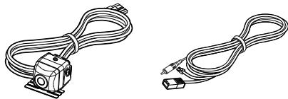
Accessories
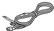
Camera (with camera bracket) ....1 Camera connection cord ....1
natural_image
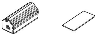
Two types of cable or wire connectors, one with a small sensor and the other with a plug (no text or symbols visible)Power supply box......1 Double-side adhesive tape (Large)......1
natural_image
Technical line drawing of a rectangular box and a flat rectangular plate (no text or symbols)Power cord .....1
natural_image
Line drawing of a coiled cable with connectors and connectors (no text or symbols)Waterproof packing ....1 Camera bracket clamping screw....1

natural_image
Simple line drawing of a 3D rectangular prism and a screw (no text or symbols)CMOS-300 only
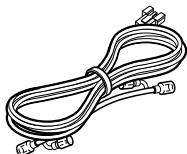
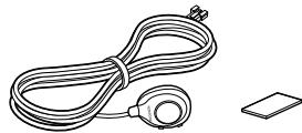
Switch unit......1 Double-side adhesive tape (Small) ......1

natural_image
Line drawing of a coiled cable with a connector and a separate flat surface (no text or symbols)Head unit connection cord .....1
natural_image
Line drawing of a coiled cable with connectors (no text or symbols)The head unit connection cord is used for connection to a Kenwood car navigation system equipped etc. with the camera control function.
Installation
CAUTION
- The adjustments during camera setting may be hindered depending on the camera installation position. Do not install the camera securely but attach it only temporarily until the camera setting has completed.
Recommended Installation Position
Examples of correct camera installation
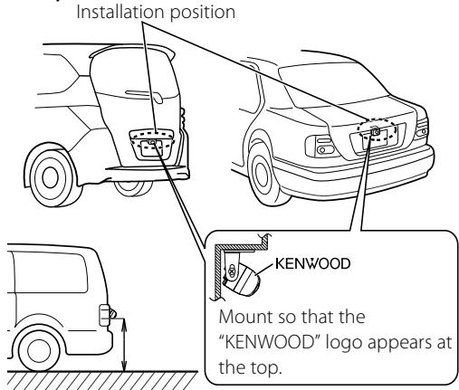
text_image
Installation position KENWOOD Mount so that the "KENWOOD" logo appears at the top.The CMOS-300 should be installed at a height of 55 cm (21.7 inch) or more.
Installing the Camera/Adjusting its angle
1 Decide the camera installation position.
2 Clean the camera installation surface.
Using a commercially available cleaner, wipe dirt, moisture and oil away from the surface on which the camera bracket is to be attached.
3 Loosen the camera bracket retaining screws.
Using a commercially available Phillips screwdriver, loosen the two retaining screws.
Perform steps 4 and 5 only when they are required.
4 If required, separate the camera bracket from the camera and adjust the shape according to the surface on which it will be attached.
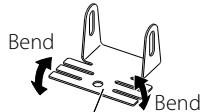
text_image
Bend BendCamera bracket
Adjust the camera bracket shape so that it fits the camera installation position.
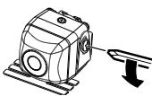
5 Mount the camera on the camera bracket.
Mount so that the "KENWOOD" logo appears at the top.
6 Fix the camera temporarily with tape, etc.
Using a piece of tape, etc., fix the camera temporarily and adjust the angles so that the rear end of the vehicle can be viewed.
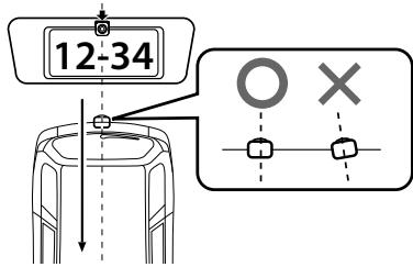
text_image
12-34 O XAttach the camera on the rear center position of the vehicle taking care not to hide the license plate. Make sure that the camera points straight toward the rear of the vehicle travel direction. Be careful not to lean the camera toward other directions of the vehicle, etc.
7 Complete all of the required connections.
8 Display the camera video.
Some video monitors may switch automatically to the external video input function. For details, read the instruction manual for your video monitor.
9 Change the shift lever to the R (Reverse) range to view the image of the rear of the vehicle.
Before viewing the camera, apply the parking brake and chock the wheels so that the vehicle will not move. Otherwise, an unexpected accident may result.
10 Adjust the camera angle so that the rear part of the vehicle or the rear bumper is visible at the bottom of the monitor screen.
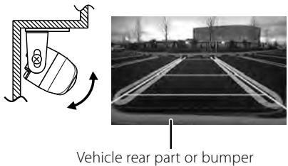
text_image
Vehicle rear part or bumperWhen adjusting the camera angle, be careful not to stretch the camera cord.
11 After adjusting the camera angle, tighten the retaining screws firmly.
Inspect the retaining screws at times. If they are loose, tighten them firmly.
12 Perform the operations in "Camera Setting" (page 8). (CMOS-300 only)
If an adjustment is not possible in the currently available range, change the camera position before retrying.
13 Fix the camera firmly in position.
Peel off the paper liner from the double-side adhesive tape on the camera bracket and attach it. After attaching, push the camera bracket with your finger to ensure close adhesion.
Do not touch the adhesive surface with your hand or peel and reattach an attached tape, as these will degrade the adhesive force and may cause the camera bracket to be detached. If required, secure the bracket on the vehicle body using the camera bracket clamping screw.
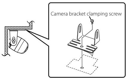
text_image
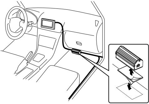
Camera bracket clamping screwInstalling the Power Supply Box
1 Attach double-side adhesive tape on the power supply box and then attach it under the carpet on the front passenger seat side.
natural_image
Interior view of a car dashboard and infotainment system (no text or symbols visible)Do not attach the power supply box in the following place.
- Place moistened by water.
- Unstable surface.
- Place that comes in the way of driving.
- Under high temperature.
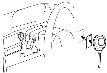
Installing the Switch Unit (CMOS-300 only)
1 Clean the switch unit installation surface.
Using a commercially available cleaner, wipe dirt, moisture and oil away from the surface on which the switch unit is to be attached.
2 Attach double-side adhesive tape on the bottom of the switch unit and then attach it in an easy-to-operate position, for example near the dashboard on the driver seat side.
natural_image
Line drawing of a car interior showing a valve and a close-up of a mounted device (no text or symbols)Connections
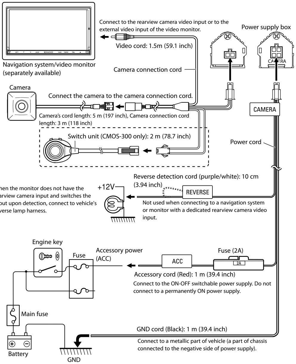
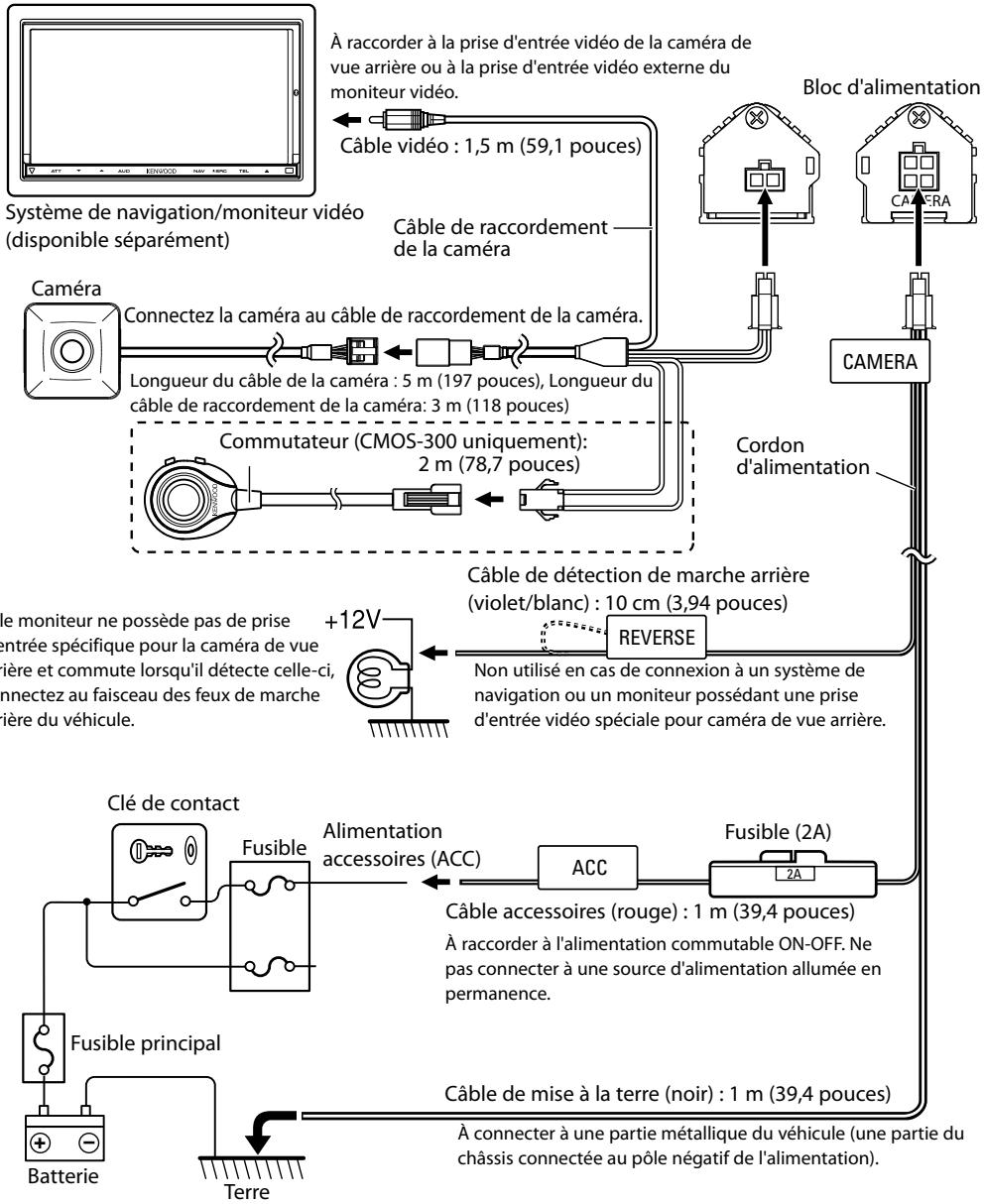
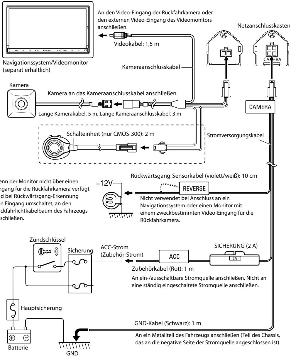
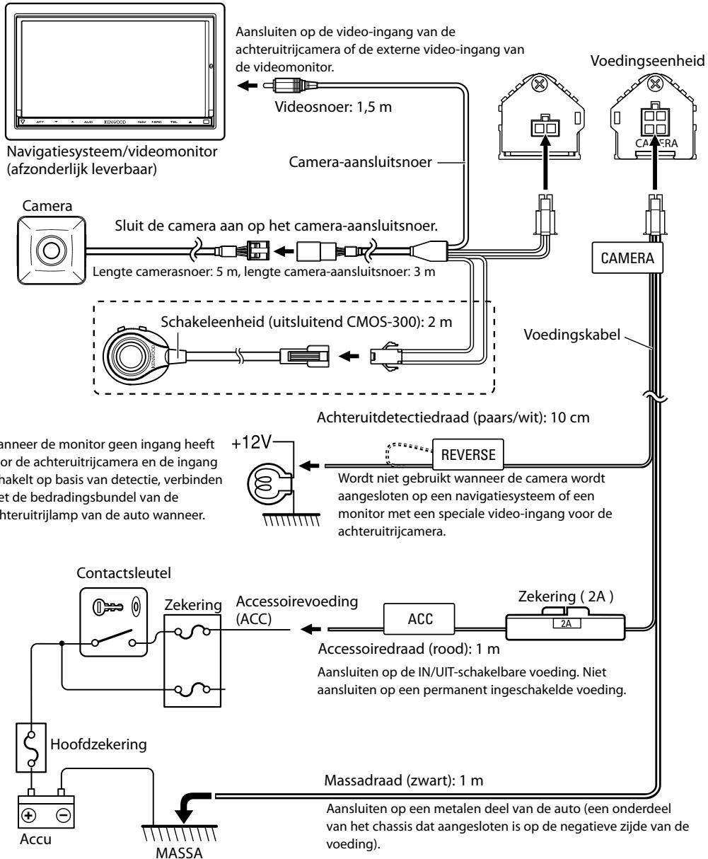
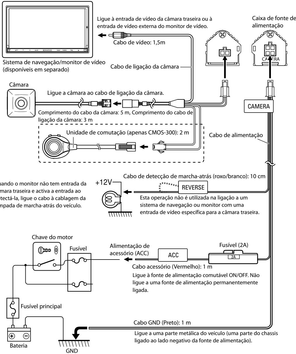
Basic Connections
flowchart
graph TD
    A["Camera"] -->|Connect to the camera to the camera connection cord.| B["Camera"]
    B --> C["Switch unit (CMOS-300 only): 2 m (78.7 inch)"]
    C --> D["Power supply box"]
    D --> E["POWER cord"]
    E --> F["Reverse detection cord (purple/white): 10 cm (3.94 inch)"]
    F --> G["Switch unit (CMOS-300 only): 2 m (78.7 inch)"]
    G --> H["Power cord"]
    H --> I["Power supply box"]
    I --> J["Power supply box"]
    J --> K["Power supply box"]
    K --> L["Power supply box"]
    L --> M["Power supply box"]
    M --> N["Power supply box"]
    N --> O["Power supply box"]
    O --> P["Power supply box"]
    P --> Q["Power supply box"]
    Q --> R["Power supply box"]
    R --> S["Power supply box"]
    S --> T["Power supply box"]
    T --> U["Power supply box"]
    U --> V["Power supply box"]
    V --> W["Power supply box"]
    W --> X["Power supply box"]
    X --> Y["Power supply box"]
    Y --> Z["Power supply box"]
    Z --> AA["Power supply box"]
    AA --> AB["Power supply box"]
    AB --> AC["Power supply box"]
    AC --> AD["Power supply box"]
    AD --> AE["Power supply box"]
    AE --> AF["Power supply box"]
    AF --> AG["Power supply box"]
    AG --> AH["Power supply box"]
    AH --> AI["Power supply box"]
    AI --> AJ["Power supply box"]
    AJ --> AK["Power supply box"]
    AK --> AL["Power supply box"]
    AL --> AM["Power supply box"]
    AM --> AN["Power supply box"]
    AN --> AO["Power supply box"]
    AO --> AP["Power supply box"]
    AP --> AQ["Power supply box"]
    AQ --> AR["Power supply box"]
    AR --> AS["Power supply box"]
    AS --> AT["Power supply box"]
    AT --> AU["Power supply box"]
    AU --> AV["Power supply box"]
    AV --> AW["Power supply box"]
    AW --> AX["Power supply box"]
    AX --> AY["Power supply box"]
    AY --> AZ["Power supply box"]
    AZ --> BA["Power supply box"]
    BA --> BB["Power supply box"]
    BB --> BC["Power supply box"]
    BC --> BD["Power supply box"]
    BD --> BE["Power supply box"]
    BE --> BF["Power supply box"]
    BF --> BG["Power supply box"]
    BG --> BH["Power supply box"]
    BH --> BI["Power supply box"]
    BI --> BJ["Power supply box"]
    BJ --> BK["Power supply box"]
    BK --> BL["Power supply box"]
    BL --> BM["Power supply box"]
    BM --> BN["Power supply box"]
    BN --> BO["Power supply box"]
    BO --> BP["Power supply box"]
    BP --> BQ["Power supply box"]
    BQ --> BR["Power supply box"]
    BR --> BS["Power supply box"]
    BS --> BT["Power supply box"]
    BT --> BU["Power supply box"]
    BU --> BV["Power supply box"]
    BV --> BW["Power supply box"]
    BW --> BX["Power supply box"]
    BX --> BY["Power supply box"]
    BY --> BZ["Power supply box"]
    BZ --> CA["Power supply box"]
    CA --> CB["Power supply box"]
    CB --> CC["Power supply box"]
    CC --> CD["Power supply box"]
    CD --> CE["Power supply box"]
    CE --> CF["Power supply box"]
    CF --> CG["Power supply box"]
    CG --> CH["Power supply box"]
    CH --> CI["Power supply box"]
    CI --> CJ["Power supply box"]
    CJ --> CK["Power supply box"]
    CK --> CR["Power supply box"]
    CR --> CS["Power supply box"]
    CS --> CT["Power supply box"]
    CT --> CU["Power supply box"]
    CU --> CV["Power supply box"]
    CV --> CW["Power supply box"]
    CW --> CX["Power supply box"]
    CX --> CY["Power supply box"]
    CY --> CZ["Power supply box"]
    CZ --> DA["Power supply box"]
    DA --> DB["Power supply box"]
    DB --> DC["Power supply box"]
    DC --> DD["Power supply box"]
    DD --> DE["Power supply box"]
    DE --> DF["Power supply box"]
    DF --> DG["Power supply box"]
    DG --> DH["Power supply box"]
    DH --> DI["Power supply box"]
    DI --> DJ["Power supply box"]
    DJ --> DK["Power supply box"]
    DK --> DL["Power supply box"]

CAUTION
- If the engine key of your vehicle does not have the ACC position, branch the wire energized when the engine key is ON and connect it to the accessory power cord.
- Before proceeding to connections, make sure that the engine key is not inserted and disconnect the () terminal of the battery to prevent the short-circuiting incident.
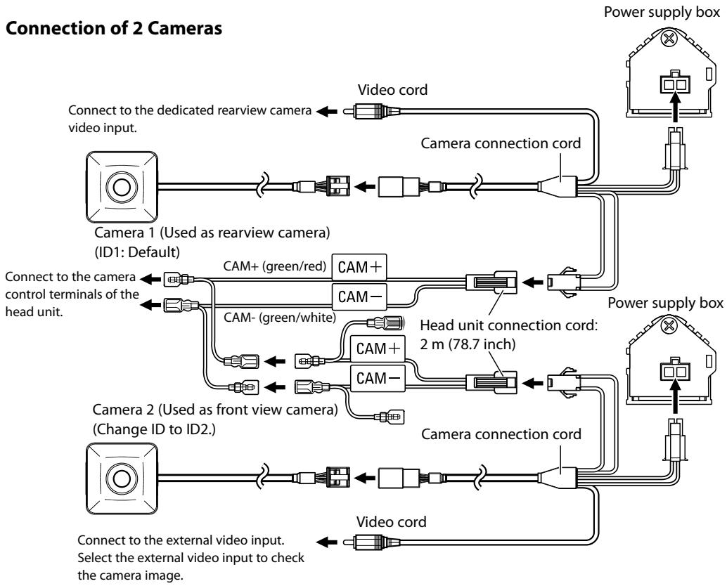
System Connection (CMOS-300 only)
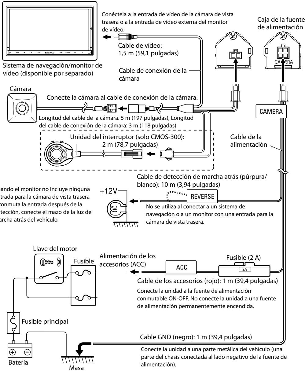
- When connecting the camera to a Kenwood navigation system (head unit) equipped with the camera control function, use the provided head unit connection cord. This allows the head unit to switch the display view and adjust the camera as well.
- When using two CMOS-300 units (for the front and rear), it is required to set an ID for the front camera. For details, see "Camera ID Setting" (page 13).
- Connect the power supply in the same way as "Basic Connections". The reverse detection cord (purple/white) is to be connected as required.
- The provided switch unit is not used in the system connection.
flowchart
graph TD
    A["Power supply box"] --> B["Camera 1 (Used as rearview camera)<br>(ID1: Default)"]
    B --> C["Connect to the dedicated rearview camera<br>video input"]
    B --> D["Video cord"]
    B --> E["Camera connection cord"]
    E --> F["Cam+ (green/red)"]
    E --> G["CAM-"]
    E --> H["Head unit connection cord:<br>2 m (78.7 inch)"]
    H --> I["Cam+"]
    H --> J["CAM-"]
    H --> K["Camera connection cord"]
    K --> L["Power supply box"]
    M["Camera 2 (Used as front view camera)<br>(Change ID to ID2.)"] --> N["Connect to the external video input.<br>Select the external video input to check the camera image."]
    N --> O["Video cord"]
    N --> P["Video cord"]
    Q["Cam- (green/white)"] --> R["Cam+"]
    Q --> S["CAM-"]
Camera Setting (CMOS-300 only)
Switch Unit Operation
The switch unit can be used to switch the image display mode, view/hide the guideline display and adjust the camera.
View button
- Switches the image display mode.
- Select an item in the setting mode.
- Press and hold to display or hide the guidelines.
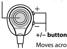
text_image
MENWOOD +/- button Moves acrossMoves across the setting mode items or sets an adjustment value.
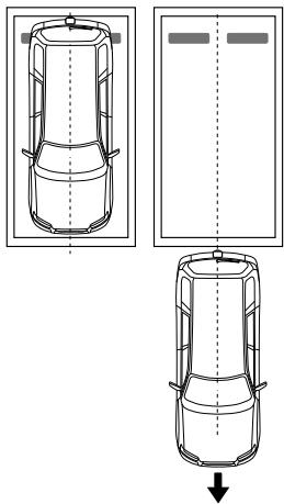
Preparation Before Camera Setting
1 Stop the vehicle.
In a parking space with white lines and tire stoppers, park the vehicle in the center of the white line frame.
2 Advance the vehicle.
- Move the vehicle forward until the entire parking space can be viewed in the camera image.
- Be sure to apply the parking brake and push the brake pedal so that the vehicle is completely stationary. Perform the setting in a place that will not cause nuisance to other people.
natural_image
Top-down line drawing of a car showing front, side, and side views with no text or symbolsCamera Setting Procedure
1 Complete all of the required connections in advance.
2 Display the camera video.
Some video monitors may switch automatically to the external video input function. For details, read the instruction manual for your video monitor.
3 Press and hold the view and + buttons of the switch unit simultaneously to enter the camera adjustment mode.
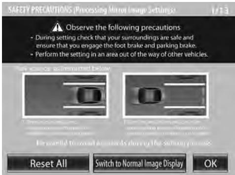
4 First select the positioning of the camera.
text_image
SAFETY PRECAUTIONS (Processing Mirror Image Settings) 1/13 Observe the following precautions - During setting check that your surroundings are safe and ensure that you engage the foot brake and parking brake. - Perform the setting in an area out of the way of other vehicles. Please use an unremacted below Reset All Switch to Normal Image Display OKUse the + or – button to select an item and press the view button to enter the selection.
- When using the camera as the rearview camera, select [OK].
- When using the camera as the front camera, select [Switch to Normal Image Display] and then select [OK].
- Selecting [Reset All] resets all of the camera settings to the defaults.
5 Select a camera adjustment item and adjust it.
The following items are available for camera adjustment.
- Overhead view image adjustments
(Centering, Right-and-Left angle, Up-and-Down Angle) - Wide view guideline adjustments (Size, Horizontal direction, Vertical direction, Red Line Position Setting)
- Overhead guideline adjustments (Size, Horizontal direction, Vertical direction, Red Line Position Setting)
To select an item:
Press the + or – button to select an item and press the view button to enter the selection. When an adjustment item is selected, the frame of its icon turns from blue to red.
To adjust the item:
After selecting the item, press the + or - button to adjust it and press the view button to enter the adjusted value.
6 End the setting.
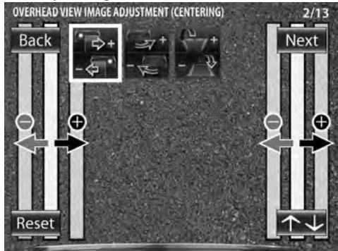
Overhead View Image Adjustment (Centering)
This item adjusts the center of the camera installation position.
1 Select "OVERHEAD VIEW IMAGE ADJUSTMENT (CENTERING)".
2 Press the + or - button of the switch unit so that the two white lines appear on the position corresponding to the center line of the vehicle.
flowchart
graph TD
    A["Back"] --> B["+"]
    C["Reset"] --> D["-"]
    E["Next"] --> F["+"]
    G["Forward Icon"] --> H["+"]
    I["Arrow Left"] --> J["+"]
    K["Arrow Right"] --> L["+"]
    M["Arrow Down"] --> N["+"]
    O["Arrow Up"] --> P["+"]
    Q["Arrow Down"] --> R["+"]
    S["Arrow Up"] --> T["+"]
    U["Arrow Down"] --> V["+"]
    W["Arrow Up"] --> X["+"]
    Y["Arrow Down"] --> Z["+"]
    AA["Arrow Up"] --> AB["+"]
    AC["Arrow Down"] --> AD["+"]
    AE["Arrow Up"] --> AF["+"]
    AG["Arrow Down"] --> AH["+"]
    AI["Arrow Up"] --> AJ["+"]
    AK["Arrow Down"] --> AL["+"]
    AM["Arrow Up"] --> AN["+"]
    AO["Arrow Down"] --> AP["+"]
    AQ["Arrow Up"] --> AR["+"]
    AS["Arrow Down"] --> AT["+"]
Adjustment is possible by one step to the left and right. If the adjustment is not possible in the currently available range, change the camera position before retry.
- Select [Back] to go back to the previous adjustment item.
- Select [Next] to advance to the next adjustment item.
- Selecting [Reset] in an individual adjustment item resets the camera setting of that item to the default.
- Select [↑↓] to invert the icon upside down.
3 After completing the adjustment, press the view button.
↓ Advances to "OVERHEAD VIEW IMAGE ADJUSTMENT (Right-and-Left ANGLE)".
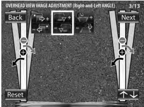
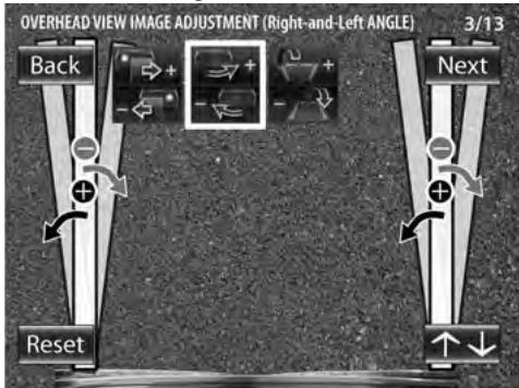
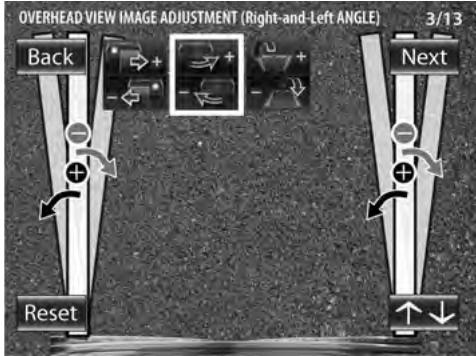
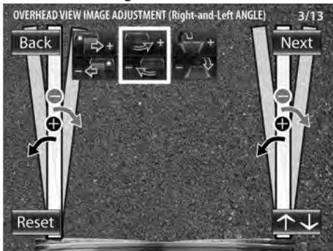
Overhead View Image Adjustment (Right-and-Left Angle)
This item adjusts the horizontal angle (in the rotary direction) of the camera installation position.
1 Select "OVERHEAD VIEW IMAGE ADJUSTMENT (Right-and-Left ANGLE)".
text_image
OVERHEAD VIEW IMAGE ADJUSTMENT (Right-and-Left ANGLE) 3/13 Back Next Reset2 Press the + or - button of the switch unit so that the center of the parking space is displayed vertically.
Adjustment is possible by one step to the left and right. If the adjustment is not possible in the currently available range, change the camera position before retrying.
3 After completing the adjustment, press the view button.
↓ Advances to "OVERHEAD VIEW IMAGE ADJUSTMENT (Up-and-Down ANGLE)".
Camera Setting (CMOS-300 only)
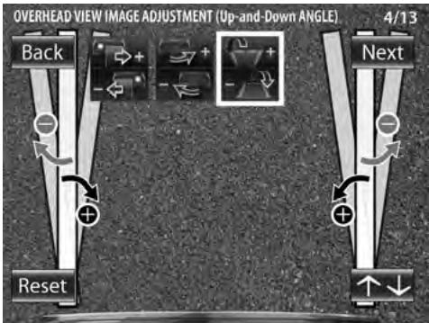
Overhead View Image Adjustment (Up-and-Down Angle)
This item adjusts the vertical angle (inclination) of the camera installation position.
1 Select "OVERHEAD VIEW IMAGE ADJUSTMENT (Up-and-Down ANGLE)".
2 Press the + or - button of the switch unit so that the lines indicating the vehicle width are shown vertical.
text_image
OVERHEAD VIEW IMAGE ADJUSTMENT (Up-and-Down ANGLE) 4/13 Back Reset NextAdjustment is possible by one step up and down. If the adjustment is not possible in the currently available range, change the camera position before retrying.
3 After completing the adjustment, press the view button.
4 Select [Next].
↓ Advances to "WIDE VIEW GUIDELINE ADJUSTMENT (Size)".
For Guideline Adjustment
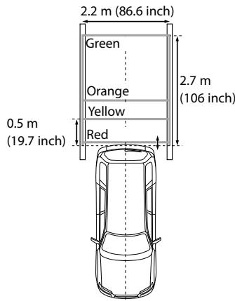
• The subsequent adjustments adjust the sizes, lengths and positions of the guidelines displayed in the wide view and overhead view. By default, three guidelines shown below (green, yellow and red) are displayed assuming that the camera installation height is 80 cm (31.5 inch) and that the distance between the left and right lines of the parking space is 2.2 meters (86.6 inch). Adjusting the wide view or overhead guidelines alters the interval between the corresponding guidelines. As the interval between each set of guidelines varies depending on the camera installation height, check the actual settings after all of the following adjustments are completed.
- Once the interval between guidelines has been adjusted according to your parking space, the displayed guidelines do no longer indicate the width of the vehicle. Note that the sizes of parking space are greatly variable and confirm the actual size of each parking space before attempting to park in it.
- The subsequent adjustments adjust the sizes, lengths and positions of the guidelines displayed in the wide view and overhead view. By default, three guidelines shown below (green, yellow and red) are displayed assuming that the camera installation height is 80~cm (31.5 inch) and that the distance between the left and right lines of the parking space is 2.2 meters (86.6 inch). Adjusting the wide view or overhead guidelines alters the interval between the corresponding guidelines. As the interval between each set of guidelines varies depending on the camera installation height, check the actual settings after all of the following adjustments are completed. - Once the interval between guidelines has been adjusted according to your parking space, the displayed guidelines do no longer indicate the width of the vehicle. Note that the sizes of parking space are greatly variable and confirm the actual size of each parking space before attempting to park in it.
• The orange line indicates the position of the overhead view (area on the near side of the orange line) and of the wide view (area beyond the orange line) in the PinP view (page 14). When the orange line displayed in the wide view exceeds the parking line, slow down the vehicle and move until the red line (parking position) by checking it in the overhead view.
- The red line is used to indicate the parking position and can set it independently from other guide lines.
- The orange line indicates the position of the overhead view (area on the near side of the orange line) and of the wide view (area beyond the orange line) in the PinP view (page 14). When the orange line displayed in the wide view exceeds the parking line, slow down the vehicle and move until the red line (parking position) by checking it in the overhead view. - The red line is used to indicate the parking position and can set it independently from other guide lines.
text_image
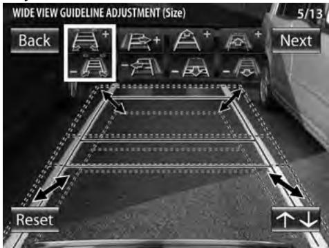
2.2 m (86.6 inch) Green Orange Yellow Red 0.5 m (19.7 inch) 2.7 m (106 inch)Wide View Guideline Adjustment (Size)
This item adjusts the overall size of guidelines displayed in the wide view.
1 Select "WIDE VIEW GUIDELINE ADJUSTMENT (Size)".
2 Press the + or - button of the switch unit to adjust the size.
text_image
WIDE VIEW GUIDELINE ADJUSTMENT (Size) 5/13 Back + - + + - + - Next Reset ↑↓3 After completing the adjustment, press the view button.
↓ Advances to "WIDE VIEW GUIDELINE ADJUSTMENT (Horizontal direction)".
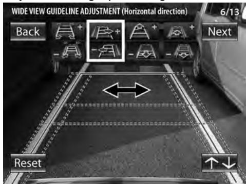
Wide View Guideline Adjustment (Horizontal Direction)
This item adjusts the left-right positioning of the guidelines displayed in the wide view.
1 Select "WIDE VIEW GUIDELINE ADJUSTMENT (Horizontal direction)".
2 Press the + or - button of the switch unit to adjust the left-right positioning.
text_image
WIDE VIEW GUIDELINE ADJUSTMENT (Horizontal direction) Back Next Reset 6/133 After completing the adjustment, press the view button.
Advances to "WIDE VIEW GUIDELINE ADJUSTMENT (Vertical direction)".
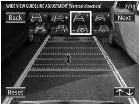
Wide View Guideline Adjustment (Vertical Direction)
This item adjusts the length of the guidelines displayed in the wide view.
1 Select "WIDE VIEW GUIDELINE ADJUSTMENT (Vertical direction)".
2 Press the + or - button of the switch unit to adjust the length.
text_image
WIDE VIEW GUIDELINE ADJUSTMENT (Vertical direction) Back Next Reset3 After completing the adjustment, press the view button.
↓ Advances to "WIDE VIEW GUIDELINE ADJUSTMENT (Red Line Position Setting)."
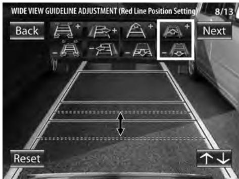
Wide View Guideline Adjustment (Red Line Position Setting)
This item adjusts the position of the red line displayed in the wide view. The red line can be used independently to set the reference line for the vehicle parking position.
1 Select "WIDE VIEW GUIDELINE ADJUSTMENT (Red Line Position Setting)".
2 Press the + or - button of the switch unit to adjust the position of the red line.
By default, the red line is superimposed with the yellow line that is closest to the vehicle. Move the red line until the edge of your vehicle's bumper.
text_image
WIDE VIEW GUIDELINE ADJUSTMENT (Red Line Position Setting) 8/13 Back + + + + + - - - - - - - - - - - - - - - - - - - - - - - - - - - - - - - - - - - - - - - - - - - - - - - - - - - - - - - - - - - - - - - - - - - - - - - - - - - - - - - - - - - - - -3 After completing the adjustment, press the view button.
4 Select [Next].
↓ Advances to "OVERHEAD VIEW GUIDELINE ADJUSTMENT (Size)".
Camera Setting (CMOS-300 only)
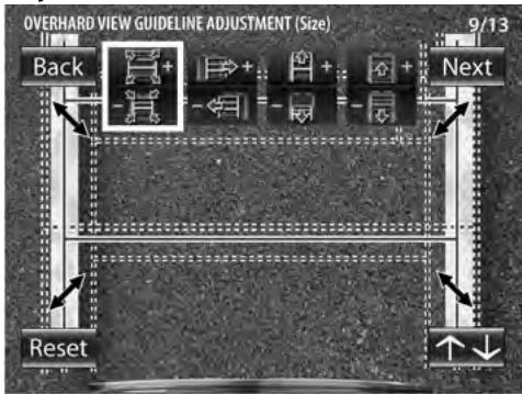
Overhead View Guideline Adjustment (Size)
This item adjusts the overall size of the guidelines displayed in the overhead view.
1 Select "OVERHEAD VIEW GUIDELINE ADJUSTMENT (Size)".
2 Press the + or - button of the switch unit to adjust the size.
flowchart
graph TD
    A["Back"] --> B["+"]
    B --> C["+"]
    C --> D["+"]
    D --> E["Next"]
    F["Reset"] --> G["↑"]
    H["9/13"] --> I["↓"]
3 After completing the adjustment, press the view button.
↓ Advances to "OVERHEAD VIEW GUIDELINE ADJUSTMENT (Horizontal direction)".
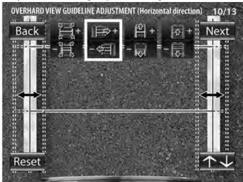
Overhead View Guideline Adjustment (Horizontal Direction)
This item adjusts the left-right positioning of the guidelines displayed in the overhead view.
1 Select "OVERHEAD VIEW GUIDELINE ADJUSTMENT (Horizontal direction)".
2 Press the + or - button of the switch unit to adjust the left-right positioning.
flowchart
graph TD
    A["Back"] --> B["+"]
    B --> C["→"]
    C --> D["+"]
    D --> E["→"]
    E --> F["Next"]
    G["Reset"] --> H["↓"]
    I["10/13"] --> J["↑"]
3 After completing the adjustment, press the view button.
↓ Advances to "OVERHEAD VIEW GUIDELINE ADJUSTMENT (Vertical direction)".
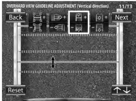
Overhead View Guideline Adjustment (Vertical Direction)
This item adjusts the overall length of the guidelines displayed in the overhead view.
1 Select "OVERHEAD VIEW GUIDELINE ADJUSTMENT (Vertical direction)".
2 Press the + or - button of the switch unit to adjust the length.
text_image
OVERHARD VIEW GUIDELINE ADJUSTMENT (Vertical direction) 11/13 Back + + + + Next Reset ↑↓3 After completing the adjustment, press the view button.
Advances to "OVERHEAD VIEW GUIDELINE ADJUSTMENT (Red Line Position Setting)".
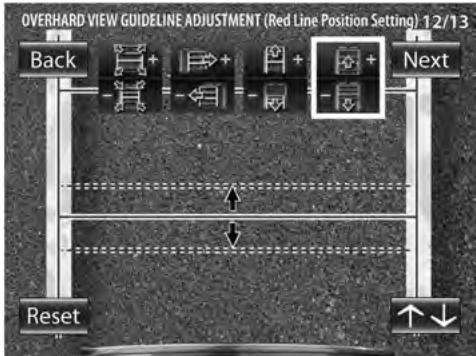
Overhead View Guideline Adjustment (Red Line Position Setting)
This item adjusts the position of the red line displayed in the overhead view. The red line can be used independently to set the reference line for the vehicle parking position.
1 Select "OVERHEAD VIEW GUIDELINE ADJUSTMENT (Red Line Position Setting)".
2 Press the + or - button of the switch unit to adjust the position of the red line.
By default, the red line is superimposed with the yellow line that is closest to the vehicle. Move the red line until the edge of your vehicle's bumper.
flowchart
graph TD
    A["Back"] --> B["+"]
    B --> C["→"]
    C --> D["+"]
    D --> E["→"]
    E --> F["Next"]
    G["Reset"] --> H["↑"]
    I["↑↓"] --> J["←"]
3 After completing the adjustment, press the view button.
4 Select [Next].

Advances to "SETTING COMPLETE".
Finishing the Camera Setting
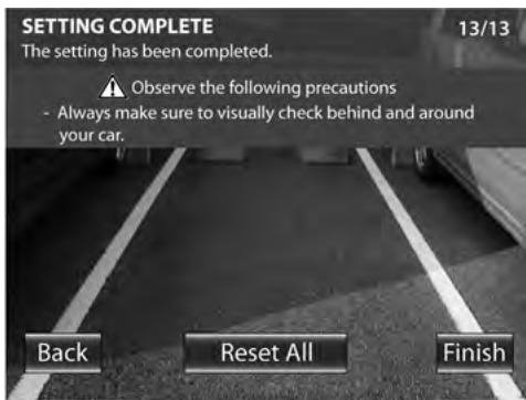
text_image
SETTING COMPLETE The setting has been completed. ▲ Observe the following precautions - Always make sure to visually check behind and around your car. Back Reset All Finish 13/131 Press the + or - button of the switch unit to select [Finish] and press the view button.
Camera ID Setting
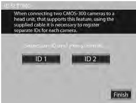
When connecting two CMOS-300 units to a Kenwood navigation system equipped etc. with the camera control function, it is required to assign different camera IDs to the 2 cameras. The camera IDs of both cameras have been set to ID1 at the factory.
1 Press and hold the + button of the switch unit for more than 2 seconds, and then press and hold the - button for more than 2 seconds.
2 Press the + or - button of the switch unit to select the camera ID, and press the view button.
text_image
When connecting two CMOS-300 cameras to a head unit, that supports this feature, using the supplied cable it is necessary to register separate IDs for each camera. ID 1 ID 2 Finish3 After setting, press the + or - button of the switch unit to select [Finish] and press the view button.
Display View Switching (CMOS-300 only)
Display View Switching
The CMOS-300 camera system can display 5 kinds of camera images.
1 With an image displayed on the monitor, press the view button of the switch unit.
Each press switches the image display mode in the following order.
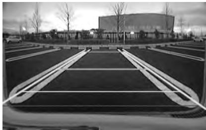
Super Wide View
Wide-angle image covering a horizontal angle of about 190^ .
natural_image
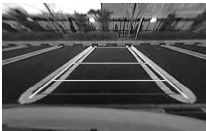
Exterior view of a modern parking lot with lanes and a large building in the background (no signage or text visible)Wide View
Camera image covering a horizontal angle of about 135^ .
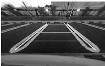
natural_image
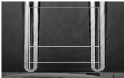
Black and white photo of a parking lot with lanes and windows, no visible text or symbolsOverhead View
Image seen from the viewpoint straight up above the vehicle.
natural_image
Close-up of a U-shaped metal frame with horizontal lines, against a dark background (no text or symbols)PinP View
The overhead view is displayed on the upper half of the screen while the wide view is displayed on the lower half. The overhead view in the upper half of the screen shows the area on the nearer side of the orange line shown in the wide view in the lower half.
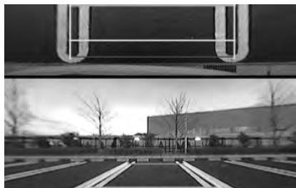
natural_image
Black-and-white exterior view of a modern building with visible windows and bare trees, no text or symbols present.Corner View
The views seen from the two corners of vehicle are displayed on the left and right halves of the screen.
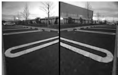
natural_image
Exterior view of a parking lot with curved parking markings and a modern building in the background (no signage or text visible)Specifications
Camera Unit (CMOS-300)
Output video
: Wide-angle mirror image (for rearview)/wide-angle normal image (for front view)
Sensor: 1/4-inch color CMOS sensor
Number of pixels: Approx. 310,000 pixels
Lens
: Wide angle, focal length f=0.82mm, F value 2.6
Angles of view
: Horizontal: Approx. 190°
: Vertical: Approx. 158°
Illumination range
: Approx. 0.9 to 100,000 lux
Iris system: Electronic iris
Scanning system: Interlace
Synchronizing system: Internal synchronization
Video output: 1Vp-p/75Ω
Dimensions (WxHxD): 24 x 24 x 24.8 mm
Weight: Approx. 30 g (without cable)
Camera Unit (CMOS-200)
Output video
: Wide-angle mirror image (for rearview)
Sensor: 1/4-inch color CMOS sensor
Number of pixels: Approx. 310,000 pixels
Lens
: Wide angle, focal length f=1.6mm, F value 2.3
Angles of view
: Horizontal: Approx. 135°
: Vertical: Approx. 105°
Illumination range
: Approx. 0.9 to 100,000 lux
Iris system: Electronic iris
Scanning system: Interlace
Synchronizing system: Internal synchronization
Video output: 1Vp-p/75Ω
Dimensions (WxHxD): 24 x 24 x 24.8 mm
Weight: Approx. 29 g (without cable)
Switch Unit (CMOS-300 only)
Dimensions (WxHxD): 27.5 x 32.8 x 12 mm
Weight: Approx. 10 g (without cable)
Power Supply Box Unit
Operating voltage
: 14.4V (11V - 16V)
Max. current consumption (CMOS-300)
: 150mA
Max. current consumption (CMOS-200)
: 100mA
Dimensions (WxHxD): 54 x 23 x 22 mm
Weight: Approx. 32 g
- Mirror image means that the video image inverts the left and right just like the image seen on the rearview mirror or a side mirror.
- Specifications subject to change without notice.

This symbol mark indicates that Kenwood manufactured this product so as to decrease harmful influence on the environment.
This Product is not installed by the manufacturer of a vehicle on the production line, nor by the professional importer of a vehicle into an EU Member State.
Information on Disposal of Old Electrical and Electronic Equipment and Batteries (applicable for EU countries that have adopted separate waste collection systems)

Products and batteries with the symbol (crossed-out wheeled bin) cannot be disposed as household waste.
Old electrical and electronic equipment and batteries should be recycled at a facility capable of handling these items and their waste byproducts.

Contact your local authority for details in locating a recycle facility nearest to you.
Proper recycling and waste disposal will help conserve resources whilst preventing detrimental effects on our health and the environment.
Notice: The sign "Pb" below the symbol for batteries indicates that this battery contains lead.
For Turkey
This product complies with Directive, Number 26891 regarding "REGULATION ON THE RESTRICTION OF THE USE OF CERTAIN HAZARDOUS SUBSTANCES IN ELECTRICAL AND ELECTRONIC EQUIPMENT".
natural_image
Two types of cable connectors shown in line drawings, no text or symbols presentnatural_image
Technical line drawing of a rectangular housing and a flat rectangular block (no text or symbols)Cordon d'alimentation .....1

natural_image
Line drawing of a coiled cable with connectors and connectors (no text or symbols)natural_image
Technical line drawing of a saw and a screw (no text or symbols)CMOS-300 uniquement
Commutateur......1
Ruban adhésif double face (petit format) .....1
natural_image
Illustration of a coiled cable with a connector and a separate flat plate (no text or symbols)natural_image
Line drawing of a coiled cable with connectors (no text or symbols)text_image
12:34 O Xnatural_image
Interior view of a car dashboard with steering wheel, dashboard panel, and cable connector (no text or symbols)natural_image
Line drawing of a car interior showing a switch and battery, with a close-up of the battery plug (no text or symbols)Raccordements
Raccordements de base
natural_image
Top-down line drawing of a car showing front, side, and side views with no text or symbolstext_image
SAFETY PRECAUTIONS (Processing Mirror Image Settings) 1/13 Observe the following precautions - During setting check that your surroundings are safe and ensure that you engage the foot brake and parking brake. - Perform the setting in an area out of the way of other vehicles. Reset All Switch to Normal Image Display OKtext_image
OVERHEAD VIEW IMAGE ADJUSTMENT (Right-and-Left ANGLE) 3/13 Back Next Resettext_image
OVERHEAD VIEW IMAGE ADJUSTMENT (Up-and-Down ANGLE) 4/13 Back Next Resettext_image
WIDE VIEW GUIDELINE ADJUSTMENT (Size) 5/13 Back Next Resettext_image
WIDE VIEW GUIDELINE ADJUSTMENT (Horizontal direction) Back Next Reset 6/13text_image
WIDE VIEW GUIDELINE ADJUSTMENT (Vertical direction) Back Next Resettext_image
WIDE VIEW GUIDELINE ADJUSTMENT (Red Line Position Setting) 8/13 Back Next ResetPage suivante ▶
text_image
OVERHARD VIEW GUIDELINE ADJUSTMENT (Horizontal direction) 10/13 Back + + + + + Next Reset ↑↓text_image
SETTING COMPLETE The setting has been completed. ▲ Observe the following precautions - Always make sure to visually check behind and around your car. Back Reset All Finish 13/13text_image
When connecting two CMOS-300 cameras to a head unit, that supports this feature, using the supplied cable it is necessary to register separate IDs for each camera. ID 1 ID 2 Finishnatural_image
Exterior view of a modern parking lot with curved parking areas and a large building in the background (no signage or text visible)Grand angle
Image couvrant un angle horizontal d'environ 135°.
natural_image
Black and white photo of a paved road with lane markings and overhead structures (no visible text or symbols)Vue de dessus
natural_image
Close-up of a U-shaped metal frame with vertical lines, against a dark background (no text or symbols)Vue PinP
natural_image
Black-and-white exterior view of a modern building with visible windows and bare trees, no text or symbols present.Vue d'angle
natural_image
Exterior view of a parking lot with curved parking markings and parked cars (no signage or text visible)Caméra (CMOS-300)
Vidéo en sortie
Dimensions (L x H x P): 54 x 23 x 22 mm
Poids: environ 32 g
natural_image
Two types of cable or connector packages, one with a small sensor and the other with a plug (no text or symbols visible)natural_image
Technical line drawing of a rectangular housing with a flat roof and a flat base (no text or symbols)Stromversorgungskabel .....1
natural_image
Line drawing of a coiled cable with connectors and connectors (no text or symbols)natural_image
Simple line drawing of a 3D rectangular prism and a screw (no text or symbols)nur CMOS-300
natural_image
Line drawing of a coiled cable with a connector and a separate flat surface (no text or symbols)natural_image
Line drawing of a coiled cable with connectors (no text or symbols)text_image
12:34 O Xnatural_image
Two black-and-white photos: one showing a mounted security camera with rotation arrow, the other showing a large outdoor track with buildings in the background (no text or symbols)natural_image
Interior view of a car dashboard and infotainment system (no text or symbols visible)natural_image
Line drawing of a car interior showing steering wheel and dashboard, with a close-up of the dashboard panel (no text or symbols)Anschlüsse
Grundanschlüsse
natural_image
Top-down diagram of a car showing front, side, and side views with no text or symbolstext_image
SAFETY PRECAUTIONS (Processing Mirror Image Setup) 1/13 Observe the following precautions - During setting check that your surroundings are safe and ensure that you engage the foot brake and parking brake. - Perform the setting in an area out of the way of other vehicles. Please use all instructions below Reset All Switch to Normal Image Display OKflowchart
graph TD
    A["Back"] --> B["+"]
    C["Reset"] --> D["-"]
    E["Next"] --> F["+"]
    G["Arrow Up"] --> H["Downward Arrow"]
    I["Arrow Down"] --> J["Upward Arrow"]
    K["Arrow Left"] --> L["Downward Arrow"]
    M["Arrow Right"] --> N["Downward Arrow"]
    O["Arrow Left"] --> P["Downward Arrow"]
    Q["Arrow Right"] --> R["Downward Arrow"]
    S["Arrow Left"] --> T["Downward Arrow"]
    U["Arrow Right"] --> V["Downward Arrow"]
    W["Arrow Left"] --> X["Downward Arrow"]
    Y["Arrow Right"] --> Z["Downward Arrow"]
    AA["Arrow Left"] --> AB["Downward Arrow"]
    AC["Arrow Right"] --> AD["Downward Arrow"]
    AE["Arrow Left"] --> AF["Downward Arrow"]
    AG["Arrow Right"] --> AH["Downward Arrow"]
    AI["Arrow Left"] --> AJ["Downward Arrow"]
    AK["Arrow Right"] --> AL["Downward Arrow"]
    AM["Arrow Left"] --> AN["Downward Arrow"]
    AO["Arrow Right"] --> AP["Downward Arrow"]
    AQ["Arrow Left"] --> AR["Downward Arrow"]
    AS["Arrow Right"] --> AT["Downward Arrow"]
    AU["Arrow Left"] --> AV["Downward Arrow"]
    AW["Arrow Right"] --> AX["Downward Arrow"]
    AY["2/13"] --> Z
text_image
OVERHEAD VIEW IMAGE ADJUSTMENT (Right-and-Left ANGLE) 3/13 Back Next Resettext_image
OVERHEAD VIEW IMAGE ADJUSTMENT (Up-and-Down ANGLE) 4/13 Back Next Resettext_image
WIDE VIEW GUIDELINE ADJUSTMENT (Size) 5/13 Back Next Resettext_image
WIDE VIEW GUIDELINE ADJUSTMENT (Horizontal direction) Back Next Resettext_image
WIDE VIEW GUIDELINE ADJUSTMENT (Vertical direction) Back Next Resettext_image
WIDE VIEW GUIDELINE ADJUSTMENT (Red Line Position Setting) 8/13 Back + + + + - - - - - - - - Next Reset ↑↓Nächste Seite
text_image
OVERHARD VIEW GUIDELINE ADJUSTMENT (Horizontal direction) 10/13 Back + + + + + Next Reset ↑↓text_image
OVERHARD VIEW GUIDELINE ADJUSTMENT (Red Line Position Setting) 12/13 Back + - + - + - Next Reset ↑↓text_image
SETTING COMPLETE The setting has been completed. ▲ Observe the following precautions - Always make sure to visually check behind and around your car. Back Reset All Finish 13/13text_image
When connecting two CMOS-300 cameras to a head unit, that supports this feature, using the supplied cable it is necessary to register separate IDs for each camera. ID 1 ID 2 Finishnatural_image
Exterior view of a modern parking lot with curved parking areas and a large building in the background (no signage or text visible)Weite Ansicht
natural_image
Exterior view of a parking lot with lanes and overhead lighting (no signage or text visible)Über-Kopf-Ansicht
natural_image
Close-up of a U-shaped metal frame with horizontal lines, against a dark background (no text or symbols)PinP-Ansicht
natural_image
Black-and-white exterior view of a modern building with visible windows and bare trees, no text or symbols present.Eckansicht
natural_image
Exterior view of a parking lot with curved parking markings and a modern building in the background (no signage or text visible)Technische Daten
Kamera (CMOS-300)
Video-Ausgang
natural_image
Two types of cable connectors shown in line drawing style, no text or symbols presentVoedingseenheid......1
natural_image
Technical line drawing of a rectangular housing with a side panel, no text or symbols presentnatural_image
Line drawing of a coiled cable with connectors and connectors (no text or symbols)Waterdichte behuizing......1
Klemschroef camerabeugel......1

natural_image
Technical drawing of a saw and a screw (no text or symbols)natural_image
Line drawing of a coiled cable with a connector and a separate flat surface (no text or symbols)natural_image
Line drawing of a coiled cable with connectors (no text or symbols)natural_image
Two black-and-white photos: one showing a mounted security camera with rotation arrow, the other showing a large outdoor track with buildings in the background (no text or symbols)natural_image
Interior view of a car dashboard with cable and control panel, showing a close-up of the cable being inserted (no text or symbols visible)natural_image
Line drawing of a car interior showing steering wheel and dashboard (no text or symbols)Aansluitingen
Basisaansluitingen
natural_image
Top-down diagram of a car showing front, side, and side views with no text or symbolsCamera-instellingsprocedure
text_image
SAFETY PRECAUTIONS (Processing Mirror Image Setup) 1/13 Observe the following precautions - During setting check that your surroundings are safe and ensure that you engage the foot brake and parking brake. - Perform the setting in an area out of the way of other vehicles. Reset All Switch to Normal Image Display OK1 Selecteer "OVERHEAD VIEW IMAGE ADJUSTMENT (Right-and-Left ANGLE)".

text_image
OVERHEAD VIEW IMAGE ADJUSTMENT (Right-and-Left ANGLE) 3/13 Back Next Resettext_image
WIDE VIEW GUIDELINE ADJUSTMENT (Size) 5/13 Back Next Resettext_image
WIDE VIEW GUIDELINE ADJUSTMENT (Horizontal direction) Back Next Reset 6/13text_image
WIDE VIEW GUIDELINE ADJUSTMENT (Vertical direction) Back Next Resettext_image
WIDE VIEW GUIDELINE ADJUSTMENT (Red Line Position Setting) 8/13 Back + + + + - - - - - - - - Next Reset ↑↓Volgende pagina ▶
text_image
OVERHARD VIEW GUIDELINE ADJUSTMENT (Horizontal direction) 10/13 Back + + + + + Next Resettext_image
OVERHARD VIEW GUIDELINE ADJUSTMENT (Vertical direction) 11/13 Back + - + + + Next Reset ↑↓text_image
SETTING COMPLETE The setting has been completed. ▲ Observe the following precautions - Always make sure to visually check behind and around your car. Back Reset All Finish 13/13text_image
When connecting two CMOS-300 cameras to a head unit, that supports this feature, using the supplied cable it is necessary to register separate IDs for each camera.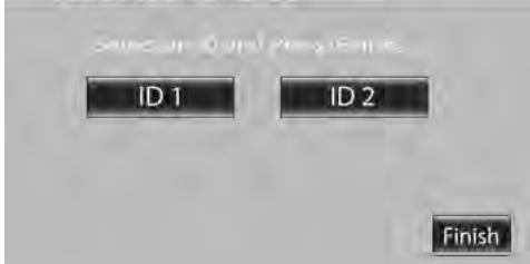
text_image
SINCE UP OUT PASE FINI ID 1 ID 2 Finishnatural_image
Exterior view of a modern parking lot with curved parking areas and a large building in the background (no signage or text visible)Groothoekbeeld
natural_image
Exterior view of a parking lot with lanes and overhead lighting (no signage or text visible)Bovenaanzicht
natural_image
Close-up of a U-shaped metal frame against a dark background (no text or symbols visible)PinP-weergave
natural_image
Exterior view of a modern building with visible architectural elements and bare trees (no signage or text)Hoekweergave
natural_image
Exterior view of a modern parking lot with curved white pavement markings (no signage or text visible)Camera-eenheid (CMOS-300)
Uitvoervideo
natural_image
Two types of cable connectors shown in line drawings, no text or symbols presentnatural_image
Technical line drawing of a rectangular housing with a side panel, no text or symbols presentnatural_image
Line drawing of a coiled cable with connectors and connectors (no text or symbols)Imballaggio impermeabile .....1
natural_image
Technical line drawing of a saw and a screw (no text or symbols)Solo CMOS-300
natural_image
Illustration of a coiled cable with a connector and a separate flat plate (no text or symbols)natural_image
Line drawing of a coiled cable with connectors (no text or symbols)text_image
12-34 O Xnatural_image
Two black-and-white photos: one showing a curved mechanical device with rotational arrow, the other showing a road with lane markings and a distant building (no text or symbols)natural_image
Interior view of a car showing dashboard, steering wheel, and cable connector (no text or symbols)natural_image
Line drawing of a car interior showing steering wheel and dashboard, with a close-up of the dashboard panel (no text or symbols)Collegamenti
natural_image
Top-down line drawing of a car showing front, side, and perspective views (no text or symbols)text_image
SAFETY PRECAUTIONS (Processing Mirror Image Setup) 1/13 Observe the following precautions - During setting check that your surroundings are safe and ensure that you engage the foot brake and parking brake. - Perform the setting in an area out of the way of other vehicles. For use on unrematted below I should be aware of the next 20 days. The security has been Reset All Switch to Normal Image Display OK1 Selezionare "OVERHEAD VIEW IMAGE ADJUSTMENT (Right-and-Left ANGLE)".
text_image
OVERHEAD VIEW IMAGE ADJUSTMENT (Right-and-Left ANGLE) 3/13 Back Reset Nexttext_image
OVERHEAD VIEW IMAGE ADJUSTMENT (Up-and-Down ANGLE) 4/13 Back Reset Nexttext_image
WIDE VIEW GUIDELINE ADJUSTMENT (Size) 5/13 Back Next Resettext_image
WIDE VIEW GUIDELINE ADJUSTMENT (Horizontal direction) Back Next Reset 6/13text_image
WIDE VIEW GUIDELINE ADJUSTMENT (Vertical direction) Back Next Resettext_image
WIDE VIEW GUIDELINE ADJUSTMENT (Red Line Position Setting) 8/13 Back Next ResetPagina successiva ▶
text_image
OVERHARD VIEW GUIDELINE ADJUSTMENT (Horizontal direction) 10/13 Back + + + + + Next Resettext_image
OVERHARD VIEW GUIDELINE ADJUSTMENT (Vertical direction) 11/13 Back + + + + Next Reset ↑↓text_image
OVERHARD VIEW GUIDELINE ADJUSTMENT (Red Line Position Setting) 12/13 Back + - + - + - Next Reset ↑↓text_image
SETTING COMPLETE The setting has been completed. ▲ Observe the following precautions - Always make sure to visually check behind and around your car. Back Reset All Finish 13/13text_image
When connecting two CMOS-300 cameras to a head unit, that supports this feature, using the supplied cable it is necessary to register separate IDs for each camera. ID 1 ID 2 Finishnatural_image
Exterior view of a modern parking lot with lanes and a distant building (no signage or text visible)natural_image
Black and white photo of a parking lot with lanes and windows, no visible text or symbolsnatural_image
Close-up of a U-shaped metal frame with horizontal lines, against a dark background (no text or symbols)natural_image
Black and white exterior view of a modern building with visible windows and bare trees, no text or symbols present.natural_image
Exterior view of a modern building with curved road markings, captured in black and white (no visible text or symbols)natural_image
Two types of cable or wire connectors, one with a small sensor and the other with a plug (no text or symbols visible)natural_image
Technical line drawing of a rectangular housing and a flat rectangular panel (no text or symbols)natural_image
Line drawing of a coiled cable with connectors and a connector (no text or symbols)Envasado resistente al agua......1
natural_image
Simple line drawing of a saw and a screw (no text or symbols)Solo CMOS-300
natural_image
Line drawing of a coiled cable with a connector and a separate flat surface (no text or symbols)natural_image
Line drawing of a coiled cable with connectors (no text or symbols)text_image
12-34 O Xnatural_image
Interior view of a car showing dashboard, steering wheel, and cable connector (no text or symbols)natural_image
Line drawing of a car interior showing a seatbelt switch and a mounted device (no text or symbols)Conexiones
Conexiones básicas
natural_image
Top-down line drawing of a car showing front, side, and side views with no text or symbolstext_image
SAFETY PRECAUTIONS (Processing Mirror Image Setup) 1/13 Observe the following precautions - During setting check that your surroundings are safe and ensure that you engage the foot brake and parking brake. - Perform the setting in an area out of the way of other vehicles. Please see on an unremarded below Reset All Switch to Normal Image Display OK1 Seleccione "OVERHEAD VIEW IMAGE ADJUSTMENT (Right-and-Left ANGLE)".
text_image
OVERHEAD VIEW IMAGE ADJUSTMENT (Right-and-Left ANGLE) 3/13 Back Reset Nexttext_image
OVERHEAD VIEW IMAGE ADJUSTMENT (Up-and-Down ANGLE) 4/13 Back Next Resettext_image
WIDE VIEW GUIDELINE ADJUSTMENT (Size) 5/13 Back Next Resettext_image
WIDE VIEW GUIDELINE ADJUSTMENT (Horizontal direction) Back Next 6/13 Resettext_image
WIDE VIEW GUIDELINE ADJUSTMENT (Vertical direction) Back Next Resettext_image
WIDE VIEW GUIDELINE ADJUSTMENT (Red Line Position Setting) 8/13 Back + + + + - - - - - - - - Next Reset ↑↓Página siguiente ▶
text_image
OVERHARD VIEW GUIDELINE ADJUSTMENT (Horizontal direction) 10/13 Back + + + + + Next Resettext_image
OVERHARD VIEW GUIDELINE ADJUSTMENT (Vertical direction) 11/13 Back + - + - + - Next Reset ↑↓text_image
OVERHARD VIEW GUIDELINE ADJUSTMENT (Red Line Position Setting) 12/13 Back + - + - + - Next Reset ↑↓text_image
SETTING COMPLETE The setting has been completed. ▲ Observe the following precautions - Always make sure to visually check behind and around your car. Back Reset All Finish 13/13text_image
When connecting two CMOS-300 cameras to a head unit, that supports this feature, using the supplied cable it is necessary to register separate IDs for each camera. ID 1 ID 2 Finishnatural_image
Exterior view of a modern parking lot with lanes and a large building in the background (no signage or text visible)Vista amplia
natural_image
Exterior view of a parking garage with lane markings and overhead lighting (no signage or text visible)Vista aérea
natural_image
Close-up of a U-shaped metal object with horizontal lines, against a dark background (no text or symbols visible)Vista PinP
natural_image
Exterior view of a modern building with bare trees and road markings (no signage)Vista de la esquina
natural_image
Exterior view of a parking lot with curved parking markings and parked cars (no signage or text visible)Especificaciones
natural_image
Two types of cable or connector packages, one with a small sensor and the other with a plug (no text or symbols visible)natural_image
Technical line drawing of a rectangular housing with a flat roof and a flat base (no text or symbols)natural_image
Line drawing of a coiled cable with connectors and connectors (no text or symbols)natural_image
Simple line drawing of a 3D rectangular prism and a screw (no text or symbols)Apenas CMOS-300
natural_image
Line drawing of a coiled cable with a connector and a separate flat surface (no text or symbols)natural_image
Line drawing of a coiled cable with connectors (no text or symbols)text_image
12:34 O Xnatural_image
Two-panel image: left shows a mechanical device with rotational arrow, right shows a facility exterior view (no text or symbols)natural_image
Interior view of a car dashboard with steering wheel, dashboard panel, and cable connector (no text or symbols)natural_image
Line drawing of a car interior showing a valve and a close-up of a mounted device (no text or symbols)Ligações básicas
natural_image
Top-down line drawing of a car showing front, side, and side views with no text or symbolstext_image
SAFETY PRECAUTIONS (Processing Mirror Image Settings) 1/13 Observe the following precautions - During setting check that your surroundings are safe and ensure that you engage the foot brake and parking brake. - Perform the setting in an area out of the way of other vehicles. Reset All Switch to Normal Image Display OKflowchart
graph TD
    A["Back"] --> B["+"]
    C["Reset"] --> D["-"]
    E["Next"] --> F["+"]
    G["Arrow Up/Down"] --> H["Arrow Down/Up"] --> I["Arrow Up/Down"] --> J["Arrow Down/Up"] --> K["Arrow Up/Down"] --> L["Arrow Down/Up"] --> M["Arrow Up/Down"] --> N["Arrow Down/Up"] --> O["Arrow Up/Down"] --> P["Arrow Down/Up"] --> Q["Arrow Up/Down"] --> R["Arrow Down/Up"] --> S["Arrow Up/Down"] --> T["Arrow Down/Up"] --> U["Arrow Up/Down"] --> V["Arrow Down/Up"] --> W["Arrow Up/Down"] --> X["Arrow Down/Up"] --> Y["Arrow Up/Down"] --> Z["Arrow Down/Up"] --> AA["Arrow Up/Down"] --> AB["Arrow Down/Up"] --> AC["Arrow Up/Down"] --> AD["Arrow Down/Up"] --> AE["Arrow Up/Down"] --> AF["Arrow Down/Up"] --> AG["Arrow Up/Down"] --> AH["Arrow Down/Up"] --> AI["Arrow Up/Down"] --> AJ["Arrow Down/Up"] --> AK["Arrow Up/Down"] --> AL["Arrow Down/Up"] --> AM["Arrow Up/Down"] --> AN["Arrow Down/Up"] --> AO["Arrow Up/Down"] --> AP["Arrow Down/Up"] --> AQ["Arrow Up/Down"] --> AR["Arrow Down/Up"] --> AS["Arrow Up/Down"] --> AT["Arrow Down/Up"] --> AU["Arrow Up/Down"] --> AV["Arrow Down/Up"] --> AW["Arrow Up/Down"] --> AX["Arrow Down/Up"] --> AY["Arrow Up/Down"] --> AZ["Arrow Down/Up"] --> BA["Arrow Up/Down"] --> BB["Arrow Down/Up"] --> BC["Arrow Up/Down"] --> BD["Arrow Down/Up"] --> BE["Arrow Up/Down"] --> BF["Arrow Down/Up"] --> BG["Arrow Up/Down"] --> BH["Arrow Down/Up"] --> BI["Arrow Up/Down"] --> BJ["Arrow Down/Up"] --> BK["Arrow Up/Down"] --> BL["Arrow Down/Up"] --> BM["Arrow Up/Down"] --> BN["Arrow Down/Up"] --> BO["Arrow Up/Down"] --> BP["Arrow Down/Up"] --> BQ["Arrow Up/Down"] --> BR["Arrow Down/Up"] --> BS["Arrow Up/Down"] --> BT["Arrow Down/Up"] --> BU["Arrow Up/Down"] --> BV["Arrow Down/Up"] --> BW["Arrow Up/Down"] --> BX["Arrow Down/Up"] --> BY["Arrow Up/Down"] --> BZ["Arrow Down/Up"] --> CA["Arrow Up/Down"] --> CB["Arrow Down/Up"] --> CC["Arrow Up/Down"] --> CD["Arrow Down/Up"] --> CE["Arrow Up/Down"] --> CF["Arrow Down/Up"] --> CG["Arrow Up/Down"] --> CH["Arrow Down/Up"] --> CI["Arrow Up/Down"] --> CJ["Arrow Down/Up"] --> CK["Arrow Up/Down"] --> CL["Arrow Down/Up"] --> CM["Arrow Up/Down"] --> CN["Arrow Down/Up"] --> CO["Arrow Up/Down"] --> CP["Arrow Down/Up"] --> CQ["Arrow Up/Down"] --> CR["Arrow Down/Up"] --> CS["Arrow Up/Down"] --> CT["Arrow Down/Up"] --> CU["Arrow Up/Down"] --> CV["Arrow Down/Up"] --> CW["Arrow Up/Down"] --> CX["Arrow Down/Up"] --> CY["Arrow Up/Down"] --> CZ["Arrow Down/Up"] --> DA["Arrow Up/Down"] --> DB["Arrow Down/Up"] --> DC["Arrow Up/Down"] --> DD["Arrow Down/Up"] --> DE["Arrow Up/Down"] --> DF["Arrow Down/Up"] --> DG["Arrow Up/Down"] --> DH["Arrow Down/Up"] --> DI["Arrow Up/Down"] --> DJ["Arrow Down/Up"] --> DK["Arrow Up/Down"] --> DL["Arrow Down/Up"] --> DV["Arrow Up/Down"] --> DW["Arrow Down/Up"] --> DX["Arrow Up/Down"] --> DXB["Arrow Down/Up"] --> DXC["Arrow Up/Down"]
1 Seleccione "OVERHEAD VIEW IMAGE ADJUSTMENT (Right-and-Left ANGLE)"
text_image
OVERHEAD VIEW IMAGE ADJUSTMENT (Right-and-Left ANGLE) 3/13 Back Reset Nexttext_image
WIDE VIEW GUIDELINE ADJUSTMENT (Size) 5/13 Back + - + + - + - Next Reset ↑↓text_image
WIDE VIEW GUIDELINE ADJUSTMENT (Horizontal direction) Back Next Reset 6/13text_image
WIDE VIEW GUIDELINE ADJUSTMENT (Vertical direction) Back Next Resettext_image
WIDE VIEW GUIDELINE ADJUSTMENT (Red Line Position Setting) 8/13 Back Next ResetPágina seguinte ▶
text_image
OVERHARD VIEW GUIDELINE ADJUSTMENT (Horizontal direction) 10/13 Back + + + + + Next Resettext_image
OVERHARD VIEW GUIDELINE ADJUSTMENT (Vertical direction) 11/13 Back + - + + + Next Reset ↑↓text_image
SETTING COMPLETE The setting has been completed. ▲ Observe the following precautions - Always make sure to visually check behind and around your car. Back Reset All Finish 13/13text_image
When connecting two CMOS-300 cameras to a head unit, that supports this feature, using the supplied cable it is necessary to register separate IDs for each camera. ID 1 ID 2 Finishnatural_image
Exterior view of a modern parking lot with empty lanes and a large building in the background (no signage or text visible)Visualização ampla
natural_image
Black and white photo of a parking lot with lanes and windows, no visible text or symbolsVisualização aérea
natural_image
Close-up of a U-shaped metal frame with horizontal lines, against a dark background (no text or symbols)Visualização PinP
natural_image
Black-and-white exterior view of a modern building with visible windows and bare trees, no text or symbols present.Vista do canto
natural_image
Exterior view of a modern parking lot with curved white pavement markings (no signage or text visible)Especificações
Declaration of Conformity with regard to the EMC Directive 2004/108/EC
Manufacturer:
Kenwood Corporation
2967-3 Ishikawa-machi, Hachioji-shi, Tokyo, 192-8525 Japan
EU Representative's:
Kenwood Electronics Europe BV
Amsterdamseweg 37, 1422 AC UITHOORN, The Netherlands
Français
NOTICE: This Class B digital apparatus complies with Canadian ICES-003.
THIS DEVICE COMPLIES WITH PART 15 OF THE FCC RULES. OPERATION IS SUBJECT TO THE FOLLOWING TWO CONDITIONS:
(1) THIS DEVICE MAY NOT CAUSE HARMFUL INTERFERENCE, AND (2) THIS DEVICE MUST ACCEPT ANY INTERFERENCE RECEIVED, INCLUDING INTERFERENCE THAT MAY CAUSE UNDESIRED OPERATION.
FCC WARNING
This equipment may generate or use radio frequency energy. Changes or modifications to this equipment may cause harmful interference unless the modifications are expressly approved in the instruction manual. The user could lose the authority to operate this equipment if an unauthorized change or modification is made.
FCC NOTE
This equipment has been tested and found to comply with the limits for a Class B digital device, pursuant to Part 15 of the FCC Rules. These limits are designed to provide reasonable protection against harmful interference in a residential installation. This equipment may cause harmful interference to radio communications, if it is not installed and used in accordance with the instructions. However, there is no guarantee that interference will not occur in a particular installation. If this equipment does cause harmful interference to radio or television reception, which can be determined by turning the equipment off and on, the user is encouraged to try to correct the interference by one or more of the following measures:
- Reorient or relocate the receiving antenna.
- Increase the separation between the equipment and receiver.
- Connect the equipment into an outlet on a circuit different from that to which the receiver is connected.
- Consult the dealer or an experienced radio/TV technician for help.