CPS 2 - Exercise bike Christopeit - Free user manual and instructions
Find the device manual for free CPS 2 Christopeit in PDF.

| Features | Details |
|---|---|
| Product type | Exercise bike |
| Dimensions | Length: 110 cm, Width: 50 cm, Height: 130 cm |
| Maximum user weight | 110 kg |
| Resistance system | Magnetic resistance |
| Training programs | 8 resistance levels |
| Screen | LCD display with information on distance, time, calories, and speed |
| Comfort | Height-adjustable seat |
| Transport | Built-in transport wheels |
| Maintenance | Regularly check screws and bolts, clean after use |
| Safety | Stable balance, non-slip feet |
| Warranty | 2 years |
Frequently Asked Questions - CPS 2 Christopeit
User questions about CPS 2 Christopeit
0 question about this device. Answer the ones you know or ask your own.
Ask a new question about this device
Download the instructions for your Exercise bike in PDF format for free! Find your manual CPS 2 - Christopeit and take your electronic device back in hand. On this page are published all the documents necessary for the use of your device. CPS 2 by Christopeit.
USER MANUAL CPS 2 Christopeit
Assembly and exercise instructions for Order No. 9912
F
- Summary of Parts Page 3
- Important Recommendations and Safety Information Page 10
- Parts List Page 11-12
- Assembly Instructions With Exploded Diagrams Page 13 - 15
- Computer instructions Page 15
- Training Instructions Page 16
Dear customer,
We congratulate you on your purchase of this home training sports unit and hope that we will have a great deal of pleasure with it. Please take heed of the enclosed notes and instructions and follow them closely concerning assembly and use.
Please do not hesitate to contact us at any time if you should have any questions.
Important Recommendations and Safety Instructions
Our products are all TUV-GS tested and therefore represent the highest current safety standards. However, this fact does not make it unnecessary to observe the following principles strictly.
- Assembly the machine exactly as described in the installation instructions and use only the enclosed, specific parts of the machine contained in the parts list. Before assembling, verify the completeness of the delivery against the delivery notice and the completeness of the carton against the parts list in the installation and operating instructions.
- Check the firm seating off all screws, nuts and other connections before using the machine for the first time and at regular intervals to ensure that the trainer is in a safe condition.
- Set up the machine in a dry, level place and protect it from moisture and water. Uneven parts of the floor must be compensated by suitable measures and by the provided adjustable parts of the machine if such are installed. Ensure that no contact occurs with moisture or water.
- Place a suitable base (e.g. rubber mat, wooden board etc.) beneath the machine if the area of the machine must be specially protected against indentations, dirt etc.
-
Before beginning training, remove all objects within a radius of 2 metres from the machine.
-
Do not use aggressive cleaning agents to clean the machine and employ only the supplied tools or suitable tools of your own to assemble the machine and for any necessary repairs. Remove drops of sweat from the machine immediately after finishing training.
-
Your health can be impaired by incorrect or excessive training. Consult a doctor before beginning a planned training programme. He can define the maximum exertion (pulse, Watts, duration of training etc.) to which you may expose yourself and can give you precise information on the correct posture during training, the targets of your training and your diet. Never train after eating large meals. Observe that this machine is not suitable for therapeutic purposes.
- Only train on the machine when it is in correct working order. Use original spare parts only for any necessary repairs.
-
When setting the adjustable parts, observe the correct position and the marked, maximum setting positions and ensure that the newly adjusted position is correctly secured.
-
Unless otherwise described in the instructions, the machine must only be used for training by one person at a time.
- Wear training clothes and shoes which are suitable for fitness training with the machine. Your clothes must be such that they cannot catch during training due to their shape (e.g. length). Your training shoes should be appropriate for the trainer, must support your feet firmly and must have nonslip soles.
-
If you notice a feeling of dizziness, sickness, chest pain or other abnormal symptoms, stop training and consult a doctor.
-
Never forget that sports machines are not toys. They must therefore only be used according to their purpose and by suitably informed and instructed persons.
- People such as children, invalids and handicapped persons should only use the machine in the presence of another person who can give aid and advice. Take suitable measures to ensure that children never use the machine without supervision.
-
Ensure that the person conducting training and other people never move or hold any parts of their body into the vicinity of moving parts.
-
At the end of its life span this product is not allowed to dispose over the normal household waste, but it must be given to an assembly point for the recycling of electric and electronic components. You may find the symbol on the product, on the instructions or on the packing.
The materials are reusable in accordance with their marking. With the reuse, the material utilization or the protection of our environment. Please ask the local administration for the responsible disposal place. - This machine is a speed-dependant machine, i.e. the power increases with increasing speed, and the reverse.
The machine is equipped with 8-speed resistance which allows the braking resistance and thereby the training exertion to be reduced or increased. Turning the adjusting knob for the resistance setting towards stage 1 reduces the braking resistance and thereby the training exertion. Turning the adjusting knob for the resistance setting towards stage 8 increases the braking resistance and thereby the training exertion. - This machine has been tested and certified in compliance with EN 957-1 and -5 "H. C". The maximum permissible load (=body weight) is specified as 100kg .
Parts List - Spare Parts List
CPS 2 Order No. 9912
Technical data:
Issue: 01.03.2006
Magnetic brake system
Approx. 6kg centrifugal mass
8-stage gear shift
Hand pulse measurement
height adjustable saddle
Ergonomically optimised handlebar shape
Comfort saddle
Transport rollers at front foot
Easy to use computer with digital display of:
Time, distance, speed, approx. calorie consumption and pulse rate.
Load max. 100 kg (Body weight)
Space requirement approx. L 97 x B 55 x H 137cm
Please check after opening the packing that all the parts shown in the following parts lists are there. Once you are sure that this is the case, you can start assembly.
Please contact us if any components are defective or missing, or if you need any spare parts or replacements in future:
Assembly Instructions
Before beginning assembly, be sure to observe our recommendations and safety instructions.
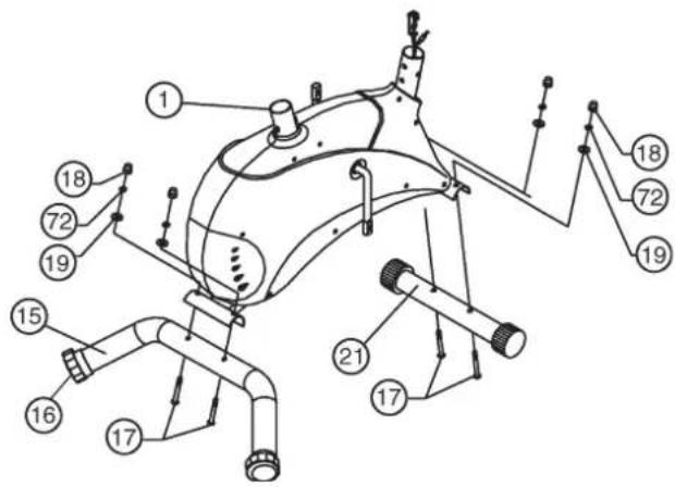
Step 1: Install of the front footbar (21) and the rear footbar (15) on the main frame (1) with the carriage bolts M8x60 (17), the washers 8//20 /19), the spring washers for M8 (72) and the cap nuts M8 (18).
- Place screws (17) and two each washers (19), spring washers (72) and nuts (18) accessibly beside the front and rear parts of the main frame (1).
- Insert the footbars (21) + (15) in the holder of the main frame (1) and adjust so that the hole patterns of the holders and the footbars (21) + (15) are aligned.
- Push one screw (17) through each hole.
- Fit the screw ends of (17) with one washer (19) and one spring washer (72) each and fasten with a nut (18).
(Note: If the machine is placed for training on an uneven floor, this can be compensated at any tome by turning the eccentric caps (16).
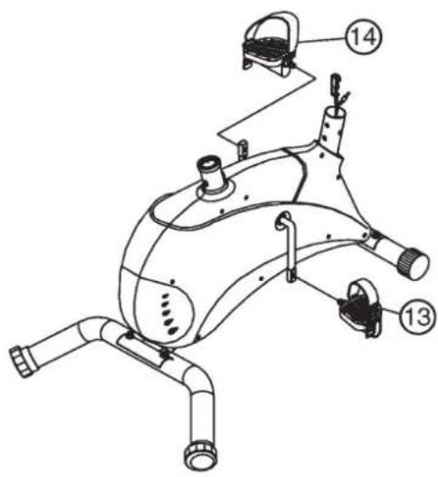
Step 2: Installation of the right pedals (13) and the left pedals (14) on the pedal crank.
- The pedals are marked "R" for right and "L" for left.
- Screw the right pedal (13) into the threaded hole on the right hand side of the pedal crank (9) and tighten firmly. (Note: Right and left are specified as viewed seated on the machine during training. It must also be observed that the threaded part of the right pedal must be screwed clockwise into the threaded hole of the pedal crank.)
- Screw the left pedal (14) into the threaded hole on the left hand side of the pedal crank (9) and tighten firmly. (Note: The threaded part of the left pedal must be screwed anticlockwise into the threaded hole of the pedal crank.)
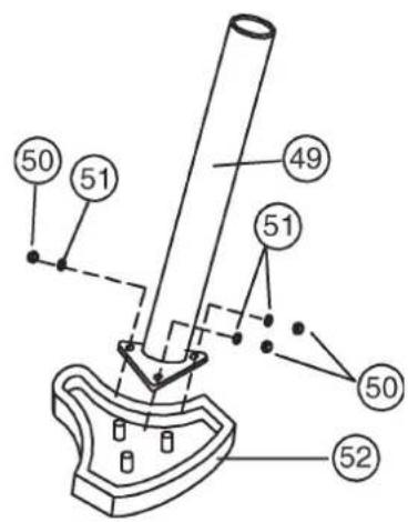
Step 3: Installation of the saddle (52) on the saddle support (49) with the washers 8 / 20mm (51) and the self-locking nuts M8 (50).
- Place the saddle (52) with the seat surface downwards.
- Place the retaining plate of the saddle support (49) on the upwards pointing bottom of the saddle (52). The threaded pieces on the bottom of the saddle must project through the corresponding holes in the retaining plate of the saddle support (49).
- Place washers (51) on the threaded pieces, screw on nuts (51) and tighten firmly.
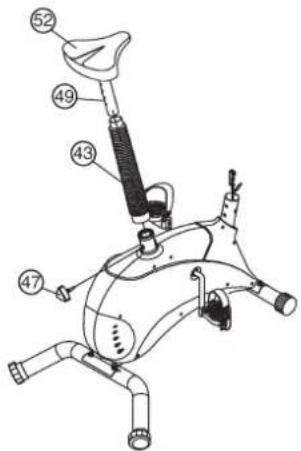
Step 4: Installation of the saddle support (49) on the main frame (1) with the saddle support screw (47).
- Push the saddle support wrapping (43) onto the saddle support (49). Insert the saddle support (49) into the provided holder of the main frame (1) and secure at the desired position by screwing in the saddle support screw (47). (Note: To screw in the saddle support screw (47), the threaded hole in the main frame (1) and one of the holes in the saddle support (49) must be aligned. Furthermore, ensure that the saddle support (49) is not pulled out of the main frame beyond the marked maximum adjustment position. The setting of the saddle support can be adjusted as desired later.)
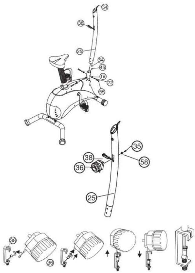
Step 5: Connecting the computer cable harness incl. sensor (45) to the computer cable harness (54), connection of the cable of the resistance adjuster (38) with the resistance adjusting unit (36) and installation of the handlebar support (25) on the main frame (1) with the round-headed Allen screws M8x15 (55), washers 8//20 (19) and spring washers for M8 (72).
- Place the lower end of the handlebar support (25) against the main frame (1). Plug the ends of the two computer cable harnesses (45) and (54) projecting from (1) and (25) together.
- When the cable connections have been made, push the cable (38) from the bottom through the handlebar support (25) and pull out of the opening at the upper end of the tube. Then push the handlebar support (25) onto the main frame (1). (Note: When joining the tubes, ensure that the harness and cable connections are not trapped.
- Put one spring washer and one washer on each screw. Push the screws through the holes in the support, screw into the threaded holes of the main frame (1) and tighten firmly.
- Join the two ends of the cables (36) and (38) as indicated in the drawing below (A+B).
(Note: Before this step of the installation, it is advisable to adjust the resistance setting to the highest stage, at which the cable extends furthest from the sheath. If the factory adjusted pedal resistance range of the machine should later be found to be too great or too small, this can be simply adjusted as the cables. For this, loosen nut of cable (38), turn the threaded piece correspondingly and secure the new position with nut. In this respect: The further is screwed into the U-piece, the greater the resistance, and the converse.) When the connection has been made, insert the resistance adjusting unit (36) into the opening of the handlebar support (25) and secure with screw (35).
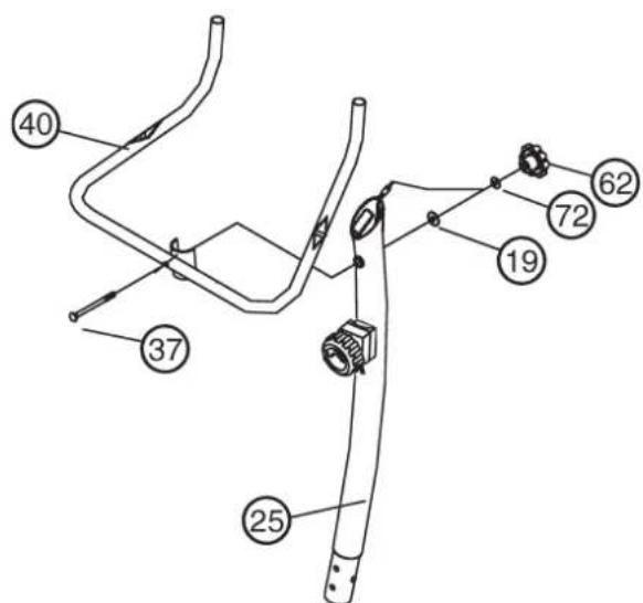
Step 6: Installation of the handlebar (40) on the handlebar support (25) with the carriage bolt M8x90 (57), the spring washer for M8 (72), the washer 8//20 (19) and the handgrip nut (62).
- Place the handlebar (40) against the handlebar support (25) and adjust so that the hole patterns in the handlebar and the handlebar support are aligned. Put the screw (57) into the hole, push the washer (19), the spring washer (72) on screw end and tighten firmly with the handgrip nut (62).
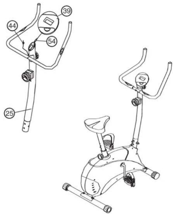
Step 7: Installation of the computer (39) on the computer bracket of the handlebar support (25).
- Push the plug of the computer cable harness (54) into the appropriate socket of the computer (39). Push the plugs of the pulse measuring unit (44) into the appropriate sockets of the computer and push the computer onto the computer bracket.
(Note: when pushing on the computer, ensure that the cable harnesses are not trapped. Insert the necessary batteries (2xMignon 1.5V AA) in the battery compartment located on the rear of the computer.)
Step 8:
Checks
- Check the correct installation and function of all screwed and plug connections. Installation is thereby complete.
- When everything is in order, familiarise yourself with the machine at a low resistance setting and make your individual adjustments.
Note:
Please keep the tool set and the instructions in a safe place as these may be required for repairs or spare parts orders becoming necessary later.
Computer instructions for 9912
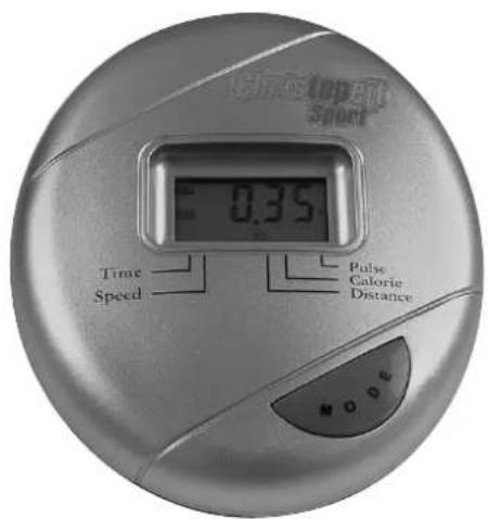
The supplied computer allows the most convenient training. Every value relevant to training is displayed in the window.
From the beginning of the training session, the required time, the current speed, the approximate calorie consumption, the travelled distance ad the current pulse rate are displayed. All values are counted from zero upwards. The computer is switched on by briefly pressing the F key or simply by beginning training.
To start the computer, simply begin training. The computer begins to register and display all values.
To stop the computer, just stop training. The computer stops all measurements and retains the last attained values. The last attained values in the functions TIME, CALORIES and KM are stored and training can continue with these values when training is resumed.
The computer switches of automatically approx. 4 minutes after training is stopped. All previously attained values are deleted.
Displays:
With the "F" key, the individual functions can be selected and the associated data displayed in the window. The selected function is indicated by an icon in the window beside the printed name of the function.
1. "PULSE" display:
The current pulse rate is displayed in beats per minute. Particular values cannot be specified.
The values last attained by this function are not stored.
(Limit of both displays: 240 pulse beats per minute.)
(Note: For pulse measurement, the two contact surfaces of the pulse measuring handle unit (19) must be gripped simultaneously. The contact surfaces should be located centrally in the palms of the hands.
2. "TIME" display:
The currently required time is displayed in minutes and seconds. A particular value cannot be specified.
The values last attained by this function are not stored.
(Limit of the display: 99.59 minutes.)
3. "KM/H" display:
The current speed is displayed in kilometres per hour. A particular value cannot be specified.
The values last attained by this function are not stored.
(Limit of the display: 99.9km / h
4. "CALORY" display:
The current status of the consumed calories is displayed. A particular value cannot be specified.
The values last attained by this function are not stored.
(Limit of the display: 999,9 calories.)
5. "KM" display:
The current status of the travelled distance is displayed. A particular value cannot be specified.
The values last attained by this function are not stored.
(Limit of the display: 999,9 km.)
6. "SCAN" function:
If this function is selected, the current values of all functions are displayed successively in a constant sequence approx. every 5 seconds.
Key functions:
1. "F" key
By pressing this key once briefly, it is possible to change from one function to another. The associated values are then displayed in the window.
If the key is held longer (approx. 3 seconds), all last attained values are deleted with the exception of the values in the "KM TOTAL" display.
You must consider the following factors in determining the amount of training effort required in order to attain tangible physical and health benefits:
1. Intensity:
The level of physical exertion in training must exceed the level of normal exertion without reaching the point of breathlessness and / or exhaustion. A suitable guideline for effective training can be taken from the pulse rate. During training this should rise to the region of between 70% to 85% of the maximum pulse rate (see the table and formular for determination and calculation of this).
During the first weeks, the pulse rate should remain at the lower end of this region, at around 70% of the maximum pulse rate. In the course of the following weeks and months, the pulse rate should be slowly raised to the upper limit of 85% of the maximum pulse rate. The better the physical condition of the person doing the exercise, the more the level of training should be increased to remain in the region of between 70% to 85% of the maximum pulse rate. This should be done by lengthening the time for the training and/or encreasing the level of difficulty.
If the pulse rate is not shown on the computer display or if for safety reasons you wish to check your pulse rate, which could have been displayed wrongly due to error in use, etc., you can do the following:
a. Pulse rate measurement in the conventional way (feeling the pulse at the wrist, for example, and counting the number of beats in one minute).
b. Pulse rate measurement with a suitable specialised device (available from dealers specialising in health-related equipment).
2.Frequency
Most experts recommend a combination of health-conscious nutrition, which must be determined on the basis of your training goal, and physical training three times a week. A normal adult must train twice a week to maintain his current level of condition. At least three training sessions a week are required to improve one's condition and reduce one's weight. Of course the ideal frequency of training is five sessions a week.
3. Planning the training
Each training session should consist of three phases: the warm-up phase, the training phase, and the cool-down phase. The body temperature and oxygen intake should be raised slowly in the warm-up phase. This can be done with gymnastic exercises lasting five to ten minutes.
Then the actual training (training phase) should begin. The training exertion should be relatively low for the first few minutes and then raised over a period of 15 to 30 minutes such that the pulse rate reaches the region of between 70% to 85% of the maximum pulse rate.
In order to support the circulation after the training phase and to prevent aching or strained muscles later, it is necessary to follow the training phase with a cool-down phase. This should be consistent of stretching exercises and / or light gymnastic exercises for a period of five to ten minutes.
4. Motivation
The key to a successful program is regular training. You should set a fixed time and place for each day of training and prepare yourself mentally for the training. Only train when you are in the mood for it and always have your goal in view. With continuous training you will be able to see how you are progressing day by day and are approaching your personal training goal bit by bit.
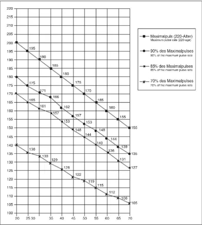
Calculation formula: Maximum pulse rate = 220 - age
(220 minus your age)
90% of the maximum pulse rate = (220 - age) x 0.9
85% of the maximum pulse rate = (220 - age) x 0.85
70% of the maximum pulse rate = (220 - age) x 0.7

Chere cliente, cher client,
3. Planning van de training
Bce MaTePnAnbl Moryt 6bItb CHOBa NcNoIb3ObaHbI corlaCHO MapKnupOBKe. PtnoNtROPm IcNoIb3ObaHnn, BTOpNCHIpepea6OTKe nnDpyrnx fOpmax BToPnHoro NcNoIb3ObaHnCTapBx pnp60pBbBHOCTe CBOB BKnad B3auny OKpykaoue cpebl.
IoxanyiCTa,y3HaHTe B KOMMyHbHom ynpabHeHH aDpe 6JIIN3Jexaueo c6OpHOrO nyHKTa yTIN3aUN.
17.DaHHbI npB6p ABnEeTc3aBnCmBIM OT cKOpOCTn, T.e. C yBeNueHHeM YnCna OboOpOTOB MoOHocTb yBeNnuBaETcN Hao6opot.
Pnp60p Cnab6xen fckcnpyemB 8-MN NOJoxhenx perynipOBkoconpoTNBENH, KOtopa IIO3BOIeT CHN3NTb JIO6 NOBicNTb TOPMO3HOc conpoTNBENHNEu TEM CAMbIM, TpeHNPoBOUHy Harpy3Ky. Ppi 3tOM BpaueHne pyKn perynpoBKN CONPOTNBENH N HappaJIeHN CTynEHN1 BeDet K CHNXEHHO TopMO3HORO CONPOTNBENH N, TEM CAMbIM, TpeHNPoBOUHOHRarpy3Kn. BpaueHne pyKn perynpoBKN CONPOTNBENH N HappaJIeHN CTynEHN 8 BeDet K NOBIIeHNTO TropMO3HORO CONPOTNBENH N, TEM CAMbIM, TpeHNPoBOUHOHRarpy3Kn.
- Tpehakep npoewen ncbitahnH u ceptnpkaunco corlacho HOpme EN 957-1 n -5, H, C: DOnycTmam mKcImaJIbHaH Harpy3ka (=Bec TeJa) yctahOBHeHa B 100 kr.
CneuФkaua - cncok 3aapanbix<|im_start|>
CPS 2 No 3aka3a 9912
Texnueckx xapakTepnctnK: no coCToHHIO Ha: 01.03.2006
MarHHar CnCTema HarpyKeHn
HHePOnHHaMaCCa 6 K
8 ypOBHeN HArpy3Kn
N3mepenne npbca daTnKamn Ha pykoTkax
PerynpyemBbicoTa ceNa
OnTmAbhaopma pyra
YdoHoe ceNo
TpaHcnpTnpOBOHbIe pONIKN
KomnbpoTe p c nppOBo nHnKaueNe CneDyUox npaMeTpoB:
BpEMR.
DuctaHua,CKOpocTb,pn6n.pacxOdKanopn,nybc
MaKcMaJIbHbI BEc noJIb3OBaTeJr: 100 Kr
f6apuTHbpepa3Mepbipn6n.97x55xB137cm
ChnBynakobky, npOBepbTe no cnNCKy, BCE JI DeTANI Ha MeCTe. EcNI Bce B nopRdKe, To MoXHO NaHnHaTb C6OpKy. EcNI KaKo-NH6yDb arperat He B nopRdKe nIN OTCYCTByET, 06paauaITecb K Ham:
MaKc. yactota nylbca = 220 - Bo3pact
(220-Bau Bo3pact)
90% OT MaKc. yAcToTbI nyNbca= (220 - Bo3pact) x 0.9
85% OT MaKc. YacToTbI nyJbCa= (220 - Bo3pact) x 0.85
70% OT MaKc. YactOtbl nyIbca= (220 - Bo3pact) x 0.7