
Basic Ergotrainer T1670 - Exercise bike Tacx - Free user manual and instructions
Find the device manual for free Basic Ergotrainer T1670 Tacx in PDF.
| Brand | Tacx |
| Model | Basic Ergotrainer T1670 |
| Product type | Roller home trainer |
| Power supply | Mains 220-230 V / 50 Hz |
| Display | Speed (km/h or Mi/h), distance (TRP, ODO), timer, power (W), cadence (rpm), 24h clock |
| Adjustable resistance | Slope from -4 to +9 (14 levels) |
| Programmable power | 0-990 W in steps of 10 W |
| Adjustable body weight | 40-120 kg |
| Cadence sensor | Magnetic, sensor-magnet distance: approx. 3 mm |
| Bike compatibility | Wheels from 630 to 690 mm (with adaptations up to 720 mm) |
| Recommended tire pressure | At least 6 atm (4 atm for mountain bikes) |
| Dimensions (approx.) | Folding frame, dimensions not specified |
| Weight (approx.) | Not specified |
| Warranty | 1 year against manufacturing defects |
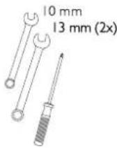
| Included accessories | Basic computer, resistance roller, cables, cadence sensor, magnet, feet and end caps, mounting tools |
| Maintenance | Dry the screen after use, check tightness of screws and nuts, check tire pressure, allow to cool after intensive use |
| Usage precautions | Do not use in humid environment, avoid sudden braking, use a slick tire to reduce noise |
Frequently Asked Questions - Basic Ergotrainer T1670 Tacx
User questions about Basic Ergotrainer T1670 Tacx
0 question about this device. Answer the ones you know or ask your own.
Ask a new question about this device
Download the instructions for your Exercise bike in PDF format for free! Find your manual Basic Ergotrainer T1670 - Tacx and take your electronic device back in hand. On this page are published all the documents necessary for the use of your device. Basic Ergotrainer T1670 by Tacx.
USER MANUAL Basic Ergotrainer T1670 Tacx
natural_image
Mechanical component diagram showing a pulley and lever mechanism (no text or symbols)6

7

8
Advies
2 EENMALIG INSTELLEN COMPUTER
7
8

9
3 GEBRUIK COMPUTER
10

11
12

13
flowchart
graph LR
    A["KM/h"] --> B["CAD"]
    B --> C["+"]
    B --> D["-"]
    C --> E["Square"]
    D --> F["Square"]
    E --> G["Square"]
    F --> H["Square"]
    G --> I["Square"]
    H --> J["Square"]
    I --> K["Square"]
    J --> L["Square"]
    K --> M["Square"]
    L --> N["Square"]
    M --> O["Square"]
    N --> P["Square"]
    O --> Q["Square"]
    P --> R["Square"]
    Q --> S["Square"]
    R --> T["Square"]
    S --> U["Square"]
    T --> V["Square"]
    U --> W["Square"]
    V --> X["Square"]
    W --> Y["Square"]
    X --> Z["Square"]
    Y --> AA["Square"]
    Z --> AB["Square"]
WATT (vermogen)
19
20
21
natural_image
Mechanical component diagram showing a lever mechanism with a labeled force H (no text or symbols beyond label)6

7
8
Hinweis
2 EINMALIGES EINSTELLEN DES COMPUTERS
7

8
9
10
11
12

13
21
24
Regenerationstraining
Make sure the following parts have been included in the packing
- Basic computer
- Frame CycleForce Basic
- Mag unit
- Cable set
- Instruction manual
- End caps and feet

2x
2x

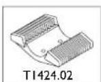
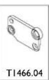
- T1466 Fitting kit adapter set

|×
lx
1x
|x

4x

4x

4x
INDEX
I Assembling Basic
Assembling the Basic trainer 41
Connecting the Basic computer 43
2 Single computer adjustment
Adjusting speed settings 44
Setting body weight 44
Setting 24-hour clock 44
3 Using the computer
MODE functions with Km/h (or Mi/h) 45
MODE key reset functions 46
+ and - key functions 46
MODE functions with WATT 47
MODE functions with CAD 47
Slope (SET-function) 48
Programmed power (SET-function) 48
Power (Watt) equals Effort times Speed 49
4 Training recommendations
Super compensation 50
Examples of training programmes 50
5 Error messages 52
6 Technical specifications &
EU Declaration of Conformity 54
7 Warranty
Procedure 55
Instructions for return shipments 55
Service form 56
Symbols Used
! Indicates an important subject. Pay attention!
Indicates an important tip. Useful information.
I ASSEMBLING BASIC
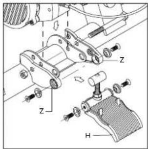
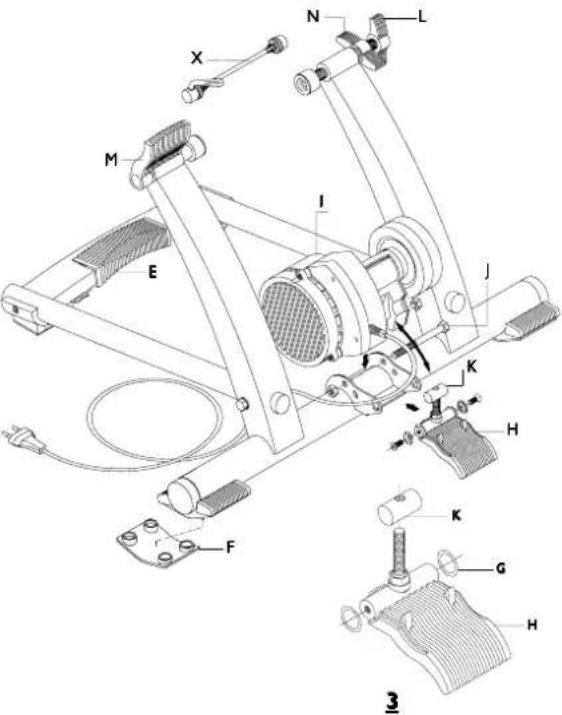
The ergotrainer Basic consists of the collapsible frame on which you mount your bike (the CycleForce trainer is standard suitable for racing and hybrid bikes and mountain bikes with a wheel diameter of 630 - 690 mm) and the Basic computer.
Assembling the Trainer
The following steps show how to assemble and adjust the trainer.
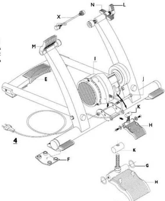
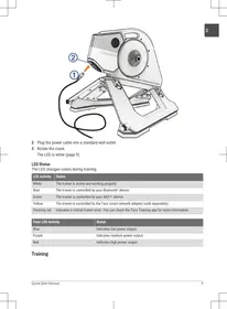
I Press nut A into cap B and slide the cap into the frame tube (fig. 1).
2 Assemble base C to the frame using bolt D. Tighten bolt D but make sure the base is still adjustable.
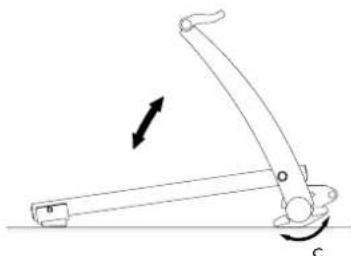
3 Unfold the trainer and place it on a level surface. By fully squeezing grip E, the trainer can be folded out or collapsed (fig. 1).
4 Turn base C to the correct position (fig. 2). Tighten bolt D firmly and attach anti-slip rubber F (fig. 4).
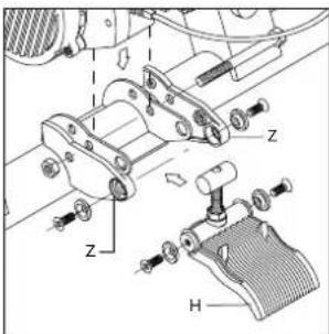
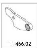
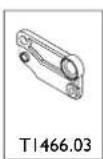
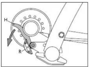
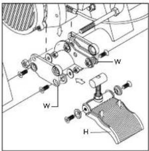
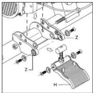
5 Assemble 2 rubber rings G and part K to handle H (fig. 3). Than assemble the complete handle to the frame, shove unit I into part K of the handle and turn bolt J until the mag unit is firmly tightened but it should still be able to move (fig. 4).
6 Replace the quick-release skewer on the rear wheel with the skewer X supplied by Tacx. This assures ideal clamp fitting and stability. Place the bike in the trainer and adjust the wing bolt L of the trainer, so that the speed tension clamp M will close without forcing. Forcing could cause damage!
7 Fix wing bolt L by tightening wing nut N.
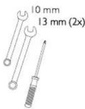

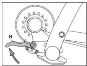
8 With handle H the roll of the mag unit can be moved to and from the tire of the bike (fig. 5 and 6). When handle H has been folded, knob R can be used to regulate the pressure of the roll against the tire. Make sure the roll is firmly placed against the tire so that slipping of the tire is not possible.
5
natural_image
Mechanical component diagram showing a wheel and lever mechanism (no text or symbols)6

Alteration in mounting of bicycle with different wheel diameter
Before assembling the complete handle to the frame, see nr. 5 of the instructions, you need to place the heightening or extension pieces.
Wheel diameter 610 - 640 mm: assemble heightening piece W with 4 bolts, nuts and rings (fig.7). Wheel diameter 690 - 720 mm: assemble extension piece Z (fig. 8).
7

8
Tip
Before using the CycleForce, after unfolding the trainer, check to see that grip E has fully returned to its original position. This will prevent damage to the frame.
- Make sure that the unit does not fall on the flywheel during assembly. This could create an imbalance in the axis, causing vibrations.
- Make sure that the tyre is well inflated (at least six atmosphere).
- ATB tyres should preferably have completely or partially smooth profiles. Rough profiles can cause noise and tyre slippage.
- Never brake abruptly while using the CycleForce. When the brakes are applied to the rear wheel, the flywheel keeps on turning. This results in unnecessary wear and tear to the rear tyre.
- Regularly check to see whether the bolts and nuts of the CycleForce are tight.
- Tests show that the unit will not overheat during high performance. Lengthy, intensive use could cause the magnetic unit's housing to heat up substantially. After use, allow the unit cool off before touching.
Connecting the Basic Computer
After placing the bike in the trainer, you can connect the computer as follows:
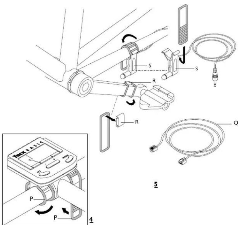
I Assemble the computer using the two rubber clamps P on the handlebars (fig. 4).
2 Connect the computer to the unit with the cable Q. Make sure that the cable is out of the way so you won't touch it with your shoes or pedals while cycling.
3 Place the small magnet in front of the cadence R on the inside of the left crankshaft (fig. 5).
4 Assemble the magnetic sensor in front of the cadence measure S on the bottom of the left-hand rear chain-stay. Make sure the sensor is level with the magnet, with a distance of approximately 3 mm between the magnet and the sensor. Insert the sensor's cable in the unit. Make sure here that the cable runs freely from the sensor and does not touch the wheel.
5 Place the plug in the power point. Check reception of the backwards. The word CAD will appear on the display. The Basic is now ready for use.
! Perspiration and humidity could damage the printer plate in the computer. Do not use the Basic in humid spaces and if necessary dry the display after use. This will prevent unnecessary damage. Incorrect use and/or improper maintenance will invalidate the warranty.
2 SINGLE COMPUTER ADJUSTMENT
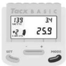
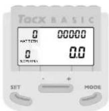
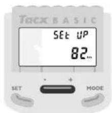
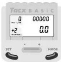
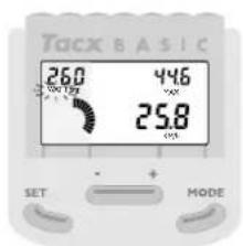
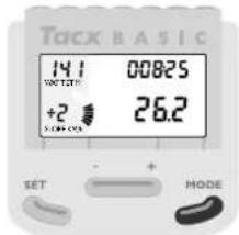
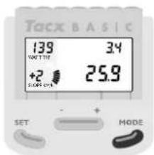
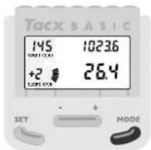
After placing the plug in the power point, the display will light up briefly for checking. The normal program status will then appear (fig. 6).
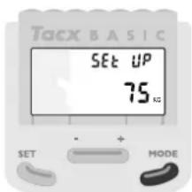
You could start right away, were it not for the fact that you will have to set your body weight the first time you use the unit. The computer has standard settings of km/h with a weight of 75 kg. When the correct speed and weight have been set, you can continue immediately in your normal program.
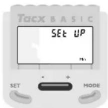
Adjusting speed settings
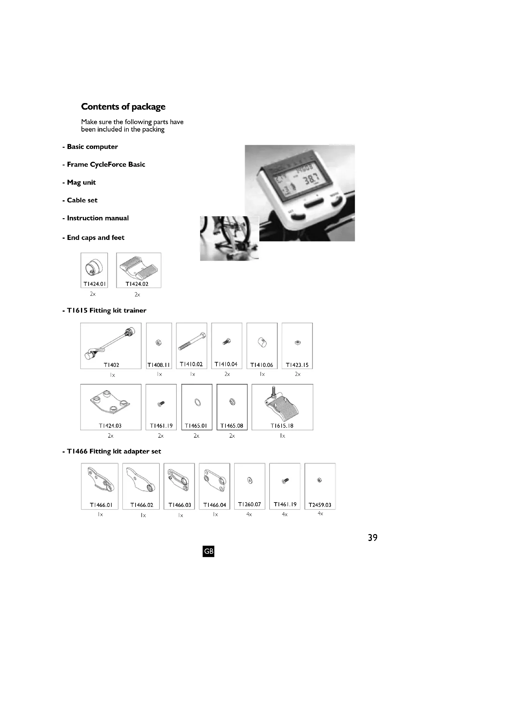
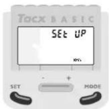
If there are adjustments necessary for speed or weight, depress the SET and MODE keys simultaneously for six seconds. The display will then show SET UP (fig. 7). By pressing the + or - symbols, you switch back and forth from km/h (kilometres per hour) to mi/h (miles per hour) (fig. 8). Select the desired speed by pressing MODE.
Setting body weight
You will now have a weight setting of 75 kg (fig. 9). By pressing the + or - key, you can change the weight in increments of 1 kilogramme (fig. 10). To enable the computer to calculate the power correctly during cycling it is essential that you set the proper weight. The power calculation is linked to your weight. Weights can be set between 40 kg and 120 kg.
Set your weight by pressing MODE. The next time you turn on the computer, it will always show the most recent weight setting. You can change the weight during a new SET UP, for example, if someone else uses the Basic to train.
Setting 24-hour clock
After having set your weight, you may set the clock on the twenty-four-hour system. If you do not wish to do so, press the MODE key twice and the normal program will appear. You will not encounter the clock during cycling.
If you wish to use the twenty-four-hour system, you must first set the hours by using the +/- keys. Then press the MODE key and set the minutes with the +/- keys. Press MODE once more and the clock will be set. The normal program will appear. You will encounter the clock as you page through the other functions. When the computer is turned off, the clock is also turned off.
If you wish to use the clock the next time you train, you should follow the new SET UP procedure given above.
6
7

8

9
3 USING THE COMPUTER
Once the computer settings are ready, you can start cycling. You can do any of the following activities while cycling on the Basic or standing still.
The Basic records three types of data. The first type concerns cycling speed. This is dealt with below. Then we will discuss the other types (power and cadence).
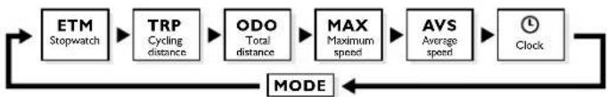
MODE functions with Km/h (or Mi/h)
The general bike functions are located under the MODE key. By successively pressing the MODE key, you will see ETM, TRP, ODO, MAX, AVS (see block diagram). If you preset the twenty-four-hour clock system, it will also appear in this group.
flowchart
graph LR
    A["ETM\nStopwatch"] --> B["TRP\nCycling distance"]
    B --> C["ODO\nTotal distance"]
    C --> D["MAX\nMaximum speed"]
    D --> E["AVS\nAverage speed"]
    E --> F["Clock"]
    F --> G["MODE"]
    G --> A
ETM (Stop Watch)
The first setting is ETM, the stop watch, at the upper right of the display (fig. 11). ETM is the cycling time before the computer is reset or turned off. The stop watch only records actual cycling time. This means you can take breaks without affecting the actual cycling time. When you turn off or reset the computer while cycling, the stop watch will start again at nil.
TRP (Cycling Distance)
By pressing MODE once more, TRP will appear in the upper right-hand corner. This is the cycling distance (fig. 12). The cycling distance is calculated as long as the computer has not been reset or turned off.
ODO (Total Distance)
The following press of the MODE key reveals ODO at the upper right-hand part of the display: the total distance travelled (fig. 13). The ODO adds up all cycling distances up to a maximum of 99,999 kilometres (or miles) and then starts again at nil.
10

11

12

13
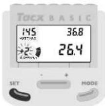
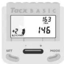
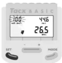
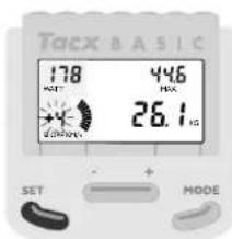
MAX (Maximum Speed)
Using the MODE key, MAX is the next abbreviation to appear in the upper right-hand corner of the display: maximum speed (fig. 14). This is the maximum speed for the period until the computer is reset or turned off.
AVS (Average Speed)
Pressing the MODE key one more time will place AVS in the upper right-hand corner: average speed. The average speed is calculated until the computer is reset or turned off.
CLOCK
If you opted to use the clock, then press MODE once again after AVS and the clock will appear on the display.
MODE Key Reset Functions
If, during a training session, you wish to reset the data recorded under ETM, TRP, MAX and AVS denominators (set again at "0"), stop cycling, wait until you have reached 0 speed and then press the SET and MODE keys simultaneously for one second (fig. 15). You cannot reset the ODO. When the odometer reaches 99,999 it will reset automatically to nil kilometres or miles.
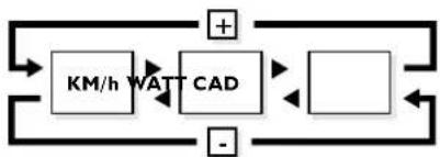
+ and - Key Functions
As mentioned previously, the Basic records three types of data:
I data relating to speed (Km/h or Mi/h).
2 data relating to the power you supply (WATT).
3 data relating to your pedalling frequency (CAD).
With the + and - key you can switch the display from speed to power, from power to cadence and back again (see block diagram).
flowchart
graph LR
    A["+"] --> B["KM/h"]
    B --> C["WAT"]
    C --> D["CAD"]
    D --> E["-"]
    E --> F["+"]
    F --> G["Square"]
    G --> H["Square"]
    H --> I["Square"]
    I --> J["Square"]
    J --> K["Square"]
    K --> L["Square"]
    L --> M["Square"]
    M --> N["Square"]
    N --> O["Square"]
    O --> P["Square"]
    P --> Q["Square"]
    Q --> R["Square"]
    R --> S["Square"]
    S --> T["Square"]
    T --> U["Square"]
    U --> V["Square"]
    V --> W["Square"]
    W --> X["Square"]
    X --> Y["Square"]
    Y --> Z["Square"]
    Z --> A
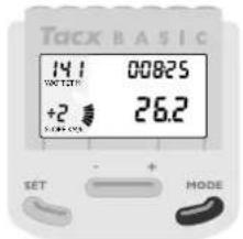
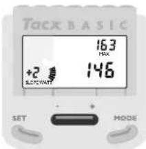
WATT (power)
By pressing the + key, at the bottom right of the display you will switch from speed to WATT, the actual power delivered (fig. 16).
CAD (Pedalling Frequency)
Pressing the + and - key again will switch from WATT to CAD at the bottom right of the display, the cadence or actual pedalling frequency (fig. 17).
14
15

16

17
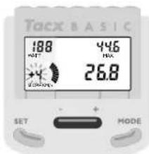
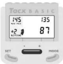
MODE functions with WATT
When the display shows the power function (WATT), other functions are available with the MODE key. The stop watch (ETM) continues to run. When you are in WATT mode, TRP, MAX and AVS refer to trip use, maximum and average power, respectively.
The term trip use requires some explanation. Before being reset or turned off, the computer uses the stop watch and delivered power to calculate the trip use in kilocalories (Kcal).
MODE functions with CAD
When the display is in the pedalling frequency mode (CAD), TRP, MAX and AVS refer to the total number of pedal revolutions during the trip, maximum and average pedalling frequency, respectively.
By experimenting with the + or - key of MODE, you can combine various data. Pressing the key once produces data quickly and accurately. In this way, you will soon get used to the computer. Within ten minutes, you will be able to locate combinations that you will find interesting or important.

flowchart
graph TD
    A["KM/h"] --> B["STOPwatch"]
    A --> C["Cycling distance"]
    A --> D["Total distance"]
    A --> E["MAX"]
    A --> F["AVS"]
    A --> G["Clock"]
    H["WATT"] --> I["STOPwatch"]
    H --> J["Trip use in Kcal"]
    H --> K["Maximum power"]
    H --> L["AVS"]
    H --> M["Clock"]
    N["CAD"] --> O["STOPwatch"]
    N --> P["Trip use in Kcal"]
    N --> Q["Maximum power"]
    N --> R["AVS"]
    N --> S["Clock"]
    T["MODE"] --> U["STOPwatch"]
    T --> V["Cycling distance"]
    T --> W["Total distance"]
    T --> X["AVS"]
    T --> Y["Clock"]
    Z["MODE"] --> AA["STOPwatch"]
    Z --> AB["Trip use in Kcal"]
    Z --> AC["Maximum power"]
    Z --> AD["AVS"]
    Z --> AE["Clock"]
    AF["MODE"] --> AG["STOPwatch"]
    AF --> AH["Trip use in Kcal"]
    AF --> AI["Maximum power"]
    AF --> AJ["AVS"]
    AF --> AK["Clock"]
    AL["MODE"] --> AM["STOPwatch"]
    AL --> AN["Trip use in Kcal"]
    AL --> AO["Maximum power"]
    AL --> AP["AVS"]
    AL --> AQ["Clock"]
    AR["MODE"] --> AS["STOPwatch"]
    AR --> AT["Trip use in Kcal"]
    AR --> AU["Maximum power"]
    AR --> AV["AVS"]
    AR --> AW["Clock"]
    AX["MODE"] --> AY["STOPwatch"]
    AX --> AZ["Trip use in Kcal"]
    AX --> BA["Maximum power"]
    AX --> BB["AVS"]
    AX --> BC["Clock"]
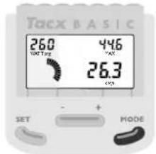
Slope (SET-function)
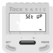
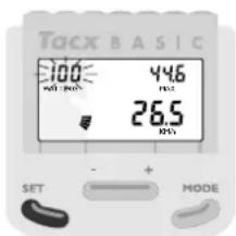
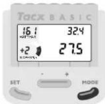
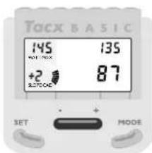
Now we will go a step further. The Basic also enables you to simulate resistance artificially. The Basic does this with SLOPE, the slope resistance factor. This resistance factor comes from the trainer's roller. The faster the roller turns, the easier it is for the computer to apply the brakes to the roller. At low speeds and low pedalling frequencies, it is more difficult for the Basic to brake the roller than it is at high speeds and high pedalling frequencies. For this reason, we have programmed fourteen steps in the SLOPE, from -4 to and including +9. The slope resistance factor for values exceeding nil depends on body weight.
By pressing the SET key, the slope resistance mode (SLOPE) will flash in the lower left-hand corner of the display (fig. 18). The default setting is 0. Using the + and - key, you can vary the slope resistance factor from -4 to and including +9 (fig. 19). By pressing the MODE key, you can then set a new slope resistance factor.

You might think that a slope resistance factor of +9 equals a slope angle of +9 degrees and a slope resistance factor of -4, with a slope angle of -4 degrees. Obviously, with a slope resistance factor of -4, the trainer will not descend if you stop pedalling. The steps from -4 to +9 are used to enable the trainer to make the proper resistance calculations and adjustments for the programmed power.
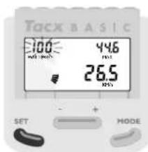
Programmed Power (SET-function)
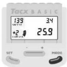
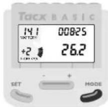
Finally, you can go a step further. After pressing the SET key, while the slope resistance mode is flashing (fig. 20), by pressing SET again the programmed power (WATT prg) will start to flash in the upper left-hand corner of the display (fig. 21). With programmed power, independent of pedalling speed and pedalling frequency, the computer attempts to adjust the resistance on the roller so that you are constantly producing the pedalling power you wanted and which you programmed. When you change pedalling frequency, the computer automatically adjusts the resistance on the roller, so you constantly produce the same power. If you change your own resistance, the computer follows suit, adjusting the resistance on the roller.
You can set the programmed power using the + and - key, in stages of 10 watts (fig. 22), when the WATT prg is flashing. The standard programmed power is 100 watts, but you can adjust it from 0 watts to and including 990 watts. Most cyclists, however, prefer to train with values between 100 and 400 watts.
18
19

20

21
After setting the programmed power, you can enter it by pressing the MODE key (fig. 23). Once the programmed power has been entered, the SLOPE value disappears as long as you are cycling in the WATT prg mode. The computer keeps track of the most recently programmed power, even after it has been turned off. To exit from the programmed power, you should press the SET key twice, which will put you back in the SLOPE mode.
Power (Watt) equals Effort times Speed
During cycling, the Basic will use SLOPE to adjust the power (watts) you programmed. Suppose, for example, you have programmed a power of 400 watts and you want to pedal this relatively high power, using relatively little effort (e.g. resistance 39 x 26) and a relatively low speed (e.g. a pedalling frequency of 70). The SLOPE cannot provide sufficient resistance to attain the programmed power. You will see that the WATT designation at the bottom right (actual power) does not agree with the programmed power (WATT prg).
WATT prg will start to flash at the upper left of the display (fig. 24) to indicate that you are outside the computer's field of operation. By adjusting your resistance (greater/heavier) and pedalling frequency (higher), you will soon find yourself returning to the computer's field of operation. WATT prg will then light up continuously.
Conversely, if you have programmed relatively low power and you attempt to attain it with relatively great effort (e.g. resistance 52 x 16) and a high speed (e.g. pedalling frequency of 100), the actual power will logically extend beyond the programmed power. Here, too, you will be outside the computer's field of operation, with WATT prg flashing in the upper left corner. Adjust acceleration and pedalling frequency until you reenter the computer's field of operation.

22
23
24
4 TRAINING RECOMMENDATIONS
Of all sports requiring a major physical effort from the athlete, cycling heads the list. Cycling is generally seen as the most physically difficult sport in terms of the pressure that heart, lungs and muscles are subjected to. For those using the Tacx Cycletrainers, the same holds true to a certain degree, especially since you want to increase the pressures you undergo. An extensive, annual medical checkup with a professional sports doctor is the first requirement before you start a new cycling season.
A possible definition of training could be “The systematic application of stimuli to improve performance”. We have a goal when we train. The goal could be to lose weight, to complete a particular sporting cycle on the bike or to win a gold medal during a championship race. The “stimuli” that we apply could consist of riding long distances at a steady pace, or sprinting short distances. It is important to build up the intensity of the training. As the season progresses, we ride longer, further or even cycle at altitude (in the mountains). When it comes to real improvement of performance, variation is the magic word.
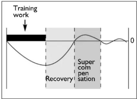
Super Compensation
When we train, we cause a disruption in the body. This disruption (of heart, lungs, muscles) recovers when we rest and improves slightly. We call this principle super compensation. It is not the training that makes us stronger; it is the rest period that follows. The subsequent training should take place just before the super compensation curve reaches the zero line (fig. 25). To raise one's physical fitness to a higher level, it is necessary to train a minimum of three times a week. Training twice a week is sufficient to retain one's physical fitness. Once a week is not enough. You can devise your own training schedule or have your coach or trainer do so.
During training with the Basic, it would be advisable to use a pulse meter.
Examples of Training Programmes
Always do warming-up exercises before you start training. Five or ten minutes of relaxed cycling with little resistance and a pedal frequency of between 90 and 110 revolutions per minute. During the warming-up period, you can do some stretching exercises (even on the bike). End the training with a cooling-down period of between five and ten minutes, again followed by some stretching exercises. Avoiding warming-up and cooling-down sessions could lead to injuries.
25
The Tacx Basic is very well equipped for specific training. Befor starting the trainingsprogramm it would be wise to test your physical health so that you know what power you can apply and what heartrates you have. Than prepare, e.g. with a trainer/coach, an annual training plan (year, month and week plan) set for your own goals, levels and possibilities. During the annual plan you train on the Basic throughout the seasons (so not only with bad weather). Power training makes you stronger, faster and better. You climb, sprint, work with a powertraining (see example) and simulate a time trial.
With the Basic it is also possible to do a “Conconi test”, the Astrandtest or the PWC test (Physical Work Capacity). The last two tests are available on our website. You will be able to ride them right after you have entered your personal data and you will see the results of the tests right away.

Training advice and the latest developments at the Tacx homepage: www.tacx.nl.
Recovery work-out
| Time(min) | Slope rpm Gear Details |
| 3 | 100 | lowest relaxed pedalling/high speed |
| 3 | 100 | heavier relaxed pedalling/high speed | |
| 3 | 100 | heavier relaxed pedalling/high speed | |
| 3 | 100 | heavier relaxed pedalling/high speed | |
| 3 | 100 | heavier relaxed pedalling/high speed | |
| 3 | 100 | lighter relaxed pedalling/high speed | |
| 3 | 100 | lighter relaxed pedalling/high speed | |
| 3 | 100 | lighter relaxed pedalling/high speed | |
| 3 | 100 | lighter relaxed pedalling/high speed | |
| 3 | 100 | lowest relaxed pedalling/high speed | |
| 36 | |
You might want to repeat this again on position 2 in 2 minutes each time and again on position 3 with 1 minute repeaters. For variation you could ride with pedal frequency 80, 90, 110 or 120.
Power work-out
| Time(min) Watt rpm Gear | Details | |||
| 3 | 80 | 80/90 | free | warming-up/relaxes pedalling |
| 4 | 140 | 100 lowest | increase speed | ||
| 3 | 180 | 100 lowest | increase speed | ||
| 2 | 200 | 100 lowest | increase speed again | ||
| | | 240 | 90 | lowest | increase speed even more |
| 3 | 80 | 120 lowest | relaxed pedalling | |
| 4 | 180 60 | heavy | low speed/ remain seated | |
| 3 | 200 | 70 | heavier | low speed/ remain seated |
| 2 | 220 | 80 | heavier | low speed/ remain seated |
| | | 260 70 | heavier | stand on pedals | |
| 5 | 80 | 80/90 | free | cooling-down |
| 31 | ||||
The power used in these kinds of training is easily adapted to the individual demands/skills of the rider. Do not start on a level that is too high for you and make sure you finish the ride. Only than will training be effective!!
Hill work-out
| Time(min) | Slope | rpm | Gear | Details |
| 4 | 2 | 80/90 | free | relaxed pedalling/constant speed |
| 3 | 3 | >80 | free | try to keep speed high |
| 1 | 7 | 60 | 53-14 | stand on pedals! |
| 5 | 1 | >100 | 42-16 | high pedal frequency |
| 2 | 5 | >80 | 53-15 | sit/stand every 30" |
| 2 | 6 | 90/100 | 42-16 | remain seated |
| 5 | 1 | 110/130 | 42-16 | high pedal frequency |
| 10 | 1 | free | free | cooling-down |
| 32 |
5 ERROR MESSAGES
| Failure | Potential problem | Solution |
| Trainer | ||
| 1 The arrangement of the Basic when the bike wobbles | 1 The CycleForce frame is not level2 The frame has not been assembled properly3 The bike does not fit properly in the frame4 The frame is not fully extended | 1 Place the trainer on a level floor2 Check whether all bolts and nuts are properly tightened3 Check whether the Tacx Quick-release skewer has been mounted4 Unfold frame completely |
| 2 Rubber from the bike tyre sticks to the roller | 1 The tyre pressure is too low2 The roller does not press properly against the tyre | 1 Check tyre pressure, minimal 6 atmosphere2 Turn role so that it presses solidly against the tyre |
| 3 The bike makes a lot of noise | 1 A profile tyre was installed2 There is a pebble (ticking) in the tyre | 1 Mount tyre with totally or partially smooth tyre profile2 Check tyre for damage |
Basic computer and mag unit
| 4 Display is difficult to read or illegible | 1 The ambient temperature is too low or too high | 1 Use Excel at ambient temperatures between 5°C and 35°C (40°F & 95°) |
| 2 The display does not have a good angle of view | 2 Adjust the display so that you can look directly at it | |
| 3 The computer is not properly connected to the mag unit | 3 Check the cable and the plug contacts in the computer and the mag unit. They could be dirty, oxidised or bent | |
| 4 Perspiration may have dama-ged the computer print plate | 4 The print plate should be replaced | |
| 5 The print plate of the mag5 unit is burned out | The print plate should be replaced | |
| 5 The display shows incorrect values | 1 There is an interruption in Basic while saving the values, for example, due to a power failure during training | 1 To reset the computer completely: Depress the SET key for five seconds while inserting the plug at the bottom of the computer. Then press the MODE key twice |
| Failure | Potential problem | Solution |
| 6 Cycling power seems less than shown on the display | 1 The mag unit does not brake properly or at all2 The mains voltage is too low3 Several magnets of the mag unit are loose due to having been dropped4 The print plate of the mag unit is burned out | 1 Check the cable and plug contacts in the computer and the mag unit. They could be dirty, oxidised or bent2 The Basic works properly between 220 and 230 V/50Hz.3 The lid of the mag unit should be replaced4 The print plate should be replaced |
| 7 Cycling power seems higher than shown on the display | 1 The bike chain is worn2 Tyre pressure is too low3 The mag unit is not yet warm4 The ambient temperature is too low | 1 Replace the chain2 Make sure the rear tyre pressure is good3 The mag unit will be warm after about three minutes of cycling4 Usethe Basic at ambient temperatures between 5^ and 35^ ( 40^ & 95^ ) |
| 8 The pedalling frequency remains zero | 1 The cadence sensor has not been connected or the magnet has fallen out of the magnet holder2 The sensor was installed out of range of the magnet3 There is a break in the cadence sensor cable4 The sensor plug is not connected properly to the mag unit | 1 Connect the sensor or install a good magnet2 Make sure, the distance between the sensor and the magnet is about 3 mm3 Connect a new sensor4 Check whether the plug is completely in the connection |
| 9 The cycle speed remains zero | 1 The speed impulses do not reach the computer2 The bike wheel does not reach the mag unit roller3 The speed sensor in the mag unit is defective | 1 Check the cable and the plug contacts in the computer and the unit. They could be dirty, oxidised or bent2 Adjust the mag unit with the adjustment knob, so that the tyres cannot slip3 A new print plate will have to be installed in the magnet unit |
6 TECHNICAL SPECIFICATIONS
Speed (Km/h or Mi/h)
Current speed
Kilometer or Miles per hour
0,1 to 99,9 Km/h or Mi/h
Stopwatch, cycling time
Capacity 8 hours, 59 minutes, 59 seconds
TRP trip distance
Capacity 999,9 Km or Mi
ODO total distance
Capacity 99.999,9 Km or Mi
MAX maximum speed
Capacity 99,9 Km or Mi per hour
AVS average speed
Capacity 99,9 Km or Mi per hour
Power (watt)
Current power
Capacity 2-999 watt
AVS average power
Capacity 999 watt
MAX maximum power
Capacity 999 watt
TRP trip use in Kcal
Capacity 999,9 Kcal
Pedalling frequency (cad)
Current pedalling frequency (cadence)
Capacity 0-250 pedal revolutions
per minute
AVS average pedalling frequency
Capacity 250 pedal revolutions per minute
MAX maximum pedalling frequency
Capacity 250 pedal revolutions per minute
TRP Pedal revolutions per trip
Capacity 99.999 pedal revolutions
Various
24-hour clock
Capacity 23 hours, 59 minutes and
59 seconds
SLOPE resistance
-4 to +9 in increments of 1
WATT, modifiable power
0-990 Watt in increments of 10
Temperature Range
5^ C to 35^ C (40°F to 95°)
EU DECLARATION OF CONFORMITY
In accordance with the EU Machinery Directive 93/68EU Appendix II A.
We, Technische Industrie Tacx BV, Rijksstraatweg 52, 2241 BW Wassenaar the Netherlands hereby declare that the machine described below both in its excel design and construction and in the version marketed by us conforms to the relevant safety- and health-related requirements of the appropriate EU Directive. This declaration shall cease to be valid if modifications are made to the machine without our approval.
Product: CycleForce
Type: Basic
Technical Data: 220 V AC 50 Hz
Applicable EU Directives:
EÜ Machinery Directive (89/392/EU), in version 93/68/EU - EU Low-Voltage Equipment
Directive (73/23/EU) - EU Directive on Electromagnetic Compatibility (89/336/EU), in version 93/31/EU.
Harmonised standards applied:
EN 50081-1: EN 55022 (1993) class B, EN 50082-1: EN 61000-4-2; EN 61000-4-3; EN 61000-
4-4; EN 61000-4-5 and EN 61000-4-6
It is ensured through internal measures that series-production units conform at all times to the requirements of current EU Directives and relevant standards.
Wassenaar, 23-09-2000
J.H.J. Tacx
7 WARRANTY PROVISIONS
Tacx products are manufactured in accordance with the highest quality standards. A warranty period of one (1) year from the date of purchase applies to manufacturing or material defects of all Tacx products. Save the sales slip, since that is your proof of purchase!
The warranty shall expire if the product shows clear evidence of the following:
I use for any purpose other than that for which it was intended
2 inexpert use, repairs or dismantling
3 damage due to accidents or neglect
4 damage to the computer's printer plate caused by perspiration and/or humidity
5 defects that occur during shipment or transport of the product
The warranty does not apply to parts subject to normal wear and tear (e.g. batteries).
Shipping Costs
- Shipping charges to a Tacx dealer or Tacx Service Centre are for the owner's account.
- Tacx Service Centre will carry out repairs and provide return shipping without charge.
Procedure
- If, during normal use, a product does not function properly for any reason whatsoever, return it to your dealer, along with proof of purchase (copy of the sales slip) and a completed service form. You can also ship it directly to the nearest Tacx Service Centre in your country. There is a list of Tacx Service Centres in the Tacx catalogue, the user's manual and at the Tacx web site.
- Follow the instructions for return shipments. The Tacx Service Centre will only accept return shipments accompanied with completed service forms.
- The Tacx Service Centre will repair or replace products covered by the warranty within 30 days, free of charge.
- Technische Industrie Tacx bv shall be the sole judge as to whether a product is covered by the warranty. If a product is not covered by the warranty, it will be repaired and the charges will be billed. If the cost of repair exceeds 50.00 Euro, you will receive a cost estimate in advance. After receiving your confirmation, the product will either be repaired or returned to you in its original state.
Instructions for return shipments
I Only send those parts of the Tacx product that require repair.
2 Repack everything carefully in the original packaging. Transport damage will be for your account.
3 Fill in the service form completely and clearly.
4 Include a copy of the sales slip.
5 Send the package prepaid - with optional insurance - to the
Liability
- Technische Industrie Tacx by reserves the right to modify, improve or to cease manufacturing any of its products without prior notification.
- Tacx by shall not be obligated to add new features or elements to previously sold products, even if said products are returned under cover of warranty.
- Tacx by may replace defective parts by equivalent parts of similar quality, if identical parts are not available.
- Tacx by will not accept liability whatsoever for direct, incidental or particular damages arising from or relating to the use of the products.
SERVICE FORM
Before shipping the product for repair, read the error messages in the accompanying user's manual and go through the FAQs on the web site. To be eligible for service, use this form and fill in all information clearly.
Name, Initials ....
Address ....
Postal Code ....
Town
Country
Telephone
Product: Tacx Basic
Date of Purchase....
Computer Serial Number ....
Receipt of Purchase (copy enclosed)? □ yes no
Warranty Expired? □ yes no
Description of complaint:
Other information for Tacx Service Centre ....
Puissance (watts) = Force x Vitesse 67
Super-compensation 68

natural_image
Simple line drawing of a mechanical lever with an arrow indicating motion (no text or symbols)2
3
natural_image
Mechanical component diagram showing a pulley and lever mechanism (no text or symbols)6

7

8
Conseils
2 RÉGLAGE UNIQUE DE L'ORDINATEUR DE BORD
7
8

9
3 UTILISATION DE L'ORDINATEUR DE BORD
10
11

12

13

MAX (vitesse maximale)
14

15
16
17
Puissance (watts) = Force x Vitesse
DÉCLARATION DE CONFORMITÉ CE
7 DISPOSITIONS DE GARANTIE


natural_image
Simple line drawing of a mechanical lever with an arrow indicating motion (no text or symbols)2
natural_image
Mechanical component diagram showing a pulley and lever mechanism (no text or symbols)6

7
8
Consejos

7

8

9
3 USO DEL ORDENADOR
10
11
12
13
flowchart
graph TD
    A["+"] --> B["KM/h"]
    B --> C["WAT"]
    C --> D["CAD"]
    D --> E["-"]
    E --> F["+"]
    F --> G["Square"]
    G --> H["Square"]
    H --> I["Square"]
    I --> J["Square"]
    J --> K["Square"]
    K --> L["Square"]
    L --> M["Square"]
    M --> N["Square"]
    N --> O["Square"]
    O --> P["Square"]
    P --> Q["Square"]
    Q --> R["Square"]
    R --> S["Square"]
    S --> T["Square"]
    T --> U["Square"]
    U --> V["Square"]
    V --> W["Square"]
    W --> X["Square"]
    X --> Y["Square"]
    Y --> Z["Square"]
    Z --> A
WATT (potencia)
14

15
16
17
20
21
natural_image
Simple line drawing of a mechanical lever with an arrow indicating motion (no text or symbols)2
natural_image
Mechanical component diagram showing a wheel and lever mechanism (no text or symbols)6

7
8
Suggerimenti
7

8

9
3 USO DEL COMPUTER
10

11

12

13
19
20
21
Apollo Bicycle Co Pty Ltd
116b Gordon Street, Gordon Park
Queensland 403
T + 61 - 73 35 73 |44
F + 61 - 73 35 73 177
E shayne@apollobikes.com
AUSTRIA
E info@cycleslambert.com
CZECH REP.
Universe agency
Neuzer Bicycle Company
Banomi LPT 5 - 2500 Esztergom
T + 36 - 33 415 395
F + 36 - 33 411 116
E neuzer@elender.hu
ITALY
Norex Italia s.r.l.
Viale S. Lazzaro, 21
36100 Vicenza
Ph. + 39 - 044 49 63 330
Fax: + 39 - 044 49 63 322
E: norexita@tin.it
POLAND
Velo Sp. z.o.o.
Ul. Pszczynska 305
44-100 Gliwice
T + 48 - 32 23 28 37 7
F + 48 - 32 23 28 38 0
E office@velo.com.pl
NORWAY
Deler A/S
Naeringspark, Tarngata 17
N-0511 Oslo
T + 47 - 23 05 13 70
F + 47 - 23 05 13 75
SLOVENIA
BV&S d.o.o.
Stopice 92 - 8322 Stopice
T + 386 - 733 70 450
F + 386 - 733 70 451
E info@capitol-fitness.com
SOUTH AFRICA
RFA Rodney Fowler Agencies
Unit no 4, Hi Tech Park
Cambridge Commercial Park
22 Witkoppen Road, Paulshof 2056
T + 27 - 11 807 52 82
F + 27 - 11 807 29 98
E info@rodneyfowler.co.za
SPAIN
Temoc
Avenida Gudari, S/N - P.O. Box 125
E info@intercycle.com
UK
Fisher Outdoor Leisure PLC
Unit 2 Haslemere Business Centre
Lincoln Way, Enfield
Middlesex ENI ITE
T + 44 - 020 8805 3088
F + 44 - 020 8805 8821
E tacx@fisheroutdoor.co.uk
USA
Ochsner International Inc.
246, Marquardt Drive - 60090-
6430 Wheeling, Illinois
T + 1 - 847 465 8200
F + I - 847 465 8282
E info@ochsnerusa.com
Important Notice
The addresses of the Tacx Service Centres indicate wholesale distributors or Tacx branch offices and do not sell directly to the public. When contacted for spare part purchases they might refer you to the closest retailer in your area.


- Advies
- EENMALIG INSTELLEN COMPUTER
- GEBRUIK COMPUTER
- WATT (vermogen)
- Hinweis
- EINMALIGES EINSTELLEN DES COMPUTERS
- Regenerationstraining
- INDEX
- I Assembling Basic
- Single computer adjustment
- Using the computer
- Training recommendations
- Technical specifications &
- Warranty
- Symbols Used
- Assembling the Trainer
- Tip
- Connecting the Basic Computer
- Adjusting speed settings
- Setting body weight
- Setting 24-hour clock
- MODE functions with Km/h (or Mi/h)
- ETM (Stop Watch)
- TRP (Cycling Distance)
- ODO (Total Distance)
- MAX (Maximum Speed)
- AVS (Average Speed)
- CLOCK
- MODE Key Reset Functions
- + and - Key Functions
- WATT (power)
- CAD (Pedalling Frequency)
- MODE functions with WATT
- MODE functions with CAD
- Slope (SET-function)
- Programmed Power (SET-function)
- Power (Watt) equals Effort times Speed
- Super Compensation
- Examples of Training Programmes
- TECHNICAL SPECIFICATIONS
- Speed (Km/h or Mi/h)
- Current speed
- TRP trip distance
- MAX maximum speed
- Power (watt)
- AVS average power
- TRP trip use in Kcal
- Pedalling frequency (cad)
- Current pedalling frequency (cadence)
- MAX maximum pedalling frequency
- Various
- Temperature Range
- EU DECLARATION OF CONFORMITY
- WARRANTY PROVISIONS
- The warranty shall expire if the product shows clear evidence of the following:
- Shipping Costs
- Procedure
- Instructions for return shipments
- Liability
- SERVICE FORM
- Conseils
- RÉGLAGE UNIQUE DE L'ORDINATEUR DE BORD
- UTILISATION DE L'ORDINATEUR DE BORD
- MAX (vitesse maximale)
- Puissance (watts) = Force x Vitesse
- DÉCLARATION DE CONFORMITÉ CE
- DISPOSITIONS DE GARANTIE
- Consejos
- USO DEL ORDENADOR
- WATT (potencia)
- Suggerimenti
- USO DEL COMPUTER
- Apollo Bicycle Co Pty Ltd
- AUSTRIA
- CZECH REP.
- Universe agency
- Neuzer Bicycle Company
- ITALY
- Norex Italia s.r.l.
- POLAND
- NORWAY
- Deler A/S
- SLOVENIA
- BV&S d.o.o.
- SOUTH AFRICA
- RFA Rodney Fowler Agencies
- SPAIN
- Temoc
- UK
- Fisher Outdoor Leisure PLC
- USA
- Ochsner International Inc.
- Important Notice
Brand : Tacx
Model : Basic Ergotrainer T1670
Category : Exercise bike