
DMR520 - Surveillance Camera Monacor - Free user manual and instructions
Find the device manual for free DMR520 Monacor in PDF.
| Product type | 4-channel Digital Video Recorder (DVR) |
| Brand | Monacor |
| Model | DMR520 |
| Power supply | DC 19V power adapter (included) |
| Video inputs | 4 BNC inputs (cameras) |
| Video outputs | 1 main monitor output, 1 call monitor output (CALL) |
| Audio inputs | 2 audio inputs (RCA) for models 1 and 2, 1 for model 3 |
| Audio output | 1 mono audio output (RCA) |
| Hard drive | 1 SATA/IDE hard drive bay (not included) |
| Connectivity | LAN port (Ethernet), USB port (models 1 and 2), D/V port (VGA) |
| Video formats | NTSC / PAL (switchable) |
| Main functions | Manual, scheduled, event (motion, alarm) recording; playback with slow motion, fast forward/reverse; digital zoom; multi-channel display; PTZ control |
| LED indicators | HDD, HDD Full, ALARM, TIMER, PLAY, REC |
| Dimensions (approx.) | Width 300 mm, Depth 250 mm, Height 60 mm |
| Weight (approx.) | 2.5 kg (without hard drive) |
| Maintenance and cleaning | Clean the device with a soft, dry cloth. Disconnect before cleaning. |
| Security | Keyboard lock function (MENU + ENTER) |
| Spare parts and repairability | Hard drive user-replaceable. Other parts: contact customer service. |
| General information | Power adapter included, user manual, AP software, cables and connectors included depending on model. |
Frequently Asked Questions - DMR520 Monacor
User questions about DMR520 Monacor
0 question about this device. Answer the ones you know or ask your own.
Ask a new question about this device
Download the instructions for your Surveillance Camera in PDF format for free! Find your manual DMR520 - Monacor and take your electronic device back in hand. On this page are published all the documents necessary for the use of your device. DMR520 by Monacor.
USER MANUAL DMR520 Monacor
natural_image
Black rectangular electronic device with a CD inside, showing its open lid and drive spout (no visible text or symbols)ENGLISH
Please read instructions thoroughly before operation and retain it for future reference.
The image shown above may differ from the actual product appearance.
TABLE OF CONTENT
1 FUNCTION .... 1
1.1. PACKAGE CONTENT ....1
1.2 FRONT PANEL....2
1.3 REAR PANEL 4
2 GETTING STARTED 6
2.1 GETTING STARTED 6
2.2 SYSTEM TIME SETUP....6
3. BASIC OPERATION .... 7
3.1 RECORDING....7
3.2 PLAYBACK....7
APPENDIX 1 INSTALL HDD....8
APPENDIX 2 PIN CONFIGURATION ...... 9
1 FUNCTION
1.1. PACKAGE CONTENT
| ITEMS Model 1 Model 2 Model 3 | Model 4 Model 5 | ||||
| Digital Video Recorder (DVR) | √ | √ | √ | √ | √ |
| Adapter and Power Cord | √ | √ | √ | √ | √ |
| CD Manual & Hard Copy Quick Start | √ | √ | √ | √ | √ |
| Free Licensed Software AP Disc | √ | √ | √ | √ | √ |
| Free Compact Disc (CD) | √ | - | - | - | √ |
| Screws * 4 | √ | √ | √ | √ | √ |
| DSUB PIN Connector | √ | √ | √ | √ | √ |
| IR Receiver & Transmitter - - - | √ √ | ||||
* Please check the package contents to make sure that you receive all accessories shown above.
1.2 FRONT PANEL
1) LED Indication
The following LEDs will be on when:
HDD: HDD is reading or recording
HDD Full: HDD is full.
ALARM: Once the alarm is triggered
TIMER: When timer recording is turned on
PLAY: Under playing status
REC: Under recording status
2) MENU
Press "MENU" button to enter the main menu.
3) ENTER / SET
- Press "ENTER" button to confirm the setting.
Press "SET" to change the position of the channel display.
Press up/down/left/right direction buttons to select the channel that you want to change.
Press “ | “ or “ “ to select the channel which You would like to show.
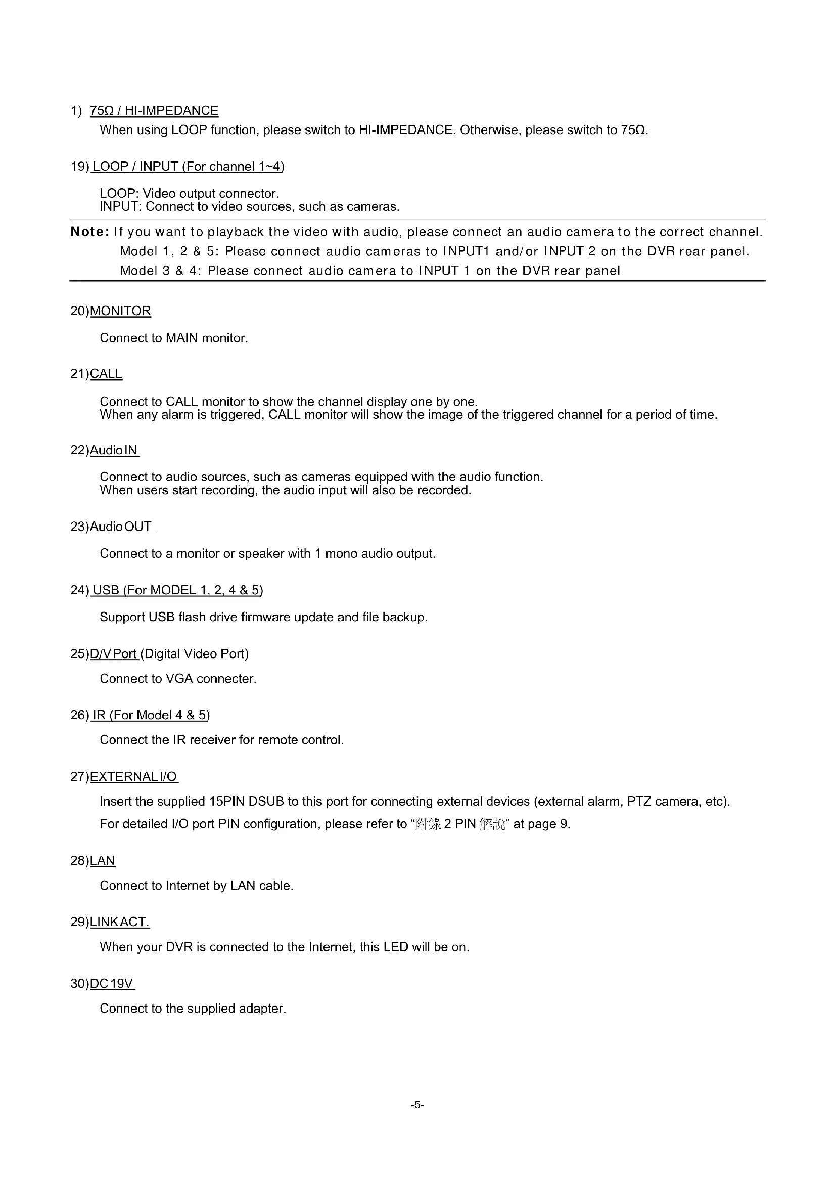
• Channel Display Position
Under the live mode, you can switch the positions of two channels in the following way:
Step1: Press "Set" to highlight one channel.
Step2: Press "UP", "DOWN", "LEFT", "RIGHT" button to move the highlight to the channel you want to change its position.
Step3: Press “ |” or “ ” to select the channel you want to switch its position with the one selected in Step2.
Step4: Press "ENTER" button to confirm the setting. For example, the position of CH2 & CH4 is switched as shown on the right side.
Under Live Mode
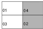
Under the playback mode, you can select a channel to display the live video instead of the playback video:
Step1: Press "Set" to highlight one channel.
Step2: Press "UP", "DOWN", "LEFT", "RIGHT" button to move the highlight to the channel you want to view the live video.
Step3: Press “+” or “−” to select the channel you want to view its live video.
Step4: Press "ENTER" button to confirm the setting. For example, CH2 playback view is replaced with CH4 live view as shown on the right side.
Under Playback Mode
4) SEARCH
Press "SEARCH" button to enter the search menu.
5) SLOW
Under the playback mode,
Model 1, 2 & 5: Press "SLOW" button to get 1/4X speed playback and press twice to get 1/8X speed playback.
Model 3 & 4: Press "SLOW" button to get 1/2X speed playback.
6) ZOOM
Press "ZOOM" button to enlarge the picture of selected channel (under the live mode).
7) 田一
Press "☐" button to show the 4 channel display modes.
Press “—” button to change the setting in the menu.
8) SEQ /+
Press "SEQ" button to activate the call monitor function, and press again to quit.
Press "+" button to change the setting in the menu.
9) (or POWER
Press this button long enough to turn on/off your DVR.
Note: Under the recording mode, please stop recording before turning off your DVR.
10) "CH1" "CH2" "CH3" "CH4"
Press one of the buttons to select the channel to display.
11)REC
Press "REC" button to activate manual recording.
12) or PLAY
Press this button to play the recorded video.
13) UP / PAUSE, DOWN / STOP, LEFT / REWIND, RIGHT / FORWARD,
Press one of the direction buttons to move the cursor up/down/left/right.
Under the playback mode:
Press “☐” or “☐” button to pause / stop playback. Press “◀” or “▶” button to fast rewind / forward.
SLOW ZOOM ↓AUDIO ↓ or (Audio)
Press these two buttons at the same time to select live or playback sounds of the audio channels.
15) or (PPTZ)
Press these two buttons at the same time to enter / exit the PTZ control mode.
In the PTZ control mode → Zoom in: Press "+" button ; Zoom out: Press "-" button
Adjust PTZ angle: Press direction buttons to turn up/down/left/right
Press “” or “POWER” button on the DVR front panel to shutdown the DVR.
After shutdown the DVR, press and hold (switch to NTSC) or (switch to PAL) first, then press the power button again to reboot the DVR (press until the monitor shows video images).
Note: The DVR will automatically detect PAL/NTSC system. But you can also manually switch between PAL and NTSC systems.
17)KeyLock
Press "MENU" + "ENTER" on the DVR front panel at the same time to lock keys and to log in with another user name.
18) Open / Close the CD Writer
For Model 1 and Model 5, press “▲” button to open / close the CD Writer.
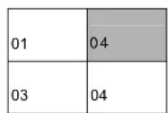
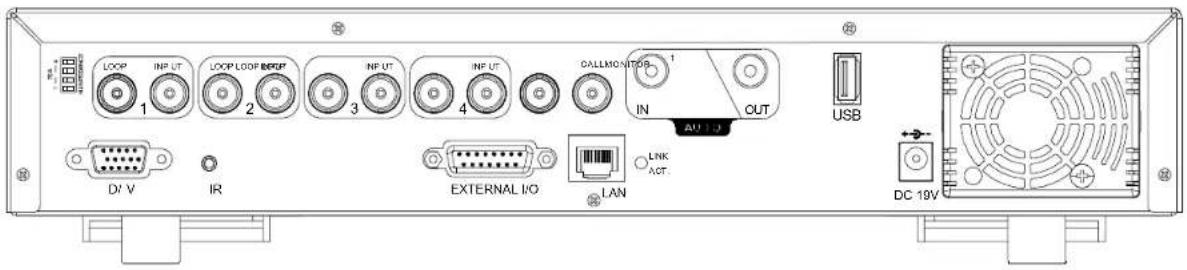
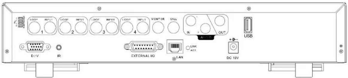
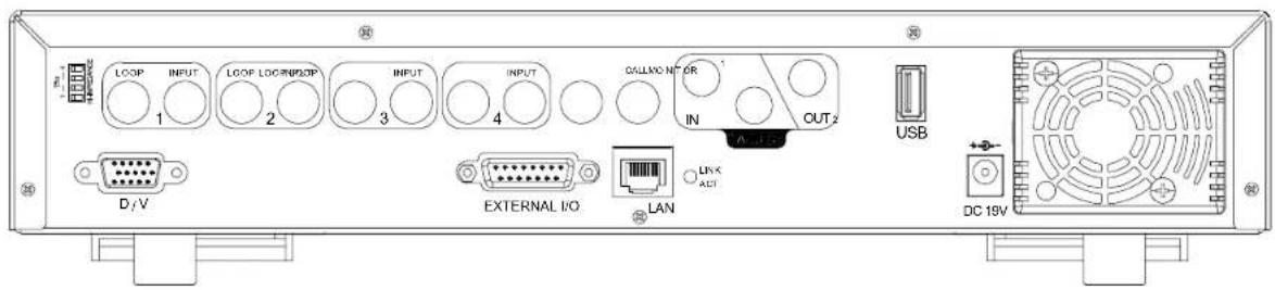
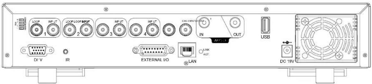
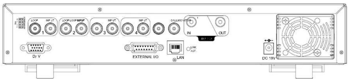
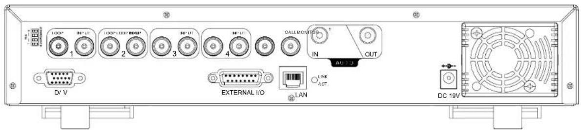
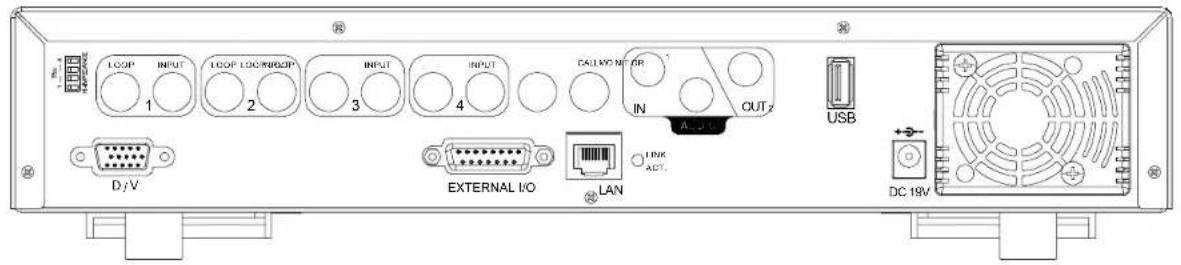
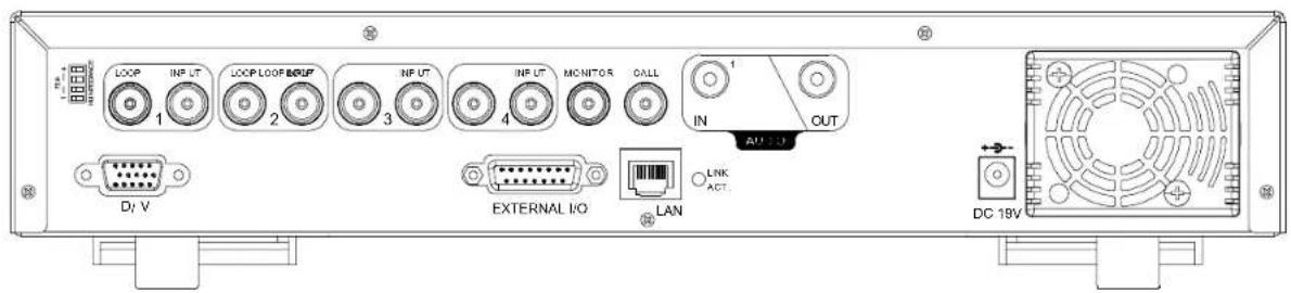
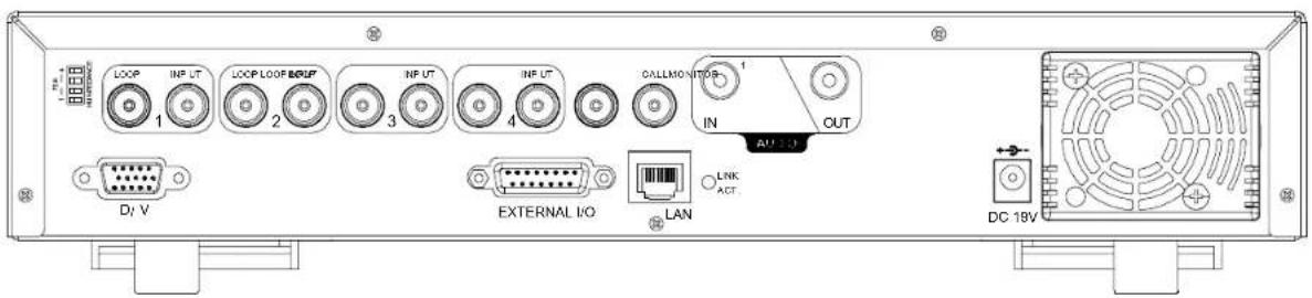
1.3 REAR PANEL
- MODEL 1
text_image
I OOR' INPUT 1 I OOR' I OOR/WBO? 2 3 4 INPUT INPUT CALLMONT OR IN 2 OUT A 175V USB D / V EXTERNAL KO LAN LINK ACT. DC 18V- MODEL 2

text_image
1 2 3 4 5 6 7 8 9 10 11 12 13 14 15 16 17 18 19 20 21 22 23 24 25 26 27 28 29 30 31 32 33 34 35 36 37 38 39 40 41 42 43 44 45 46 47 48 49 50 51 52 53 54 55 56 57 58 59 60 61 62 63 64 65 66 67 68 69 70 71 72 73 74 75 76 77 78 79 80 81 82 83 84 85 86 87 88 89 90 91 92 93 94 95 96 97 98 99 100- MODEL 3

text_image
LOOP INF UT 1 LOOP LOOP BEEP 2 INF UT 3 INF UT 4 DALLMONITOS IN OUT AUTO DI V EXTERNAL I/O LAN LINK ACT. DC 19V- MODEL 4
text_image
LOOP 1 INP UT 2 LOOP LOOP REGP 3 INP UT 4 INF UT OALLMONITOR 1 IN OUT USB DI V IR EXTERNAL I/O LAN LNK ACT. AU 1.0 DC 19V- MODEL 5
text_image
USB D:\V IR EXTERNAL NO LAN LINK ACT DC 19V1) 75Ω / HI-IMPEDANCE
When using LOOP function, please switch to HI-IMPEDANCE. Otherwise, please switch to 75Ω.
19) LOOP / INPUT (For channel 1\~4)
LOOP: Video output connector.
INPUT: Connect to video sources, such as cameras.
Note: If you want to playback the video with audio, please connect an audio camera to the correct channel.
Model 1, 2 & 5: Please connect audio cameras to INPUT1 and/or INPUT 2 on the DVR rear panel.
Model 3 & 4: Please connect audio camera to INPUT 1 on the DVR rear panel
20)MONITOR
Connect to MAIN monitor.
21)CALL
Connect to CALL monitor to show the channel display one by one.
When any alarm is triggered, CALL monitor will show the image of the triggered channel for a period of time.
22)Audio IN
Connect to audio sources, such as cameras equipped with the audio function.
When users start recording, the audio input will also be recorded.
23)Audio OUT
Connect to a monitor or speaker with 1 mono audio output.
Support USB flash drive firmware update and file backup.
25)D/VPort (Digital Video Port)
Connect to VGA connector.
26) IR (For Model 4 & 5)
Connect the IR receiver for remote control.
27) EXTERNAL I/O
Insert the supplied 15PIN DSUB to this port for connecting external devices (external alarm, PTZ camera, etc).
For detailed I/O port PIN configuration, please refer to "附錄 2 PIN 解說" at page 9.
28)LAN
Connect to Internet by LAN cable.
29)LINKACT.
When your DVR is connected to the Internet, this LED will be on.
30)DC 19V
Connect to the supplied adapter.
2.1 GETTING STARTED
Connect all the devices to construct a surveillance system.
- Install HDD:
The HDD must be installed before the DVR is turned on. Please refer to Appendix #1 for HDD installation instructions. - Connect cameras, monitors and external devices. Please refer to the section "1.3 REAR PANEL" for connection, and Appendix#2 for pin configurations of the external I/O port.
NOTE: Be sure the cameras are connected and power-supplied before the DVR is powered on. Otherwise the DVR will not be able to detect N/P system automatically.
- Connect the AC power cord to power adapter and plug into an electrical outlet.
The “” or “Power” LED will be on as red. Press the “” or “Power” button. The “” or “Power” LED will be on as green.
It takes approximately 10 to 15 seconds to boot the system.
- Set the date and time on your DVR. Please DO NOT change the date or time on your DVR after the recording function is activated. The recorded data will be disordered and you will not be able to find the recorded data to backup by time search.
NOTE: If users change the date or time accidentally when the recording function is activated, it's recommended to clear all HDD data, and start recording again.
2.2 SYSTEM TIME SETUP
Go to "MENU" mode, move the cursor to "DATE", and press "ENTER". The screen will show the following options.
Please DO NOT change the date or time when the recording function is activated. See "2.1 GETTING STARTED" at P.6 for details.
| MENU | DATE | |
| RECORD DATE 2006 TIMER FORMAT DATE ADVANCE | -DEC - 01 12 : 15 : 30 Y - M - D DAYLIGHT SAVING ON | |
| DAYLIGHT SAVING | ||
| START END ADJUST | 4TH-SUN-MAR TH-SUN-GCT 01:00 | 24:00:00 24:00:00 |
Set the start time and end time, and adjust the daylight saving time in hour. The above example means during the daylight-saving time period (starting from the 4th Sunday of March and ending on the 4th Sunday of October), the system time will plus one hour.
3. BASIC OPERATION
3.1 RECORDING
This device offers three recording modes: manual record, event record and timer record. If the power is off accidentally, the recorded video data will not be lost and is safely stored in the HDD. The device will return to the original recording status after the power is on again.
• MANUAL RECORD (continuous recording)
Recording is initiated by manually pressing "REC" button on the front panel.
This mode is indicated by the sign “●” on the screen.
• EVENT RECORD (triggered by motion and external alarm)
When this function is activated, the recording is triggered by motion or external alarms.
This mode is indicated by the sign " 🔊" (motion) or " 🔒" (external alarm) on the screen.
• TIMER RECORD (scheduled time)
Recording is scheduled by TIMER function.
Indicated by the wording "TIMER RECORD" on the monitor.
Please DO NOT change the date or time when the recording function is activated. See “2.1 GETTING STARTED” at P.6 for details.
3.2 PLAYBACK
Press “▶” or “PLAY” button on the front panel, and the device will display the last recorded video.
Note: There must be at least 8192 images of recorded data for playback to work properly. If not, the device will stop playback. For example, if the IPS is set to 30, the recording time should be at least 273 seconds (8192 images / 30 IPS) for the playback to work properly.
Playback related operations are described below:
- Fast Forward (11) / Fast Rewind (41)
You can increase the speed for fast forward and rewind on this device. In the playback mode:
Press “” once to get 4X speed forward and press twice to get 8X speed, etc. And the maximum speed is 32X.
Press “ once to get 4X speed rewind and press twice to get 8X speed, etc. And the maximum speed is 32X.
- Pause (II) / Image Jog
Press "button to pause the video playback.
In the Pause mode:
Press >>>button once to get one frame forward.
Press "<<button once to get one frame rewind.
- Stop ( )
Pressing "■" button under all circumstances will return this device to live monitoring mode.
• Channel Display Mode
Display mode:
Press "button to show the 4 channel display modes.
Full screen view:
Press one of the number buttons from 1-4 to show the selected channel in the full screen.
- Slow Playback
Model 1, 2 & 5: Press "SLOW" button to get 1/4X speed playback and press twice to get 1/8X speed playback. Model 3 & 4: Press "SLOW" button to get 1/2X speed playback.
• Audio
Press SLOW ZOOM or SLOW ZOOM buttons at the same time to select to play either live (L) or playback (P) sound.
AUDIO 1 (L) - 1^st audio channel, live audio;
AUDIO 1 (P) - 1^st audio channel, playback audio
AUDIO 2 (L) - 2^nd audio channel, live audio (Only Model 1, 2 & 5 have AUDIO 2 option)
AUDIO 2 (P) - 2^nd audio channel, playback audio (Only Model 1, 2 & 5 have AUDIO 2 option)
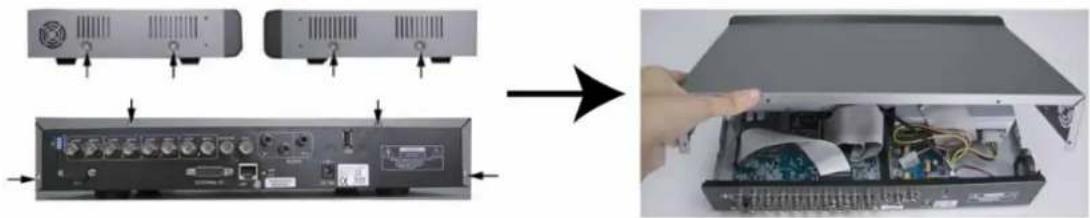
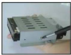
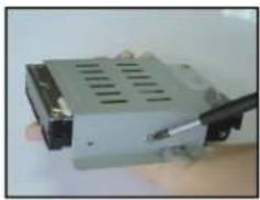
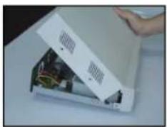
APPENDIX 1 INSTALL HDD
© HDD Installation for Model 1 and 5
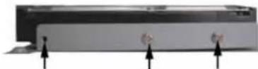
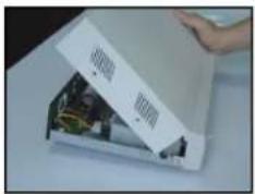
步骤1: Loosen the screws on the upper cover and open the upper cover of the DVR
natural_image
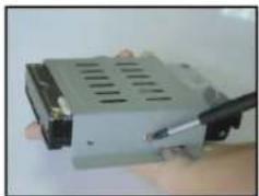
Diagram showing device ports and internal components being processed into a computer case (no text or symbols visible)1) Screw out the HDD bracket. For the positions of the HDD bracket screws, please refer to the figure below.
natural_image
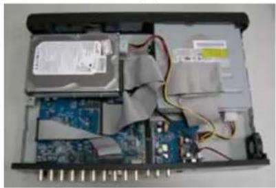
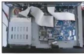
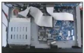
Interior view of an electronic device showing internal components like circuit boards, capacitors, and wiring (no visible text or labels)2) Get suitable brand HDD and set the HDD mode (Master / Slave) according to the indication.
3) Screw HDD onto the HDD bracket, two screws for each side. There are three screw holes per side on the bracket and you can choose two of them to secure the HDD. And then screw the HDD bracket back to the DVR base.
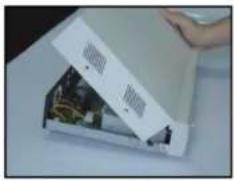
4) Connect the HDD to the power connector and IDE BUS (make sure to align the HDD precisely for pin connection). And then close the upper cover of the DVR and fasten all the screws you loosened in the step 1.
natural_image
Interior view of an electronic device showing internal components like CPU, memory, and wiring (no visible text or symbols)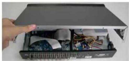
natural_image
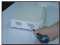
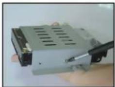
Interior view of an open electronic device with visible circuitry and wiring (no text or symbols)© HDD Installation for Model 2, 3 and 4
natural_image
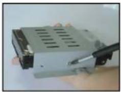
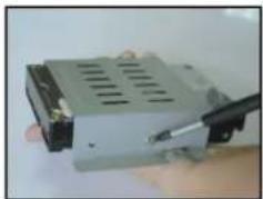
Hand holding a device with a label, no visible text or symbols on the device itselfFig. 1
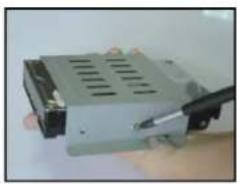
natural_image
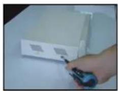
Close-up of a computer drive with a screwdriver inserted, no visible text or symbolsFig. 2
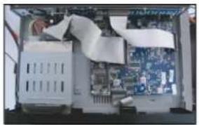
natural_image
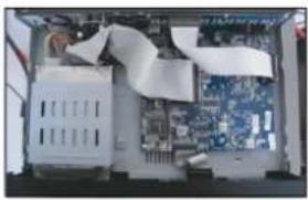
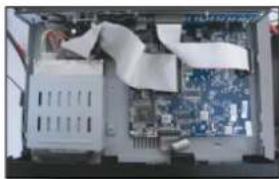
Interior view of a computer case with an open motherboard and a person working on it (no visible text or symbols)Fig. 3
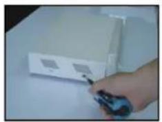
natural_image
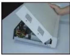
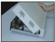
Hand opening a white rectangular box with internal electronic components (no visible text or symbols)Fig. 4
natural_image
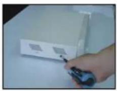
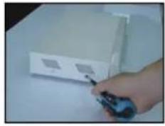
Hand holding a remote control device next to a white rectangular device (no visible text or symbols)Fig. 5
步骤2: Loosen the screws on the upper cover and open the upper cover of the DVR.
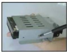
5) Screw out the HDD bracket.
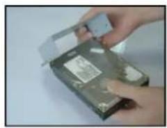
6) Get suitable brand HDD and set the HDD mode (Master or Single).
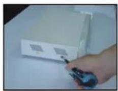
7) Screw HDD onto the HDD bracket, two screws for each side. And then screw the HDD bracket back to the DVR base. (Refer to Fig.1 & 2).
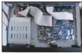
8) Connect the HDD to the power connector and IDE BUS (make sure to align the HDD precisely for pin connection) (Refer to Fig. 3)
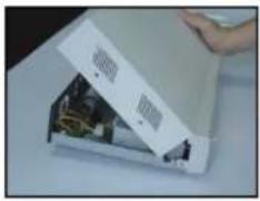
9) Close the upper cover of the DVR and fasten all the screws you loosened in the step 1. (Refer to Fig. 4 & 5)
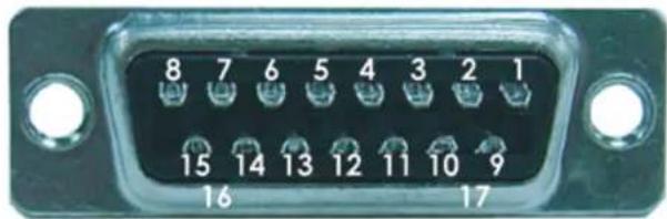
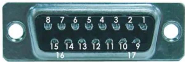
APPENDIX 2 PIN CONFIGURATION
Solder Side of DSUB 15 PIN
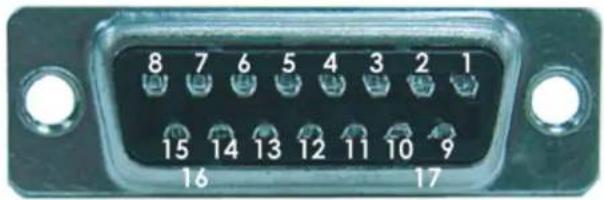
text_image
8 7 6 5 4 3 2 1 15 14 13 12 11 10 9 16 17| PIN FUNCTION | |
| 1 | RS232-TX |
| 2 | RS232-RX |
| 3 ~ 6 | ALARM INPUT |
| 7 | EXTERNAL ALARM NC |
| 8 | EXTERNAL ALARM NO. |
| 9 | GND |
| 10 | RS485-B |
| 11 | RS485-A |
| 12 ~ 13 | PIN OFF |
| 14 | ALARM RESET |
| 15 | EXTERNAL ALARM COM |
| 16 ~ 17 | GND |
4CH MPEG-4 DVR
快速安装指南

natural_image
Black rectangular electronic device with a CD or DVD slot, no visible text or symbols on the body.中文
11) “CH1” “CH2” “CH3” “CH4”
按其中一個按鍵來顯示該頻道畫面。
12) 錄影
按 “REC” 按鍵啟動手動錄影。
13) 或 PLAY
按此案件回放錄影影片。
text_image
LOOP INPUT LOOP LOOP/LOOP INPUT INPUT CALLMONT OR 1 2 3 4 IN OUT D:\V EXTERNAL I/O LAN LINK ACT DC 19V USB- MODEL 2
text_image
LOOP INPUT LOOP LOC#NDIP INPUT INPUT CALL#N OR OUT2 D/V EXTERNAL I/O LAN USB DC 18V- MODEL 3

text_image
LOOP 1 IN 2 LOOP LOOP BEEP 3 IN 4 IN 5 CALLMONITOR IN OUT DN V EXTERNAL I/O LAN LINK ACT DC 18V- MODEL 4
text_image
LOOP 1 INFL UT 2 LOOP LOOP BROUP 3 INFL UT 4 INFL UT CALL MOUNTED IN OUT USB D/V IR EXTERNAL I/O LAN LINK ACT DC 18V- MODEL 5

text_image
LOOP INPUT LOOP LOORPUT LOOPRUT INPUT MONITOR CALL IN 2 OUT USB 1 2 3 4 D/V IR EXTERNAL NO LAN LINK ACI DC 19V1) 75Ω / HI-IMPEDANCE
natural_image
Diagram showing device ports and internal wiring inside a device casing, with an arrow indicating transformation (no text or symbols present)natural_image
Interior view of an electronic device case with exposed circuit boards, capacitors, and wiring (no visible text or labels)natural_image
Interior view of an electronic device showing internal components like CPU, memory, and circuit board (no visible text or symbols)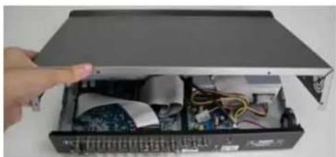
natural_image
Interior view of an open electronic device with visible circuitry and wiring (no text or symbols)natural_image
Hand holding a device with a small package, no visible text or symbols on the device itselfFig. 1
natural_image
Close-up of a computer drive with a pen inserted, no visible text or symbolsFig. 2
natural_image
Interior view of a computer room showing CPU socket, motherboard, and ventilation duct (no visible text or symbols)Fig. 3
natural_image
Close-up of a white electronic device with exposed internal components and a hand holding it (no visible text or symbols)Fig. 4
natural_image
Hand holding a remote control device next to a white electronic device (no visible text or symbols)Fig. 5
natural_image
Black rectangular electronic device with a white CD inside, showing its open lid and drive spout (no text or symbols visible)日本語
40) "CH1" "CH2" "CH3" "CH4"
text_image
LOOP INPUT LOOP LOG/RP/OP INPUT INPUT CALL/WC NT OR OUT 1 2 3 4 IN D/V EXTERNAL I/O LAN LINK ACT. USB DC 19V- MODEL 3
text_image
LOOP 1 INFL UT 2 LOOP LOOP/MPRUF 3 INFL UT 4 INFL UT CALLMONITOR IN OUT D/V EXTERNAL I/O LAN LINK ACT. AU 1.1J DC 18V14)75Ω / HI-IMPEDANCE
natural_image
Diagram showing device rear panel and internal electronics casing with a hand inserting into the case (no text or symbols visible)natural_image
Interior view of an electronic device showing internal components like circuit boards, capacitors, and wiring (no visible text or labels)natural_image
Interior view of an electronic device showing internal components like CPU, memory, and circuit board (no visible text or symbols)
natural_image
Interior view of an open electronic device showing internal components and wiring (no visible text or symbols)◎ Model 2 & Model 3
natural_image
Hand holding a device with a label, no visible text or symbols on the device itselfFig. 1
natural_image
Close-up of a computer RAM module being processed with a pen (no visible text or symbols)Fig. 2
natural_image
Interior view of a computer tower showing CPU socket, motherboard, and ventilation duct (no visible text or labels)Fig. 3
natural_image
Close-up of a white electronic device with exposed internal components and a hand holding the lid (no visible text or symbols)Fig. 4
natural_image
Hand holding a remote control device next to a white box (no visible text or symbols)Fig. 5
Solder Side of DSUB 15 PIN
text_image
8 7 6 5 4 3 2 1 15 14 13 12 11 10 9 16 17| PIN FUNCTION | |
| 1 | RS232-TX |
| 2 | RS232-RX |
| 3 ~ 6 | ALARM INPUT |
| 7 | EXTERNAL ALARM NC |
| 8 | EXTERNAL ALARM NO. |
| 9 | GND |
| 10 | RS485-B |
| 11 | RS485-A |
| 12 ~ 13 | PIN OFF |
| 14 | ALARM RESET |
| 15 | EXTERNAL ALARM COM |
| 16 ~ 17 | GND |
4CH MPEG-4 DVR
DEMARRAGE RAPIDE

natural_image
Black rectangular electronic device with a CD inside, showing its front panel and disc (no text or symbols visible)FRANCAIS
text_image
LOOP INPUT LOOP LOG/INPUT INPUT INPUT CALL/ON OR 1 2 3 4 IN OUT D/V EXTERNAL I/O LAN LINK ACT. USB DC 19V- Modèle 3
text_image
1 2 3 4 D/V 1 2 3 4 DALLMONITOR T IN OUT External I/O LAN LINK ACT DC 19V15)75Ω / HI-IMPEDANCE
Playback related operations are described below:
• Avance rapide (F.F. ▶) & rembobinage rapide (REW. ◀);
En mode relecture,
* AUDIO 1 (L) -- audio channel 1, audio direct
* AUDIO 1 (P) -- audio channel 1, relecture audio
* AUDIO 2 (L) -- audio channel 2, audio direct
* AUDIO 2 (P) -- audio channel 2, relecture audio
APPENDICE 1 - INSTALLER LE DD
© Modèle le 1 :
natural_image
Diagram showing device rear panel and internal circuit board with cable, no text or symbols presentnatural_image
Interior view of an electronic device showing internal components like CPU, memory, and wiring (no visible text or symbols)natural_image
Interior view of an electronic device showing internal components like CPU socket, memory card, and circuit board (no visible text or symbols)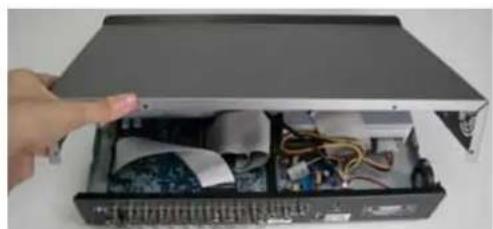
natural_image
Interior view of an open electronic device with visible circuitry and wiring (no text or symbols)Modèle le 2 & 3 :
natural_image
Hand holding a device with a small attached component, no visible text or symbolsFig. 1
natural_image
Close-up of a computer drive with a black cable inserted, no visible text or symbolsFig. 2
natural_image
Interior view of a computer motherboard showing CPU socket, motherboard, and drive bays (no visible text or labels)Fig. 3
natural_image
Close-up of a white electronic device with an open lid and internal components, being handled by a hand (no visible text or symbols)Fig. 4
natural_image
Hand holding a remote control device next to a white rectangular device (no visible text or symbols)Fig. 5
Solder Side of DSUB 15 PIN
text_image
8 7 6 5 4 3 2 1 15 14 13 12 11 10 9 16 17| PIN FUNCTION | |
| 1 | RS232-TX |
| 2 | RS232-RX |
| 3 ~ 6 | ALARM INPUT |
| 7 | EXTERNAL ALARM NC |
| 8 | EXTERNAL ALARM NO. |
| 9 | GND |
| 10 | RS485-B |
| 11 | RS485-A |
| 12 ~ 13 | PIN OFF |
| 14 | ALARM RESET |
| 15 | EXTERNAL ALARM COM |
| 16 ~ 17 | GND |
natural_image
Black rectangular electronic device with a CD inside, showing its open lid and drive spout (no text or symbols visible)DEUTSCH
98) "CH1" "CH2" "CH3" "CH4"
text_image
LOOP INPUT LOOP LOCK/BNOP INPUT INPUT CALL/KO NET IN OUT 1 2 3 4 D/FV EXTERNAL I/O LAN LAN USB DC 19V- Modell 3

text_image
LOOP 1 IN OUT CALLMONITOR 1 IN OUT LOOP 2 LOOP LOOP BBUF 3 4 D: V EXTERNAL I/O LAN LINK ACT DC-18Vnatural_image
Diagram showing device rear panel and internal circuit board with cable, no text or symbols presentnatural_image
Interior view of an electronic device casing with exposed circuit boards, wires, and components (no visible text or symbols)natural_image
Interior view of an electronic device showing internal components like CPU, memory, and circuit board (no visible text or symbols)
natural_image
Interior view of an open electronic device with visible circuitry and wiring (no text or symbols)Modell 2 & 3
natural_image
Hand holding a compact electronic device with a label, no visible text or symbols on the device itselfFig. 1
natural_image
Close-up of a computer RAM module with a screwdriver inserted (no visible text or symbols)Fig. 2

natural_image
Interior view of a computer tower showing CPU socket, motherboard, and cable rack (no visible text or labels)Fig. 3
natural_image
Close-up of a white electronic device with exposed internal circuitry and a hand holding the lid (no visible text or symbols)Fig. 4
natural_image
Hand holding a remote control device next to a white rectangular device (no visible text or symbols)Fig. 5
natural_image
Black rectangular electronic device with a CD inside, showing its open lid and drive spout (no text or symbols visible)ESPAÑOL
125) "CH1" "CH2" "CH3" "CH4"
text_image
LOOP INPUT LOOP LOOP INPUT INPUT CALLKONIF R 1 2 3 4 IN OUT D / V EXTERNAL I/O LAN LINK ACT. DC 18V USB- Modelo 2

text_image
LOOP INPUT LOOP LOOP/ROGDP INPUT INPUT CALL/VO N/BR IN OUT 1 2 3 4 D/FV EXTERNAL I/O LAN LINK ACT. USB DC 18V- Modelo 3

text_image
LOOP 1 IN OUT LOOP LOOP BBUF 2 3 4 IN INT IN D: V EXTERNAL I/O LAN LINK ACT DC 18Vnatural_image
Diagram showing device rear panel and internal circuit board with cable, no text or symbols presentnatural_image
Interior view of an electronic device with exposed circuit boards, wires, and components (no visible text or symbols)natural_image
Interior view of an electronic device showing internal components like CPU, memory, and circuit board (no visible text or symbols)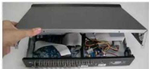
natural_image
Interior view of an open computer case with visible circuitry and wiring (no text or symbols)© Modelo 2 & 3
natural_image
Hand holding a small electronic device with a label, no visible text or symbols on the device itselfFig. 1
natural_image
Close-up of a computer hardware component with a screwdriver inserted, no visible text or symbolsFig. 2
natural_image
Interior view of a computer tower showing CPU socket, motherboard, and ventilation duct (no visible text or labels)Fig. 3
natural_image
Close-up of a hand opening a white electronic device with visible circuitry and components (no text or symbols)Fig. 4
natural_image
Hand holding a remote control device next to a white rectangular device (no visible text or symbols)Fig. 5
natural_image
Black rectangular electronic device with a CD inside, showing its front panel and disc (no text or symbols visible)PORTUGUÊS
The image shown above may differ from the actual product appearance.
ÍNDICE
1 FUNÇÕES....1
1.1. CONTEÚDO DA EMBALAGEM....1
1.2 PAINEL FRONTAL....2
1.3 PAINEL TRASERO 4
2 INICIAÇÃO....6
2.1 INICIAÇÃO ....6
2.2 AJUSTE DA HORA DE SISTEMA....6
3. OPERAÇÕES BÁSICAS......7
text_image
LOOP INPUT LOOP LOOP/INPUT INPUT INPUT CALL/ONIC R 1 2 3 4 IN OUT D / V EXTERNAL I/O LAN LINK ACT. DC 18V USB- Modelo 2
text_image
LOOP INPUT LOOP LOCK/INPUT INPUT INPUT CALL/WOT OR OUT 1 2 3 4 IN D/V EXTERNAL I/O LAN LINK ACT. USB DC 18V- Modelo 3
text_image
LOOP 1 IN OUT LOOP LOOP BBUF 2 3 4 INF UT INF UT MONITOR DALL IN OUT DN V EXTERNAL I/O LAN LINK ACT. DC 18V- Fast Forward (F.F.) / Fast Rewind (REW)
natural_image
Diagram showing device rear panel and internal circuit board with cable, no text or symbols presentnatural_image
Interior view of an electronic device showing internal components like circuit boards, cables, and connectors (no visible text or labels)natural_image
Interior view of an electronic device showing internal components like CPU, memory, and circuit board (no visible text or symbols)
natural_image
Interior view of an open electronic device with visible circuitry and wiring (no text or symbols)© Modelo 2 & 3
natural_image
Hand holding a device with a label, no visible text or symbols on the device itselfFig. 1
natural_image
Close-up of a computer drive with a black cable inserted, no visible text or symbolsFig. 2

natural_image
Interior view of a computer tower showing exposed circuit board and internal components (no visible text or symbols)Fig. 3

natural_image
Close-up of a white electronic device with exposed internal components and a hand holding the lid (no visible text or symbols)Fig. 4
natural_image
Hand holding a remote control device next to a white electronic device (no visible text or symbols)Fig. 5
9) Abra a tampa superior do DVR e desaparafuse o suporte.
natural_image
Black rectangular electronic device with a CD inside, showing its open lid and drive spout (no text or symbols visible)ITALIANO
179) "CH1" "CH2" "CH3" "CH4"
chemical
Chemical structure diagram showing two benzene rings with P.T.Z substituents, labeled 'oppure' and number 184text_image
LOOP INPUT LOOP LOCK/BNOP INPUT INPUT CALL/KO NET IN OUT 1 2 3 4 D/FV EXTERNAL I/O LAN LAN USB DC 19V- Modello 3
text_image
LOOP 1 IN OUT CALLMONITOR 1 IN OUT LOOP 2 LOOP LOOP BBUF 3 4 D: V EXTERNAL I/O LAN LINK ACT DC-18Vnatural_image
Diagram showing device rear panel and internal circuit board with a hand inserting a component (no text or symbols visible)natural_image
Interior view of an electronic device showing internal components like circuit boards, wires, and connectors (no visible text or symbols)natural_image
Interior view of an electronic device showing internal components like CPU, memory, and circuit board (no visible text or symbols)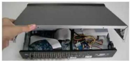
natural_image
Interior view of an open computer case with visible circuitry and a hand pointing to the lid (no text or symbols)© Modello 2 & 3
natural_image
Hand holding a device with a small white object attached, no visible text or symbolsFig. 1
natural_image
Close-up of a computer drive with a cable inserted, no visible text or symbolsFig. 2
natural_image
Interior view of a computer tower showing CPU socket, motherboard, and cable rack (no visible text or labels)Fig. 3

natural_image
Close-up of a white electronic device with a hand holding it, showing internal components and wiring (no visible text or symbols)Fig. 4

natural_image
Hand holding a remote control device next to a white electronic device (no visible text or symbols)Fig. 5