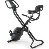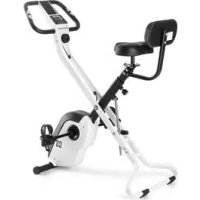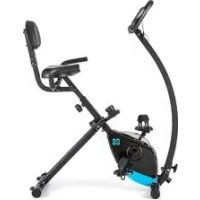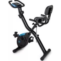
Azura 2 - Exercise bike Capital Sports - Free user manual and instructions
Find the device manual for free Azura 2 Capital Sports in PDF.


User questions about Azura 2 Capital Sports
0 question about this device. Answer the ones you know or ask your own.
Ask a new question about this device
Download the instructions for your Exercise bike in PDF format for free! Find your manual Azura 2 - Capital Sports and take your electronic device back in hand. On this page are published all the documents necessary for the use of your device. Azura 2 by Capital Sports.
USER MANUAL Azura 2 Capital Sports
text_image
QR code image containing encoded data, no visible human-readable textINHALTSVERZEICHNIS
Technische Daten 3
text_image
Technical diagram of a medical device with numbered components and labeled parts, likely for surgical or orthopedic identification.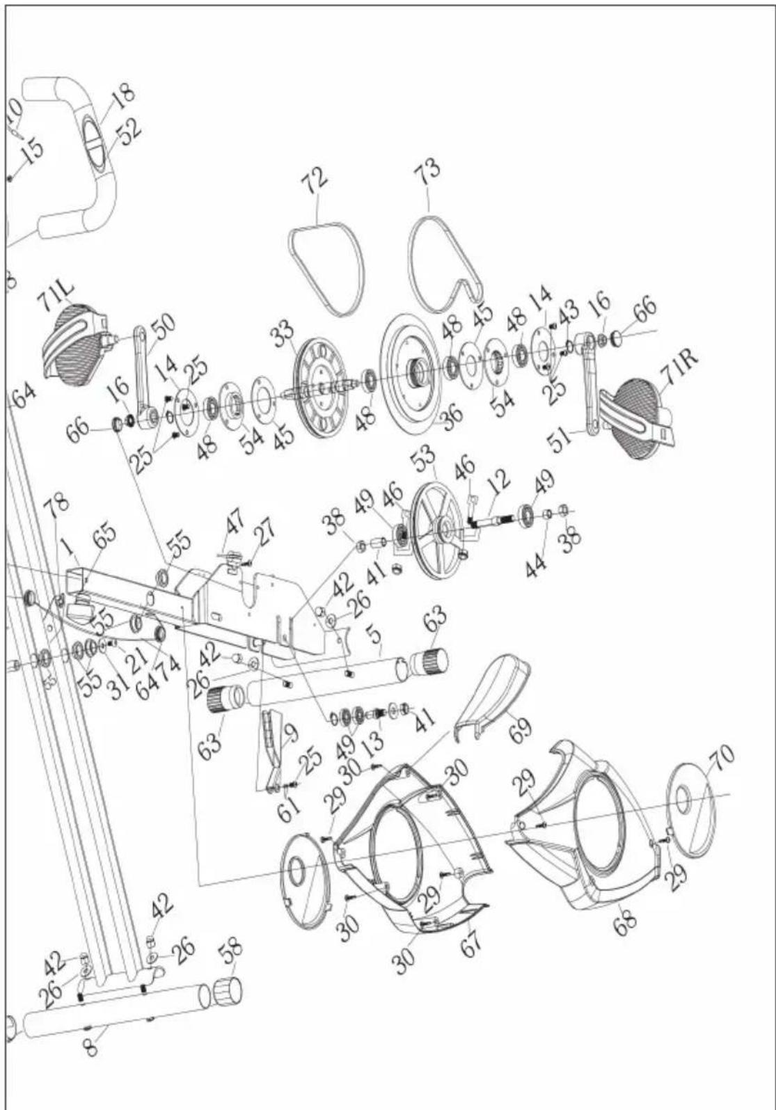
text_image
Technical diagram of a mechanical assembly with numbered components and exploded view, likely for assembly or manufacturing purposes.TEILE-LISTE
natural_image
Technical line drawing of a mechanical exercise device with articulated arms and levers (no text or symbols)text_image
Technical diagram of a mechanical device with labeled parts, including brackets and numbered components.text_image
Technical diagram of a stationary exercise machine with numbered components and labeled partstext_image
Technical diagram of a mechanical assembly with numbered components and labeled partsnatural_image
Technical line drawing of a two- Ebats exercise bike with adjustable arm and seat (no text or labels)natural_image
Symbol of a trash bin crossed with a diagonal line, no text or numbers presentBerlin Brands Group UK Ltd
PO Box 1145
Oxford, OX1 9UW
United Kingdom
Dear Customer,
Congratulations on purchasing this device. Please read the following instructions carefully and follow them to prevent possible damages. We assume no liability for damage caused by disregard of the instructions and improper use. Scan the QR code to get access to the latest user manual and more product information.
text_image
QR code image containing encoded data, no visible human-readable textCONTENT
Safety Instructions 26
Product Description 28
Part List 30
Hardware Packing List 33
Assembly Instructions 34
Operation 39
Operation Procedures 40
Functions 41
Care and Maintenance 42
Disposal Considerations 43
Manufacturer & Importer (UK) 43
TECHNICAL DATA
| Item number | 10026815, 10026816, 10026817, 10030579, 10037857, 10037858, 10037859, 10037860 |
| Power supply (console) | 2 x AAA batteries (included) |
SAFETY INSTRUCTIONS
Before operating this unit, please read this manual carefully to ensure optimum performance and safety. This is manual should be kept available for future reference. For product improvement, the company reserves the right to change the design and specification at any time without prior notice. Pictures are for reference use only and may differ from the actual product.
- Please keep this manual in a safe place for your reference when necessary.
- Please do not assembly or use this equipment until you read this manual thoroughly & carefully. The safety and efficiency only can be achieved when the equipment is assembled, maintained and used properly. It is your responsibility to ensure that all the users are informed of all the warnings and precautions.
- For totally safe use, a stable, leveled surface is required. Protect your floor with a mat. Do not use the equipment in a damp areas such as swimming pool sauna, etc. For safety space, the equipment must have at least 0.6 meter of free space all around it.
- Before starting any exercise program you must consult your doctor to determine if you have any physical or health conditions that could create a risk to your health and safety, or prevent you from using the equipment properly. Your doctor's advice is essential if you are taking medication that affects your heart rate, blood pressure or cholesterol level.
- Be aware of your body's signals. Incorrect or excessive exercise can damage your health. Stop exercising if you experienced any of the following symptoms: pain, tightness in your chest, irregular heartbeat, extreme shortness of breath, feeling light headed, dizzy or nauseous. If you do experience any of these conditions you must consult your doctor before continuing with your exercise program.
- Do not workout immediately after meals.
- Keep children and pets away from the equipment, the equipment must be assembled and used by adults only.
- The equipment is designed for home use only.
- The equipment is not suitable for therapeutic use, may only be used for exercises indicated in the training instructions
- Wearing proper clothing and athletic shoes while using the equipment, Avoid wearing loose clothing that may get caught in the equipment or that may restrict or prevent movements.
-
Keep your back straight while exercising.
-
Before using the equipment, check the handle bar, seat, and the nuts & bolts are securely tightened.
- For adjustable parts, bear the maximum position in your mind, do not exceed the mark „stop“, otherwise will cause risk.
- Always use the equipment as indicated. If you find any defective components while assembling or checking the equipment, or if you hear any unusual noises coming from the equipment during use, stop immediately. Do not use the equipment until the problem has been solved.
- Care must be taken when lifting or moving the equipment so as not to injure your back. always use proper lifting techniques and /or seek assistance if necessary.
- All moveable accessories(e.g. pedal, handlebar, saddle...etc.) require weekly maintenance. Check them before use every time. If anything broken or loose, please fix them immediately. You may continue using them only after they return to good conditions.
- Keep power cord away from heat sources.
- Do not insert or drop any object into any opening.
- Unplug exercise bike before moving or cleaning it. To clean, wipe surfaces down with mild detergents and a slightly damp cloth only; never use solvents.
- Do not use the exercise bike in any location that is not temperature controlled, such as, but not limited to, garages, porches, pool rooms, bathrooms, car ports or outdoors.
- Use the equipment only as described in this manual.
- Incorrect repair and structural modifications (e.g. removal or replacement of original parts) may endanger the safety of the user.
- This product is not designed for use by persons (including children) who have reduced physical, sensory or mental capacities or persons with no experience or knowledge, unless they are instructed and supervised in the use of the appliance by a person responsible for their safety.
- Children should be supervised to ensure that they do not play with the appliance.
- Before use, check the voltage on the device badge. Only connect the device to sockets that correspond to the voltage of the device.
Note: Maximum weight of the user is 100 kg.
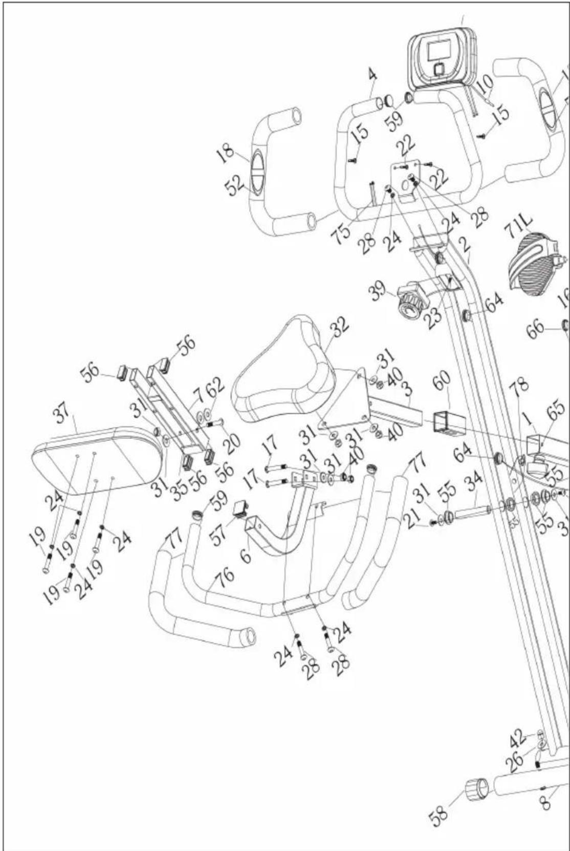
PRODUCT DESCRIPTION
text_image
Technical diagram of a medical device with numbered components and labeled parts, likely for surgical or orthopedic identification.
text_image
Technical diagram of a mechanical assembly with numbered components and exploded view, likely for assembly or manufacturing purposes.PART LIST
| No.DescriptionQty | ||
| 1 Main frame 1 | ||
| 2 Support rack 1 | ||
| 3 Seat-adjusting metal 1 | ||
| 4 Handle bar 1 | ||
| 5 Front Stablizer 1 | ||
| 6 Backrest elbow pipe 1 | ||
| 7 Backrest fixed pipe 1 | ||
| 8 Rear stabilizer 1 | ||
| 9 Magnetic board 1 | ||
| 10 Line of sensor 1 | ||
| 11 Computer | 1 | |
| 12 Alum idle wheel 1 | ||
| 13 Idle bearing 1 | ||
| 14 Bearing cover | 2 | |
| 15 Screw ∅4.2*15 2 | ||
| 16 Nut M10*P1.25 | 2 | |
| 17 Bolt M8*48 | 2 | |
| 18 Armrest foam 2 | ||
| 19 Screw M8*45 | 4 | |
| 20 Screw M8*76 1 | ||
| 21 Screw M8*15 | 2 | |
| 22 Screw M8*15 2 | ||
| 23 Screw M5*20 | 1 | |
| 24 Spring washer ∅8.2*10*1.5 | 6 | |
| 25 Screw M6*12 7 | ||
| 26 Spacer ∅8.2*∅20*1.5 R25 | 6 | |
| 27 Screw M4*10 1 | ||
| 28 Screw M8*40 2 | ||
| 29 Screw ST4.2*19 4 | ||
| 30 Screw ST4.2*20 4 | ||
| 31 Washer ∅8.2*∅20*1.6 10 | ||
| 32 Seat 5 | ||
| 33 Main belt wheel 4 | ||
| 34 Axis of rotation 1 | ||
| 35 EV mat 4 | ||
| 36 Flywheel ∅190*1.1kg 1 | ||
| 37 | Backrest | 1 |
| 38 | M10*P1.25nut | 2 |
| 39 | Eight period adjusting knob | 1 |
| 40 Nylon nut M8 5 | ||
| 41 | Pipe shrould | 1 |
| 42 | Cap nut M8 | 5 |
| 43 | External pliers ∅17 | 7 |
| 44 | Axis pipe | 1 |
| 45 | Bearing end cover reinforcement | 2 |
| 46 | Bolt M6 | 2 |
| 47 | Pressure sping | 1 |
| 48 Bearing 6003 4 | ||
| 49 Bearing 6000 2 | ||
| 50 | Left crank | 1 |
| 51 | Right crank | 1 |
| 52 | Pulse sensor | 2 |
| 53 | Alum belt plate 1 | |
| 54 | Bearing seat | 2 |
| 55 | Move bush | 6 |
| 56 | Tube plug 15*30 4 | |
| 57 | Tube plug 30*30 | 1 |
| 58 | Rear stabilizer bush | 2 |
| 59 Square head plug 4 | ||
| 60 Pipe bush 1 | ||
| 61 Wave washer ∅10*14*0.03 2 | ||
| 62 Nylon washer ∅9*∅20*2 2 | ||
| 63 Front wheel cover 2 | ||
| 64 Convenient plug 3 | ||
| 65 | Knob M12 | 1 |
| 66 | Crank cover | 2 |
| 67 | Left cover 1 | |
| 68 | Right cover | 1 |
| 69 | Front cover | 1 |
| 70 Small black cover 1 | ||
| 71 Pedal L/R 2 | ||
| 72 | Belt 240P 1 | |
| 73 Belt 230P 1 | ||
| 74 | Speed connecting line | 1 |
| 75 | Pulse connecting line | 1 |
| 76 | Rear handlebar set | 1 |
| 77 | Rear handlebar foam | 2 |
| 78 | Lock Pin | 1 |
HARDWARE PACKING LIST
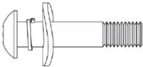 | 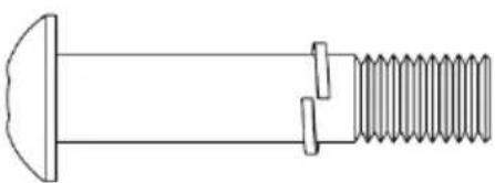 |
| #28 Screw M8*40#24 Spring washer ∅8.2*10*1.5#26 Spacer ∅8.2*∅20*1.5 R25 | #19 Screw M8*45#24 Spring washer ∅8.2*10*1.5 |
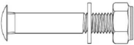 | 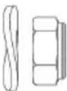 |
| #17 Bolt M8*48#31 Washer ∅8.2*∅20*1.6 #40Nylon nut M8 | #26 Spacer ∅8.2*∅20*1.5 R25#40 Nylon nut M8 |
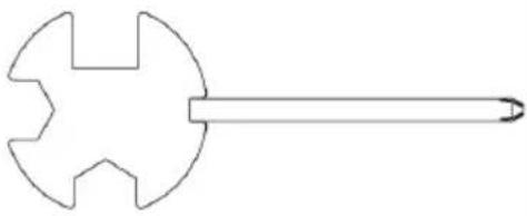 |  |
| Tightener Hex wrench |
ASSEMBLY INSTRUCTIONS
text_image
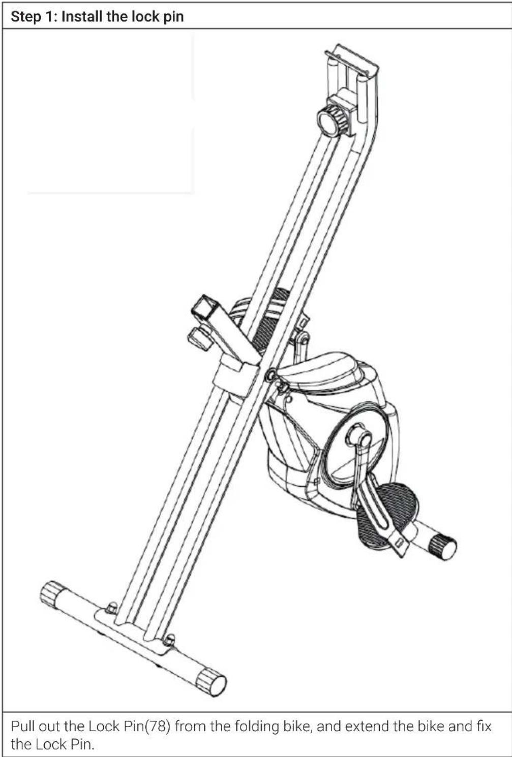
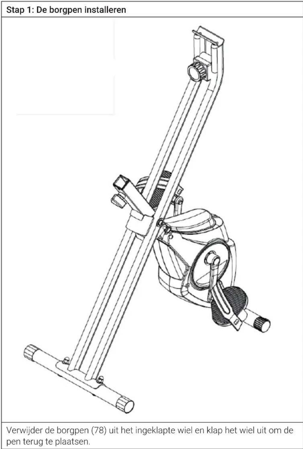
Step 1: Install the lock pin Pull out the Lock Pin(78) from the folding bike, and extend the bike and fix the Lock Pin.Step 2: Install the front and rear stabilizer
text_image
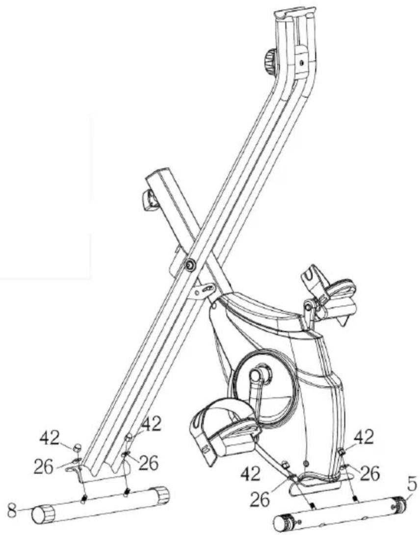
Technical diagram of a mechanical device with numbered components and labeled partsInstall front and Rear Stabilizer(5),(8) to Main Frame(1). Tighten hex nuts securely. Rear stabilizer has transport wheels. But you can use front or rear based on your preference.
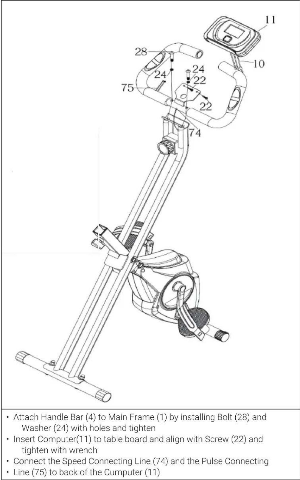
Step 3: Install the handlebar and computer
text_image
• Attach Handle Bar (4) to Main Frame (1) by installing Bolt (28) and Washer (24) with holes and tighten • Insert Computer(11) to table board and align with Screw (22) and tighten with wrench • Connect the Speed Connecting Line (74) and the Pulse Connecting • Line (75) to back of the Cumputer (11)Step 4: Install the Left and Right Pedal
- Note: Left Pedal installs counter clockwise. Install by rotating to LEFT. Use care that Pedal Shaft is Perpendicular to Crank Shaft. Use supplied wrench to tighten. Check pedals often for tightness when new.
- Note: Crank arms should be checked for tight-ness using 14mm socket after first couple hours of use.
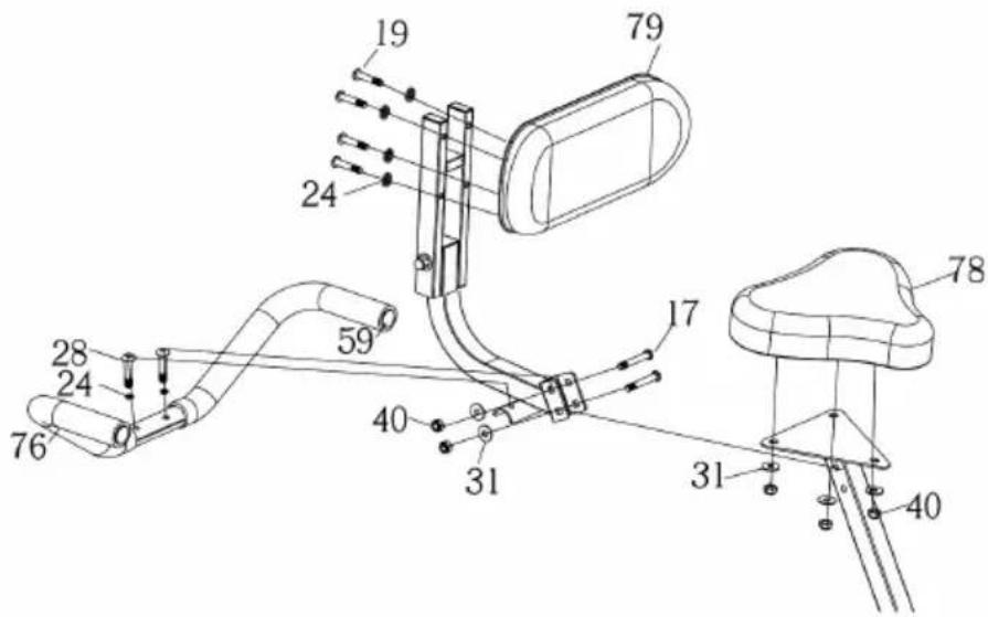
Step 5: Install the Saddle, Seat Back Cushion and the Back Handlebar
text_image
Technical diagram of a mechanical assembly with numbered components and directional arrows indicating motion or assembly.- Saddle (78) is mounted to Seat adjusting Metal (3) using Nylon nut M8 (40) and Washer (31).
- Align Bolt (28) with hole of Rear Handlebar Set (76), through Washer (24) and tighten securely.
- Align Bolt (19) with the hole of assembled seat back cushion(79), through Washer
• (24) and Nylon Nut (40) and tighten securely. - Back rest is connected with the seat tightly through Nylon Nut (40), Washer (31) and Bolt (17).
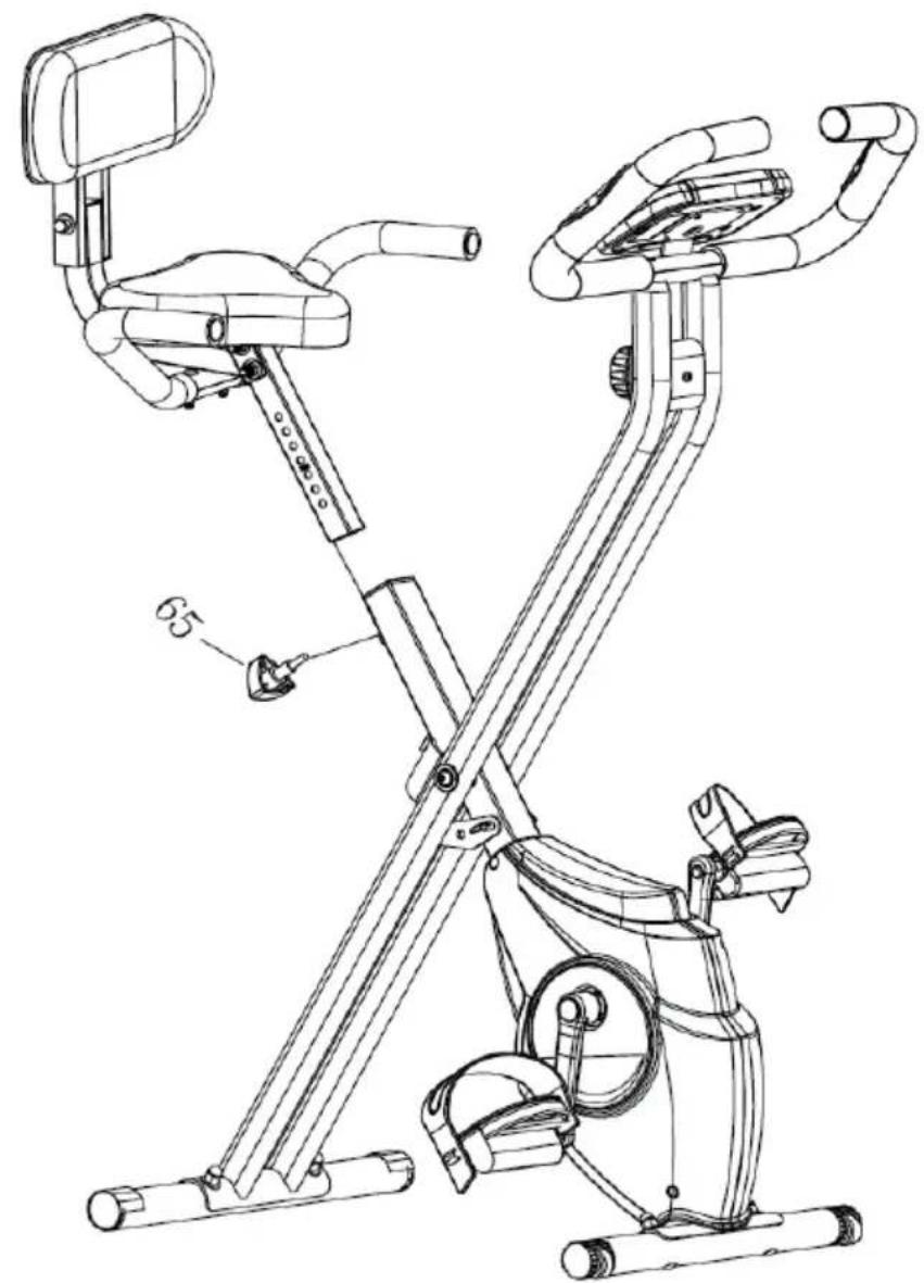
Step 6: Install the Seat Post to the Main frame
natural_image
Technical line drawing of a two- Ebats exercise bike with adjustable arm and seat (no text or labels)- Attach the seat post to the main frame, choose a suitable height, and then fasten the seat adjusting knob(65)
- Note: When adjusting the height of seat post, the maximum insert depth of mark line cannot be higher than the edge of bushing.
OPERATION
| Time (TIME) 00:00 - 99:59 | |
| Speed (SPD) 0 - 99.9 km/h (mph) | |
| Distance (DIST) 0 - 999.9 km (mi) | |
| Calorie (CAL) 0 - 9999 kcal | |
| Odometer (ODO) 0 - 999.9 km (mi) | |
| Pulse (PUL) 40 - 240 BPM | |
| Key Functions |
Key Functions
| MODE/SELECT/RESET This | key lets you to select and lock on to a particular function you want. |
| SET Can to proceed the data | establish for “TIME”“DISTANCE” “CALORIES”. |
| RESET The key to reset the value to zero by pressing the key. | |
The system turns on when any key is pressed or when it sensor an input from the speed sensor.
The system turns off automatically when the speed has no signal input or on key are pressed for approximately 4 minutes.
2. RESET
The unit can be reset by either changing battery or pressing the MODE key for 3 seconds.
3. MODE
To choose the SCAN or LOCK if you do not want the scan mode, press the MODE key when the pointer on the function you want which begins blinking.
FUNCTIONS
TIME:
Press the MODE key until pointer lock on to TIME. The total working me will be shown when starting exercise.
SPEED:
Press the MODE key until the pointer advanced to SPEED. The current speed will be shown.
DISTANCE:
Press the MODE key until the pointer advanced to DISTANCE. The distance of each workout will be displayed.
CALORIE:
Press the MODE key until pointer lock on to CALORIE. The calorie burned will be displayed when displayed will be shown.
ODOMETER (IF HAVE):
Press the MODE key until the pointer advanced to ODEMETER. The total accumulated distance will be shown.
PULSE (IF HAVE):
Press the MODE key until the pointer advance to PULSE, User's current heart rate will be displayed in beats per minute. Place the palms of your hands on both of the contact parts (or put ear-clip to ear), and wait for 30 seconds for the most accurate reading.
SCAN:
Automatically display changes every 4 seconds.
BATTERY:
If improper display on monitor, please reinstall the batteries to have a good result.
CARE AND MAINTENANCE
Note: As with all training machines with mechanical, moving components, screws may loosen due to frequent use. We therefore recommend that you check them regularly and, if necessary, retighten them with a suitable key. Clean your training device regularly with a damp cloth to clean the surfaces from sweat and dust.
- Often clean the exercise bike with clean cloth to keep the clean appearance.
- The safety level of the equipment only can be maintained if it is regularly examined for damage and or /wear and tear.(e.g. handle bar, pedals and seat ...etc.).It is vital that any faulty parts are replaced and the it is not used until completed repaired.
- Regularly check that the elements fastened with nuts and bolts are correctly tightened.
- Remember regularly to grease moving parts.
- Special attention to the component, most of them are susceptible to wear like brake system, foot pad etc.
- As sweat is very corrosive, do not allow it to come into contact with the enameled or chromed parts of the equipment, particularly the computer. Immediately wipe the equipment after using. The enameled parts can be cleaned using a damp sponge. All aggressive or corrosive products must be avoided.
- Storing the equipment in a clean and dry environment away from children.
DISPOSAL CONSIDERATIONS
natural_image
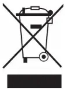
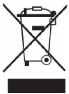
Symbol of a trash bin crossed with a diagonal line, no text or numbers presentIf there is a legal regulation for the disposal of electrical and electronic devices in your country, this symbol on the product or on the packaging indicates that this product must not be disposed of with household waste. Instead, it must be taken to a collection point for the recycling of electrical and electronic equipment. By disposing of it in accordance with the rules, you are protecting the environment and the health of your fellow human beings from negative consequences. For information about the recycling and disposal of this product, please contact your local authority or your household waste disposal service.
This product contains batteries. If there is a legal regulation for the disposal of batteries in your country, the batteries must not be disposed of with household waste. Find out about local regulations for disposing of batteries. By disposing of them in accordance with the rules, you are protecting the environment and the health of your fellow human beings from negative consequences.
MANUFACTURER & IMPORTER (UK)
Manufacturer:
Chal-Tec GmbH, Wallstrasse 16, 10179 Berlin, Germany.
Importer for Great Britain:
Berlin Brands Group UK Ltd
PO Box 1145
Oxford, OX1 9UW
United Kingdom
Estimado cliente:
text_image
QR code image containing encoded data, no visible human-readable textÍNDICE DE CONTENIDOS
text_image
Technical diagram of a mechanical device with numbered components and labeled parts in Chinese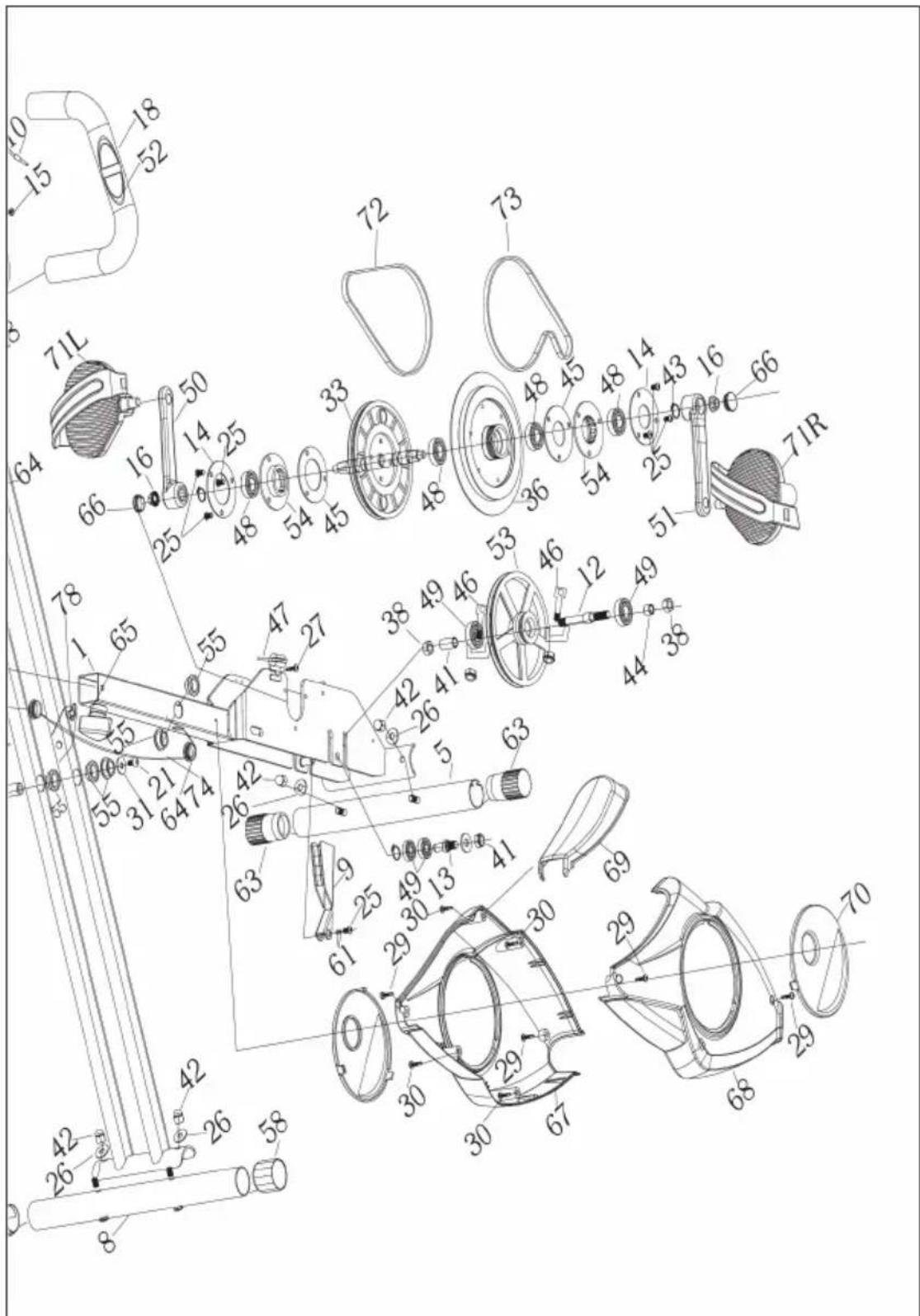
text_image
Technical diagram of a mechanical assembly with numbered components and exploded view, likely for assembly or manufacturing purposes.LISTA DE PARTES
natural_image
Technical line drawing of a mechanical device with articulated arms and a central rotating component (no text or symbols)text_image
Technical diagram of a mechanical device with numbered components and labeled partstext_image
Technical diagram of a mechanical or electrical assembly with numbered components and labeled partsnatural_image
Technical line drawing of a two- Ebats exercise bike with adjustable arm and seat (no text or labels)natural_image
Symbol of a trash bin crossed with a diagonal line, representing no waste or discharge (no text or labels)Berlin Brands Group UK Ltd
PO Box 1145
Oxford, OX1 9UW
United Kingdom
Cher client,
text_image
QR code image containing encoded data, no visible human-readable textSOMMAIRE
text_image
Technical diagram of a medical device with numbered components and labeled parts, likely for surgical or orthopedic identification.
text_image
Technical diagram of a mechanical assembly with numbered components and exploded view, likely for assembly or manufacturing purposes.LISTE DES PIÈCES DÉTACHÉES
natural_image
Technical line drawing of a mechanical exercise device with articulated arms and levers (no text or symbols)text_image
Technical diagram of a mechanical device with numbered components and labeled partstext_image
Technical diagram of a mechanical assembly with numbered components and labeled partsnatural_image
Technical line drawing of a two- Ebats exercise bike with adjustable arm and seat (no text or labels)natural_image
Symbol of a trash bin crossed with a diagonal line, no text or numbers presentBerlin Brands Group UK Ltd
PO Box 1145
Oxford, OX1 9UW
United Kingdom
Gentile Cliente,
text_image
QR code image containing encoded data, no visible human-readable textINDICE
Dati tecnici 85
text_image
Technical diagram of a medical device with numbered components and labeled parts for identification.
text_image
Technical diagram of a mechanical assembly with numbered components and exploded view, likely for assembly or manufacturing purposes.LISTA DELLE PARTI
natural_image
Technical line drawing of a mechanical exercise machine with articulated arms and levers (no text or symbols)text_image
Technical diagram of a mechanical device with numbered components and labeled partstext_image
Technical diagram of a mechanical assembly with numbered components and labeled partsnatural_image
Technical line drawing of a two- Ebats exercise bike with adjustable arm and seat (no text or labels)natural_image
Symbol of a trash bin crossed with a diagonal line, no text or labels presentPRODUTTORE E IMPORTATORE (UK)
Produttore:
Chal-Tec GmbH, Wallstraße 16, 10179 Berlino, Germania.
Berlin Brands Group UK Ltd
PO Box 1145
Oxford, OX1 9UW
United Kingdom
Geachte klant,
text_image
QR code image containing encoded data, no visible human-readable textINHOUDSOPGAVE
text_image
Technical diagram of a medical or laboratory device with numbered components and labeled parts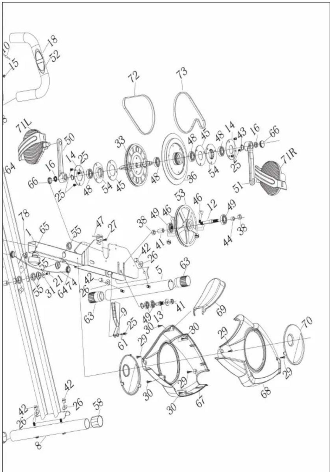
text_image
Technical diagram of a mechanical assembly with numbered components and exploded view, likely for assembly or manufacturing purposes.LIJST VAN ONDERDELEN
| Nr.BetekenisAantal | ||
| 1 Basisframe 1 | ||
| 2 Ondersteunend frame 1 | ||
| 3 Zadel (verstelbaar) 1 | ||
| 4 Stuur 1 | ||
| 5 Stabilisator vooraan 1 | ||
| 6 Buis rugleuning 1 | ||
| 7 | Bevestiging rugleuning 1 | |
| 8 Stabilisator achteraan 1 | ||
| 9 | Magnetisch wiel | 1 |
| 10 Sensorleiding | 1 | |
| 11 | Computer | 1 |
| 12 | Vrijloopwiel | 1 |
| 13 Bedekking | 1 | |
| 14 | Bedekkingsbescherming | 2 |
| 15 | Schroef ∅4.2*15 | 2 |
| 16 | Moer M10*P1.25 | 2 |
| 17 | Bout M8*48 | 2 |
| 18 Vulling armleuning | 2 | |
| 19 | Schroef M8*45 | 4 |
| 20 | Schroef M8*76 | 1 |
| 21 | Schroef M8*15 | 2 |
| 22 | Schroef M8*15 | 2 |
| 23 | Schroef M5*20 | 1 |
| 24 | Onderlegring ∅8.2*10*1.5 6 | |
| 25 | Schroef M6*12 | 7 |
| 26 | Plaatshouder ∅8.2*∅20*1.5 R25 | 6 |
| 27 | Schroef M4*10 | 1 |
| 28 | Bout M8*40 | 2 |
| 29 Schroef ST4.2*19 4 | ||
| 30 Schroef ST4.2*20 4 | ||
| 31 Bijlage ∅8.2*∅20*1.6 10 | ||
| 32 Zitting 5 | ||
| 33 Hoofdwietje 4 | ||
| 34 Rotatie-as 1 | ||
| 35 | EV mat | 4 |
| 36 Vliegwiel ∅190*1.1kg 1 | ||
| 37 | Rugleuning | 1 |
| 38 | M10*P1.25 moer 2 | |
| 39 | Afstelwiel | 1 |
| 40 | Nylon moer M8 | 5 |
| 41 | Buisbescherming | 1 |
| 42 | Moerdop M8 | 5 |
| 43 | Tang ∅17 7 | |
| 44 | Lange as buis | 1 |
| 45 | Bedekking en bescherming | 2 |
| 46 | Pin M6 | 2 |
| 47 | Druk spin | 1 |
| 48 | Bedekking 6003 | 4 |
| 49 | Bedekking 6000 | 2 |
| 50 | Hendel links | 1 |
| 51 | Hendel rechts 1 | |
| 52 | Polssensor | 2 |
| 53 | Riemplaat 1 | |
| 54 | Zitbekleding | 2 |
| 55 | Beweging bekleding | 6 |
| 56 Buisbekleding 15*30 4 | ||
| 57 Buisbekleding 30*30 1 | ||
| 58 | Rugstabilisator voering | 2 |
| 59 Dwarssluiting 4 | ||
| 60 Buisbekleding 1 | ||
| 61 Golven plaatshouder ∅10*14*0.03 2 | ||
| 62 Nylon plaatshouder ∅9*∅20*2 2 | ||
| 63 Voorwielafdekking 2 | ||
| 64 Sluiting 3 | ||
| 65 Afstelwiel M12 | 1 | |
| 66 | Hendel bescherming | 2 |
| 67 | Bescherming links | 1 |
| 68 | Bescherming rechts | 1 |
| 69 | Voorkant bescherming | 1 |
| 70 | Kleine zwarte bescherming | 1 |
| 71 | Pedaal L/R | 2 |
| 72 | Riem 240P | 1 |
| 73 | Riem 230P | 1 |
| 74 | Snelheidverbindingskabel | 1 |
| 75 | Pols aansluitkabel 1 | |
| 76 | Handgrepen set | 1 |
| 77 | Handvat bekleding | 2 |
| 78 | Borgpen | 1 |
OVERZICHT VAN DE AFZONDERLIJKE ONDERDELEN
 | 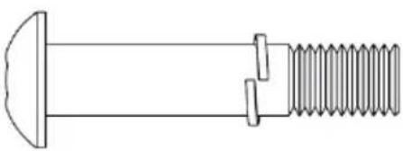 |
| #28 schroef M8*40#24 spring washer ∅8.2*10*1.5#26 Onderlegschijf ∅8.2*∅20*1.5R25 | #19 Schroef M8*45#24 spring washer ∅8.2*10*1.5 |
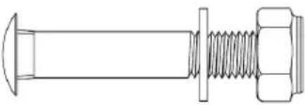 | 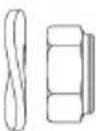 |
| #17 Bout M8*48#31 Plaatshouder ∅8.2*∅20*1.6#40 Nylon moer M8 | #26 Plaatsbewaarder ∅8.2*∅20*1.5R25 #40 Nylon Moer M8 |
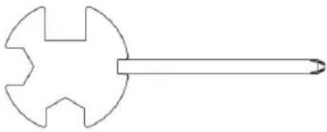 | 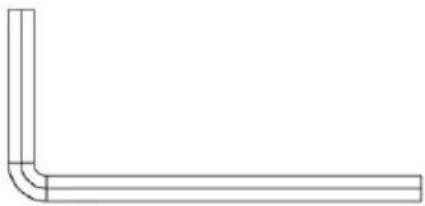 |
| Spanner Inbussleutel |
OPBOUW HANDLEIDING
text_image
Technical diagram of a mechanical device with numbered components and labeled partstext_image
Technical diagram of a mechanical assembly with numbered components and labeled partsnatural_image
Technical line drawing of a two- Ebats exercise bike with adjustable arm and seat (no text or labels)INSTRUCTIES VOOR AFVOER