I 400 - Heating Jøtul - Free user manual and instructions
Find the device manual for free I 400 Jøtul in PDF.
| Brand | Jøtul |
| Model | I 400 |
| Product type | Wood-burning fireplace |
| Material | Cast iron |
| Nominal heat output | 6 kW |
| Heat output range | 3.7 – 9 kW |
| Efficiency | 74 % |
| Weight | Approximately 110 to 125 kg |
| Fuel | Wood |
| Maximum log length | 40 cm |
| Connection diameter | 150 mm |
| Recommended draft | 12 Pa |
| Flue gas temperature | 259 °C |
| Flue gas mass flow | 7.3 g/s |
| CO emissions (at 13 % O2) | 0.19 % |
| HC emissions (at 13 % O2) | 86 mg/m3 |
| Operating mode | Intermittent |
| Available options | Ash drawer, outside air kit, grilles, flat smoke hood, decorative frame |
| Safety | Heat shield, required safety clearances |
| Maintenance | Replacement of baffles and lining plates |
| Cleaning | Regular chimney sweeping and ash removal |
Frequently Asked Questions - I 400 Jøtul
User questions about I 400 Jøtul
0 question about this device. Answer the ones you know or ask your own.
Ask a new question about this device
Download the instructions for your Heating in PDF format for free! Find your manual I 400 - Jøtul and take your electronic device back in hand. On this page are published all the documents necessary for the use of your device. I 400 by Jøtul.
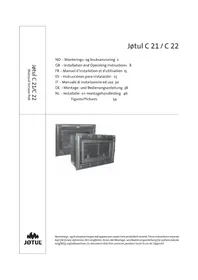
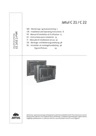
USER MANUAL I 400 Jøtul
Røykgass massestrøm:
Installation manual with technical data
1.0 Regulatory information 19
2.0 Technical data 19
3.0 Installation 20
4.0 Service 22
5.0 Optional Equipment 22
Figures 43
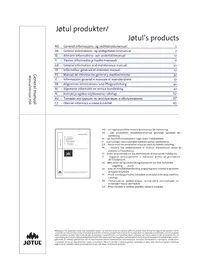
Table of contents
General use and maintenance manual
6.o Safety precautions
7.0 Choice of fuel
8.o Use
9.o Maintenance
10.o Operational problems - troubleshooting
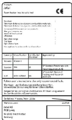
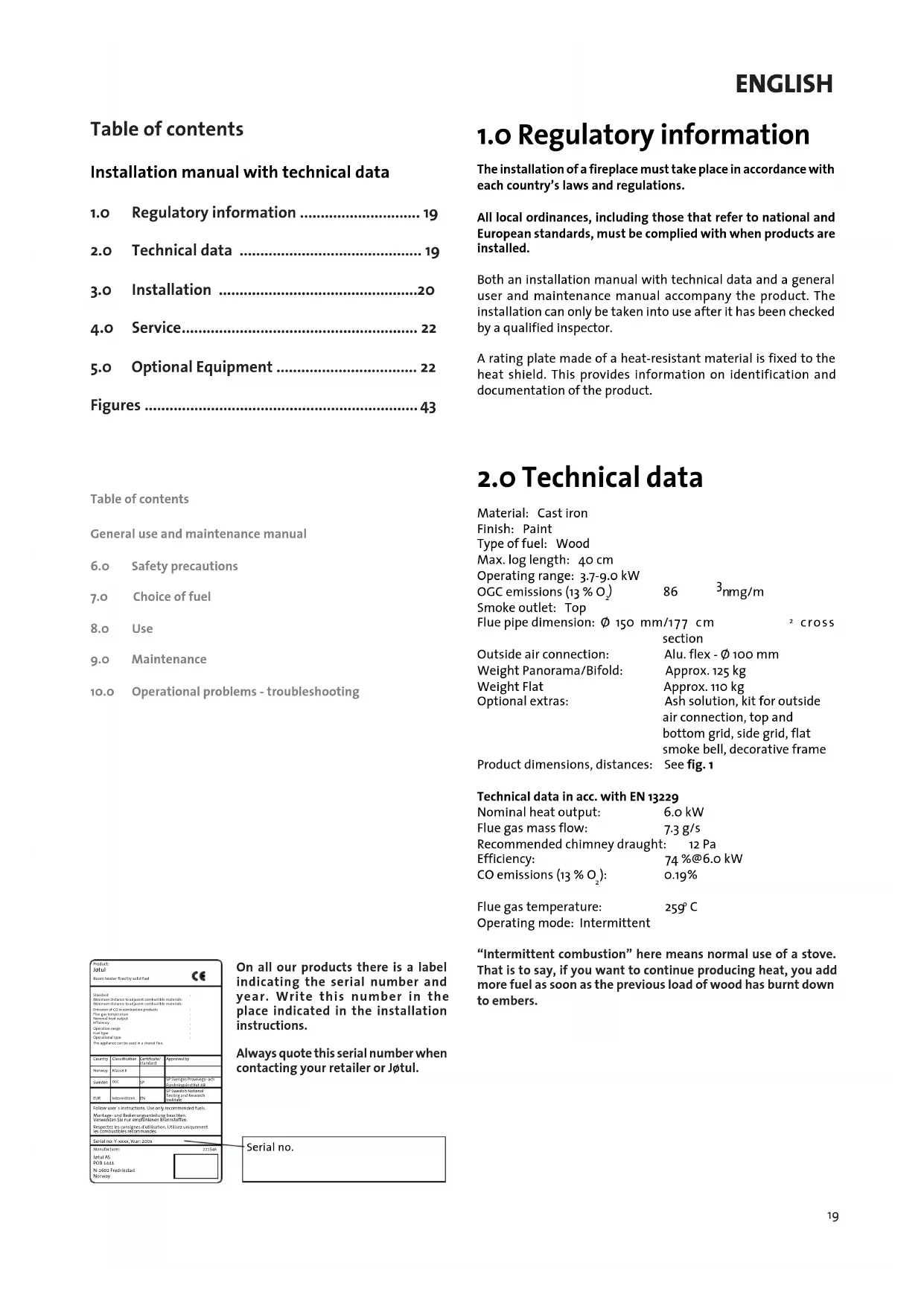
On all our products there is a label indicating the serial number and year. Write this number in the place indicated in the installation instructions.
Always quote this serial number when contacting your retailer or Jftul.
Serial no.
1.0 Regulatory information
The installation of a fireplace must take place in accordance with each country's laws and regulations.
All local ordinances, including those that refer to national and European standards, must be complied with when products are installed.
Both an installation manual with technical data and a general user and maintenance manual accompany the product. The installation can only be taken into use after it has been checked by a qualified inspector.
A rating plate made of a heat-resistant material is fixed to the heat shield. This provides information on identification and documentation of the product.
2.0 Technical data
Material: Cast iron
Finish: Paint
Type of fuel: Wood
Max. log length: 40 cm
Operating range: 3.7-9.0 kW
OGC emissions (13% O.)
Smoke outlet: Top
Flue pipe dimension: 150mm / 177cm
86
3nmg/m
section
Outside air connection:
Alu.flex-0100mm
Weight Panorama/Bifold:
Approx. 125kg
Weight Flat
Approx. 110 kg
Optional extras:
Ash solution, kit for outside
air connection, top and
bottom grid, side grid, flat
smoke bell, decorative frame
Product dimensions, distances: See fig. 1
Technical data in acc. with EN 13229
Nominal heat output:
6.0 kW
Flue gas mass flow:
7.3 g/s
Recommended chimney draught: 12 Pa
Efficiency:
74%@6.0 kW
CO emissions (13% O_2)
0.19%
Flue gas temperature: 25g C
Operating mode: Intermittent
"Intermittent combustion" here means normal use of a stove. That is to say, if you want to continue producing heat, you add more fuel as soon as the previous load of wood has burnt down to embers.
ENGLISH
Wood consumption
The efficiency of Jotull 400 gives it a nominal heat output of 6.0kW Wood consumption, at nominal heat output: Approx. 1.9kg / h The size of the pieces of wood should be:
Kindling (finely split wood):
Length: approx. 20-30 cm
Diameter: 2-5 cm
Quantity required each time: 6 - 8 pieces
Wood (split wood):
Recommended length: 30 cm
Diameter: Approx. 8 cm
Interval for adding wood: Approx. every 50 minutes
Fire size: 1.6kg (nominal output)
Quantity required each time: 3 pieces
Nominal heat output is achieved when the air vent is open approx. 40% (fig. 4A).
3.0 Installation
3.1 Floor
Foundations
You need to make sure the foundation is suitable for a stove. See "2.0 Technical data" for specified weight.
Requirements for protection of wooden flooring beneath the stove
Jotull 400 has a heat shield underneath to protect the floor from radiated heat. The product can therefore be positioned directly on a wooden floor that has been covered by a sheet of metal or other non-inflammable material. Recommended thickness minimum 0.9mm and must cover the entire floor surface within the surround.
It is recommended that flooring that is not attached to the actual floor surface – “floating floors” – be removed beneath the installation.
Any floor covering of inflammable material, such as linoleum, carpets, etc. must be removed from under the floor plate.
Requirements for protection of inflammable floors in front of the stove
The floor in front of the stove must be protected by a sheet of metal or other non-inflammable material. Recommended thickness is minimum 0.9 mm.
The front plate must comply with national laws and regulations.
Contact your local building authorities regarding restrictions and installation requirements.
3.2 Wall
Distance to inflammable wall protected by insulation (fig. 1)
Insulation requirements 50mm rock wool 120kg / m^3 with aluminium foil on one side.
Distance to inflammable wall protected by firewall (fig.1)
Requirements for regulation firewalls
The firewall must be a minimum of 100 mm thick and be made of brick, concrete or lightweight concrete. Other materials and structures with satisfactory documentation may also be used. Contact your local building authorities regarding restrictions and installation requirements.
Distance to non-inflammable wall (fig. 1)
"Non-inflammable wall" here means a non-bearing wall of continuous brickwork/concrete.
Requirements for fireplace surround
Fireplace surrounds must be made of a non-inflammable material.
Note that the entire back wall within the surround and other adjacent areas using inflammable materials must be covered with insulation/firewalls.
If the fireplace cowl is built up to the ceiling and the ceiling is of inflammable material, extra panelling must be installed above the top of the heating chamber and above the cowl's vents in order to prevent the ceiling becoming hot.
Use for example:
Rock wool 100 mm thick on a steel plate min. o.9 mm.
Ensure there is adequate ventilation at the top of the fireplace cowl - e.g. a gap towards the ceiling, or approx. 5cm^2 opening (fig. 2).
NBI Remember that it must be possible to sweep and inspect the installation.
3.3 Air supply (fig. 2)
Air must flow between the insert and the brickwork, and it is extremely important that there should be an unimpeded air supply to the air vents at both the top and bottom of the insert.
The air inlets specified in the text are minimum requirements. Necessary circulated air:
Base: Minimum 500 cm² free opening.
Top: Minimum 750 cm ^2 free opening.
This is to ensure that the build-up of heat inside the surround does not become too great and that heat output into the room is adequate.
If the building is poorly ventilated, the room should be furnished with an additional fresh air supply by means of vents, or a separate duct.
The fresh air duct should be as straight as possible. Ducts in the room where the stove is installed must be made of noninflammable material.
The product can be supplied with outside air (kit for outside air connection is available as an optional extra).
3.4 Ceiling
Jotul 400 can be fitted with the top edge of the hot air opening at least 350mm below a ceiling of inflammable material.
3.5 Chimney and flue pipe
- The stove can be connected to a chimney and flue pipe approved for solid fuel fireplaces with flue gas temperatures as specified in "2.0 Technical data".
- The cross section of the chimney must be at least that of the flue pipe. Use "2.o Technical data" to calculate the correct chimney cross section.
- Several solid fuel stoves can be connected to the same chimney system if the chimney cross section is adequate.
- Connection to the chimney must be performed in accordance with the installation instructions of the chimney supplier.
- Before a hole is made in the chimney, the stove should be moved into its provisional position to enable correct marking out of the position of the stove and hole in the chimney. See fig.1 for minimum dimensions.
- Make sure that the flue pipe rises all the way up to the chimney.
- Use a flue pipe bend with a sweep hatch to allow sweeping.
Please note that it is extremely important for connections to have a degree of flexibility. This is to prevent any movement in the installation leading to the formation of cracks.
NB! A correct and airtight connection is extremely important for the function of the product.
Weight must not be transferred from the fireplace structure to the chimney. The fireplace structure must not hinder the chimney's ability to move, and must not be anchored to the chimney.
For recommended chimney draught, see "2.o Technical data". If the draught is too strong, action must be taken, e.g. install and operate a flue pipe damper in order to reduce the draught.
3.6 Before installation
Check that the fireplace insert is undamaged before installation begins.
- The standard product comes in a single package.
- Once the product has been unpacked, take the box containing the smoke bell, log retainer., gasket and bag of screws out of the burn chamber. Then remove the air duct (fig. 4 D), baffle (fig. 5 B), exhaust deflector (fig. 5 A), side burn plates and rear burn plate (fig. 4 E).
Installation
The product is heavy! Make sure the product does not topple over.
Ensure you have help when positioning and installing it.
- Remove the heat shields by unscrewing the two screws, M8x20 mm, on either side (fig. 3 A) of the burn chamber.
- Lay the product carefully down on its back. You can put the cardboard packaging on the floor to protect it from scratches, etc.
- Remove the screws, M8x20 mm, holding the two side legs to the burn chamber. (fig. 6 A).
- Adjust the length of the side legs by fixing the bolt in the upper leg aperture as shown in the illustration (fig. 7A).
- Lay the product carefully over on its side and adjust the rear leg in the same way as for the side legs (fig. 8).
- Screw the foot screws (fig. 9 A) into the legs.
- Mount the heat shield (fig. 10 A) to the underside of the burn chamber using the accompanying screws and sleeves (fig. 10 B).
- Stand the product up carefully. Important! Adjust the foot screws slightly to level the product.
- Replace the exhaust deflector (fig. 5 A), baffle (fig. 5 B), side burn plates and rear burn plate (fig. 4 E), air duct (fig. 4 D) and log retainer (fig. 4 C).
- Replace the heat shield on the burn chamber using the same screws (fig. 18 A) they were fastened with before.
- Unscrew the upper heat shield at the rear (fig. 18 B). Turn it upside down and screw it firmly in position using the same screws it was fastened with before.
Installation of the smoke bell and flue pipe (fig. 12)
The smoke bell can be installed from outside or inside as required;
Option 1 - installed from outside (fig. 12 A):
- Install the accompanying gasket on the underside of the edge of the smoke bell in the gasket channel (fig. 12 A-2).
- Install the smoke bell from outside by fixing it in place using the four accompanying M8x20 mm screws (fig. 12 A-1).
- Then rotate the smoke bell to the desired position (fig. 17). Tighten the screws.
- Then install the flue pipe in the product's smoke bell. Use gasket rope between the smoke bell and the flue pipe.
ENGLISH
Option 2 - installed from inside (fig. 12 B):
- First screw in halfway and diagonally 2 screws with washers (fig. 13 A). Install the accompanying gasket on the top side of the edge of the smoke bell in the gasket channel (fig. 12 B-1).
- Move the smoke bell up inside the burn chamber so the smoke bell notch is against the screws with washers (fig. 14 A).
- Turn the smoke bell slightly so that it is resting on the screws with washers (fig. 15 A).
- Then screw in the two other screws (fig.16A) and then screw all the screws almost all the way in.
- Rotate the smoke bell to the desired position (fig. 17). Tighten the screws.
- Then install the flue pipe in the product's smoke bell. Use gasket rope between the smoke bell and the flue pipe.
3.7 Checking the functions (fig. 4)
Once the product has been assembled, always check the control handles. These must move easily, and work in a satisfactory manner.
Jøtul 1400 is equipped with the following operating options:
Air vent fig. 4 A
Left position closed
Right position fully open
Lighting vent fig. 4 B
Left position Closed
Right position Fully open
3.8 Ash removal
- Only remove ash when the stove is cold.
- Always leave some ash there as a protective layer over the bottom of the fireplace.
See also the description of how to handle ash in the General User and Maintenance Instructions under point "6.1 Fire Prevention Measures".
4.o Servicing
Warning!
Any unauthorised changes to the product are illegal!
Only original spare parts may be used!
4.1 Replacing the baffle/exhaust deflector (fig. 5)
NBI The burn plates are made of a porous material (yellow vermiculite) and may be damaged if they are handled roughly.
- Lift the baffle up on its side and ease it out (fig. 5 B).
- Lift the exhaust deflector (fig. 5 A) up slightly, pull it right back towards the rear wall and ease it out.
- To replace the baffle and exhaust deflector, follow the same procedure in reverse order.
4.2 Replacing the burn plates/air duct - (figs. 4 and 5)
NB! The burn plates are made of a porous material (yellow vermiculite) and may be damaged if they are handled roughly.
- Lift the baffle up on its side and ease it out (fig. 5 B).
- Remove the log retainer (fig. 4C).
- Then lift up the air duct (fig. 4D) and take it out.
- Take out the side burn plates (fig. 4 E) by tilting them out back edge first.
- Then remove the rear burn plate (fig. 4 E).
- To install them, follow the same procedure in reverse order.
5.o Optional extras
Ash solution - cat.no.51012161
Kit for outside
air connection - cat. no. 51012160
Top and bottom grid, straight, BP - cat. no. 51012157
Top and bottom grid, curved, BP - cat. no. 51043381
Side grid 65 mm, BP - cat. no. 51012158
Side grid 115 mm, BP - cat. no. 51012159
Low smoke bell - cat. no. 12019316
Decorative frame, BP - cat. no. 50043685
Sommaire
Massastroom rookgas:
7,3 g/sec.
Length: ongeveer 20-30 cm
Diameter: 2-5 cm
Stookopening fig. 4 B
Links
Rechts
Gesloten
Volledig
open
3.8 As verwijderen
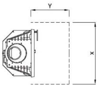
Min. mal forplate / front plate X / Y = Acc.to national standards and regulations.
Combustible wall Non combustible wall
* = Adjustble up 140mm
Mälene gjelder ubehandledeprodukter. Etter lakkering kan mälene variere noe.
Dimensions refer to untreated products. After dimensions may have small divergences.
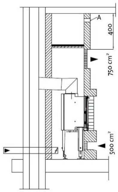
Fig. 2
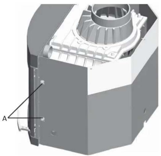
Fig. 3
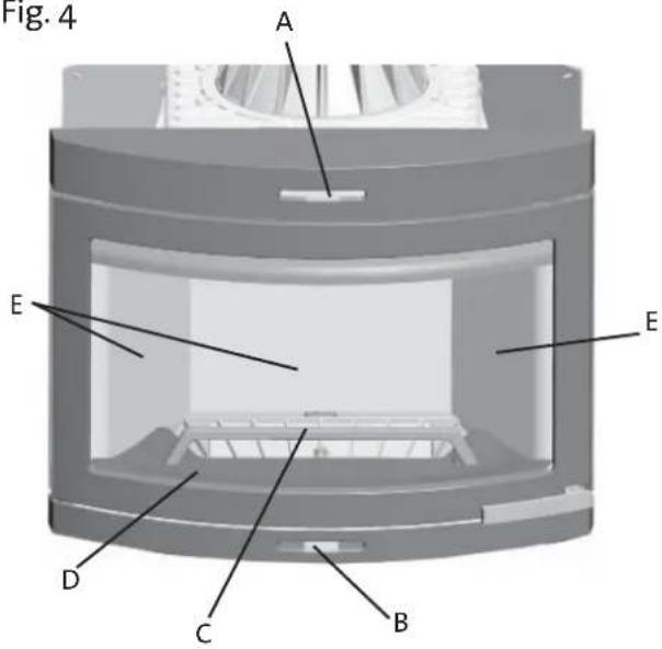
Fig. 4
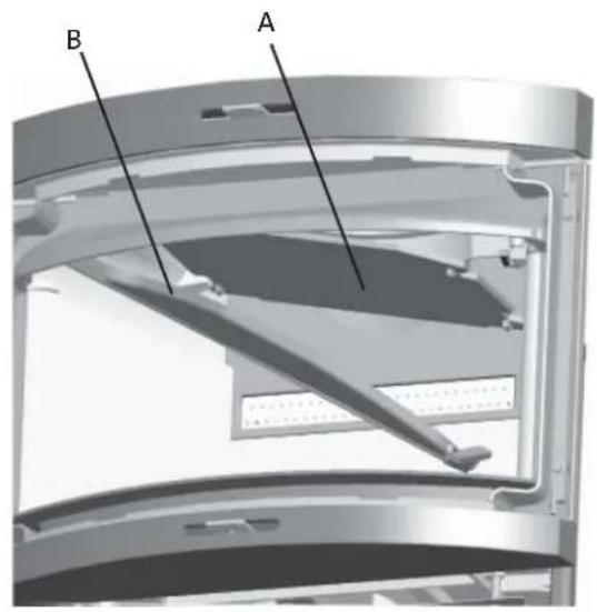
Fig. 5
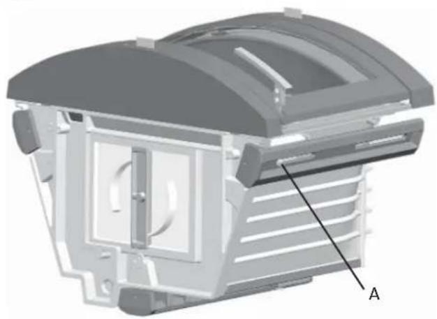
Fig. 6
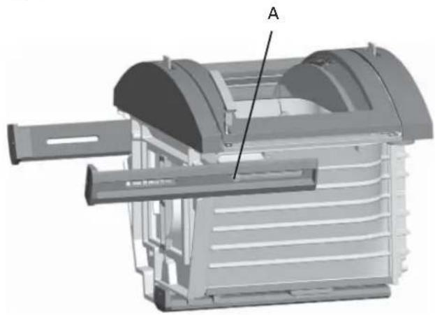
Fig. 7
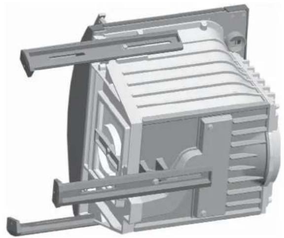
Fig.10
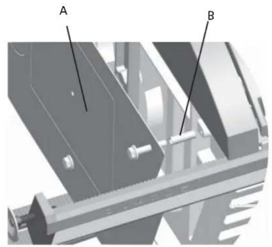
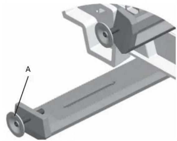
Fig.9Fig.8
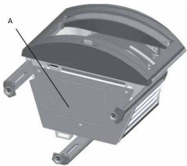
Fig. 11
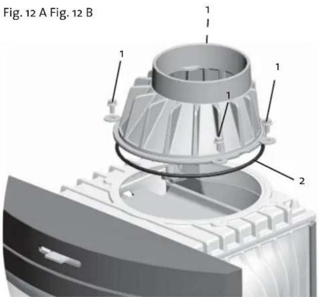
Fig. 12 A Fig. 12 B
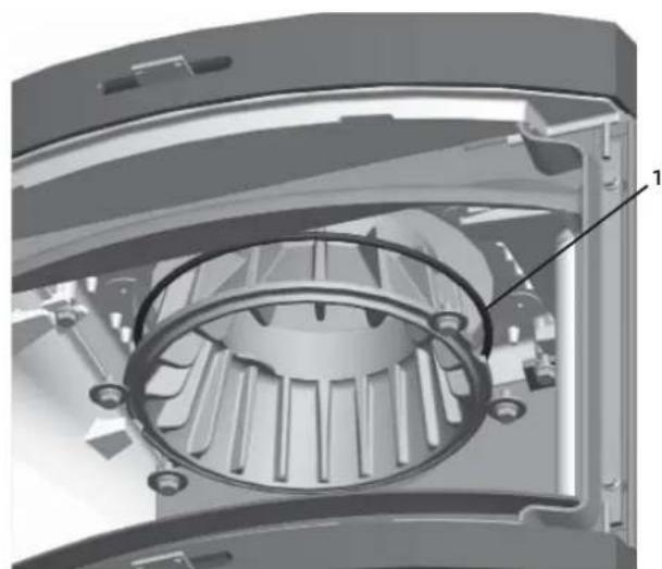
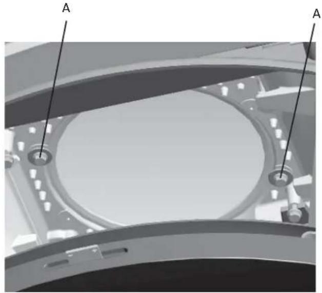
Fig. 13
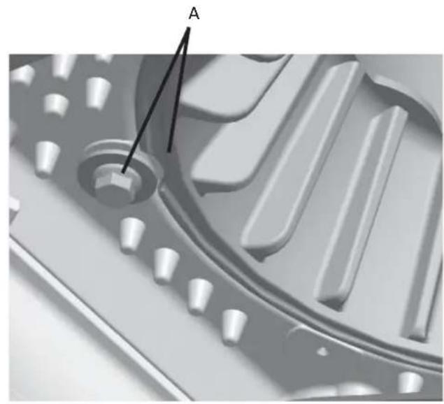
Fig.14
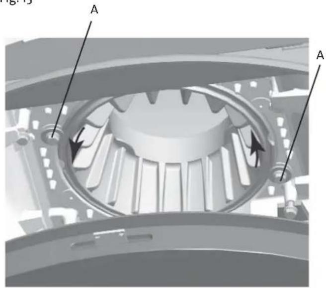
Fig. 15
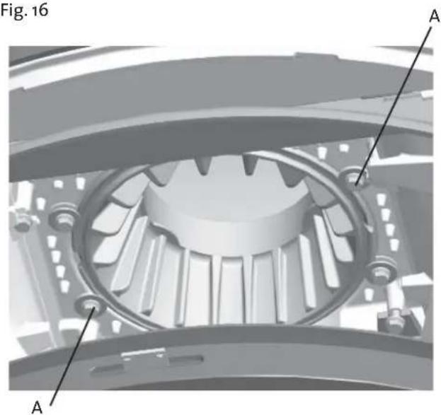
Fig. 16
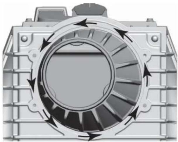
Fig.17
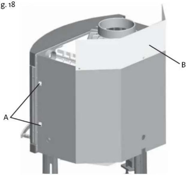
Fig.18
Quality control of stoves and fireplaces
Checked
Utfort Kontrollpunkt
Controlled item
Jøtul pursue a policy of constant product development. Products supplied may therefore differ in specification, colour and type of accessories from those illustrated and described in the brochure.
Jøtul AS has a quality system that conforms to NS-EN ISO 9001 for product development, manufacturing, and distribution of stoves and fireplaces. This policy gives our customers quality and safety piece of mind as a result of Jøtul's vast experience dating back to when the company first started in 1853.