F 118 - Heating Jøtul - Free user manual and instructions
Find the device manual for free F 118 Jøtul in PDF.
| Brand | Jøtul |
| Model | F 118 |
| Product type | Wood stove |
| Category | Heating |
| Material | Cast iron |
| Finish | Black paint |
| Fuel | Wood only |
| Nominal heat output | 7.0 kW |
| Efficiency | 73% |
| Recommended draft | 13 Pa |
| Flue gas mass flow | 8.4 g/s |
| Flue gas temperature | 301 °C |
| CO rate (at 13% O2) | 0.23% |
| Operating mode | Intermittent |
| Weight | ~145 kg |
| Maximum log length | 60 cm |
| Flue pipe diameter | 125 mm (150 mm adapter available) |
| Connection outlet | Top, side and rear |
| Available options | Side heat shield (cat. 320099) and rear heat shield (cat. 320098) |
| Maintenance | Regular ash cleaning, replacement of fire plates and baffle |
Frequently Asked Questions - F 118 Jøtul
User questions about F 118 Jøtul
0 question about this device. Answer the ones you know or ask your own.
Ask a new question about this device
Download the instructions for your Heating in PDF format for free! Find your manual F 118 - Jøtul and take your electronic device back in hand. On this page are published all the documents necessary for the use of your device. F 118 by Jøtul.
USER MANUAL F 118 Jøtul
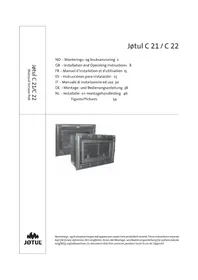
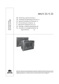
GB - Installation manual with technical data 11
Røykgass massestrøm:
8,4 g/s
Storlek pa brasan: 2,0 kg
Mängd per brasa: 2-3 stick.
3.5 Monteringfore installation
Viktigt! Kontrollera att eldstaden ar fri fr'an alla eventuella transportskador innan installationen paborjas.
Installation manual with technical data
1.0 Relationship to the authorities 11
2.o Technical data
3.o Installation
4.0 Service
5.o Optional Equipment
6.o Information 14
Figures/Pictures 35
General use and maintenance manual
6.o Safety precautions
7.0 Choice of fuel
8.o Use
9.o Maintenance
10.o Operational problems - troubleshooting
1.0 Relationship to the authorities
Installation of a fireplace must be according to local codes and regulations in each country. All local regulations, including those that refer to national and European standards, shall be complied with when installing the product.
12 Instructions for mounting, installation and use are enclosed with the product. Prior to using the product the installation must be approved by a qualified person.
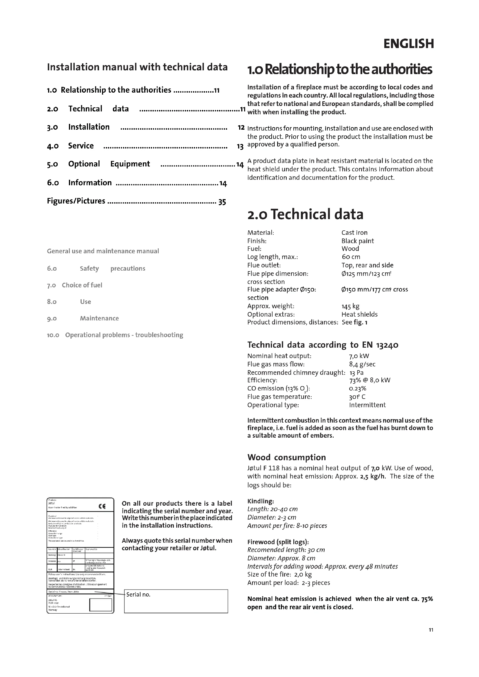
A product data plate in heat resistant material is located on the heat shield under the product. This contains information about identification and documentation for the product.
2.0 Technical data
Material: Cast iron
Finish: Black paint
Fuel: Wood
Log length, max.: 60 cm
Flue outlet: Top, rear and side
Flue pipe dimension: 125mm / 123cm^2
cross section
Flue pipe adapter 150 .. 0150mm / 177cm cross section
Approx. weight: 145 kg
Optional extras: Heat shields
Product dimensions, distances: See fig. 1
Technical data according to EN 13240
Nominal heat output: 7,o kW
Flue gas mass flow: 8,4 g/sec
Recommended chimney draught: 13 Pa
Efficiency: 73% @ 8,o kW
CO emission (13%) .. 0.23%
Flue gas temperature: 30°C
Operational type: Intermittent
Intermittent combustion in this context means normal use of the fireplace, i.e. fuel is added as soon as the fuel has burnt down to a suitable amount of embers.
Wood consumption
Jotul F 118 has a nominal heat output of 7,0 kW. Use of wood, with nominal heat emission: Approx. 2,5 kg/h. The size of the logs should be:
Kindling:
Length: 20-40 cm
Diameter: 2-3 cm
Amount per fire: 8-10 pieces
Firewood (split logs):
Recommended length: 30~cm
Diameter: Approx. 8 cm
Intervals for adding wood: Approx. every 48 minutes
Size of the fire: 2,0 kg
Amount per load: 2-3 pieces
Nominal heat emission is achieved when the air vent ca. 75% open and the rear air vent is closed.
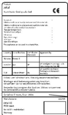
On all our products there is a label indicating the serial number and year. Write this number in the place indicated in the installation instructions.
Always quote this serial number when contacting your retailer or Jotul.
Serial no.
ENGLISH
3.0 Installation
3.1 Floor
Foundations
It must be ensured that the foundations are dimensioned for the fireplace. Cf. «2.0 Technical data» for specification of weight. It is recommended that flooring which is not fastened to the foundations - so-called floating flooring - is removed during installation.
Wooden floor protection
Requirements for the floor plate:
If the product is placed directly on a wooden floor, the floor must be covered by a metal plate or other suitable, non-inflammable material. The recommended minimum thickness is 0,9mm . Any flooring made of combustible material, such as linoleum, carpets, etc. must be removed from under the floor plate.
Requirement for protecting combustible flooring in front of fireplace
The front plate must be in accordance with national laws and regulations. Contact your local building authorities regarding restrictions and installation requirements. (See Buildings Regulations.)
3.2 Walls
Distance to walls made of combustible material-see fig.1. The fireplace is authorised for use with an uninsulated flue with the distances to the wall of flammable material as shown in fig 1.
Distance to walls protected by a firewall - see fig.1
Firewall requirement
The firewall must be at least 100mm thick and be made of brick, concrete-stone or light concrete. Other materials and constructions with satisfactory documentation may also be used.
Distance to non combustible wall
A non combustible wall is here mentioned as a non load-bearing wall of cement /brick.
Recommended distance: 100 mm.
3.3 Ceiling
There must be a minimum distance of 1200 mm to a combustible roof above the fireplace.
3.4 Chimneys and flue pipes
- The fireplace can be connected to a chimney and flue pipe approved for solid fuel fired fireplaces with flue gas temperatures specified in «2.0 Technical data».
- The chimney's cross-section must be at least as big as the flue pipe's cross-section. See «2.0 Technical data» when calculating the correct chimney cross-section.
Several solid fuel fired fireplaces can be connected to the same chimney if the chimney's cross-section is sufficient.
- Connection to the chimney must be carried out in accordance with the installation instructions from the supplier of the chimney.
- Before making a hole in the chimney the fireplace should be test-mounted in order to correctly mark the position of the fireplace and the hole in the chimney. See fig.1 for minimum dimensions.
- Ensure that the flue pipe is inclined all the way up to the chimney.
- Use a flue pipe bend with a sweeping hatch that allows it to be swept.
Be aware of the fact that connections must have a certain flexibility in order to prevent movement in the installation leading to cracks. N.B. A correct and sealed connection is very important for the proper functioning of the product.
The chimney draught, see «2.o Technical data». If the draught is too strong you can install and operate a flue damper to control the draught.
3.5 Assembly prior to installation
N.B. Check that the fireplace is free of any damage prior to commencing installation. The product is heavy! Make sure you have assistance when erecting and installing the fireplace.
The product is delivered in a single packing case where the legs, heat shield(s) and door knob/vent knobs must be assembled.
A heat shield for the floor shall always be used. A heat shield for the side or back can be ordered and mounted depending on the position of the fireplace and the desired distance to combustible materials. See fig. 1.
When the product has been unpacked remove all loose parts from the fireplace. Check the product for any physical damage.
- Unfold the cardboard packing and place the wooden pallet on top. Carefully place the fireplace on its side. Mount the four legs using screws and washers. (Fig. 2)
- The floor shall be protected from heat from the product using the supplied heat shield.
Mounting the heat shield under the stove, see fig. 3
- Fasten the heat shield under the middle using 2M6 × 12 screws (see fig 3)
- Carefully stand the fireplace on its legs.
Mounting the heat shield on the side (optional equipment), see fig. 4
- Feed the upper clamps in under the top plate.
- Loosen the 2M6 × 12 screws that are screwed into the bottom of the fireplace (A), and use them to attach the heat shield.
Mounting the heat shield on the back (optional equipment), see fig. 5
In order to be able to place the fireplace's rear wall closer to a wall made from combustible material (see fig. 1) a heat shield can be mounted on the product.
- Remove the screws in the middle of the back-plate and throw them away, see fig.
- Mount the heat shield using the screws and sleeves included.
Loosen the hotplate, attached from underneath using a crossbar, and allow it to rest loosely on the fireplace in order to make subsequent cleaning easier.
- In order to remove the hotplate the top plate must be removed.
- Loosen the screw (if fitted) that holds the rear heat shield and remove the heat shield (fig. 5)
- Remove the top plate by unscrewing 2 screws at the back of the fireplace.(fig. 6) (Use the _3 mm Allen key in the screw bag). Tilt the plate up at the back and lift it up and remove it.
- Remove the crossbar holding the hotplate. (fig. 7).
Attaching the smoke outlet
- Choose which smoke outlet you wish to use and if necessary switch the position from the rear to the side/top and seal the other opening with the cover.
- Mount the smoke outlet with a gasket and 2 M6 x 16 screws.
- Mount the 125mm flue pipe on the outside of the smoke outlet. Use a gasket to obtain a sealed joint. It is also possible to use the flue pipe adapter when mounting 150 pipe internally.
- Attach the top plate by feeding the washer in the front edge under the rib and fasten it with the Allen screws in the rear edge. (See fig. 8 and 6)
- Place the hotplate in position.
- Mount the wooden knob on the door handle and the plastic knob on the vent lever. The parts are in the bag that is included. (fig. 8)
3.6 Control functions (fig. 9)
Check that there is no visible damage to the product when you unpack it, and make sure that the control handles move freely.
Jotul F 118 is equipped with the following controls:
Air vent, fig. 9A
To the left: Closed
To the right: Open
Ignition vent, fig. 9B
Pushed all the way in: Closed
Pulled out: Open
3.7 Ash removal
- Use a scoop or similar to remove the ash through the door.
Always leave some ash as a protective layer on the bottom of the fireplace. - Ash must be placed in a metal container with a sealed lid. For the rest, see description of how to handle ash in the Manual on general use and maintenance in Point «6.1 Fire preventive measures».
4.o Service
Warning! Any unauthorised change to the product is illegal.
Only use original spare parts!
4.1 Replacing the baffle (fig. 11 - 14)
- Loosen the screw (if fitted) that holds the rear heat shield and remove the heat shield (fig. 5A)
- Unscrew the two nuts at the back of the fireplace that hold the long secondary air pipes (fig. 11A).
- Use a screwdriver to push out the clamps holding the baffle (fig. 12).
- First pull one of the long pipes out of the slot (fig. 13) and towards the middle and a little downwards.
- Remove the middle secondary air pipe that rests on the long pipes. (fig. 14)
- Also pull the other long pipe towards the middle and pull both out through the door.
- Lift the baffle up a little and tilt it downwards and out of the door. The insulation mat that rests on the baffle will then come with the baffle.
For reassembly follow the same procedure for installation, but in reverse.
Place the insulation mate (fig. 16) in position through the hole for the hotplate. (Ensure that the front edge of the insulation mat is in line with the front of the baffle and is up to the back plate at the rear edge.
- Tighten the screws at the back a little before placing the middle pipe in position. Remember that the cut-out (for the middle pipe) in the long pipes shall point upwards.
- The middle pipe has a larger hole (see fig. 14A) that shall point upwards and fit into the tabs on the baffle. The secondary air holes shall face forwards.
- Tighten the screws at the back.
4.2 Replacing the side burn plates, fig. 15
Lift the burn plate up a little (fig. 15B) using the handle in the middle - (see fig. 15A) and tilt it out through the door.
If it becomes stuck use a screwdriver and prisit up from the lower edge.
For reassembly follow the same procedure for installation, but in reverse.
N.B. Remember to clean the base where the burn plate is placed so that it can be positioned correctly.
4.3 Replacing stones in the back wall, fig. 15
- Lift the stone holder and the upper stone (fig.15B-C) together and tilt them out of the slot at the back.
- Then lift up the lowest stone.
For reassembly follow the same procedure for installation, but in reverse.
ENGLISH
5.0 Optional Equipment
Heat shield on the side, fig. 4 cat. nr. 320099.
Heat shield on the back, fig. 5 cat. nr. 320098.
6.o Information
Text written on Jøtul F 118 front plate, free translated from
Norwegian (Fig. 17).
I built me a flame
late at night
When day is done
God will my flame
never dies out>.
Text written on Jotul F 118 front plate translated from Norwegian (afb. 17)
I built me a flame.
late at night
When day is done
God will my flame
never dies out.
Produkt Product
Min. māl gulpvate / min measure flourplate X / Y = Acc.to rational standards and regulations
Min. avstand til brennbar veg Min. distance to combustible wall
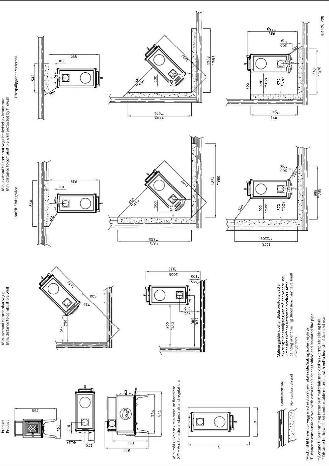
Min. avstand til brennbar vegb beskyttet ab brannmur Min. distance to combustible wall protected by firewall
Utenpåliggende/external
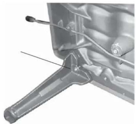
Fig. 2
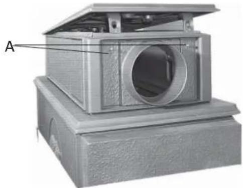
Fig.6
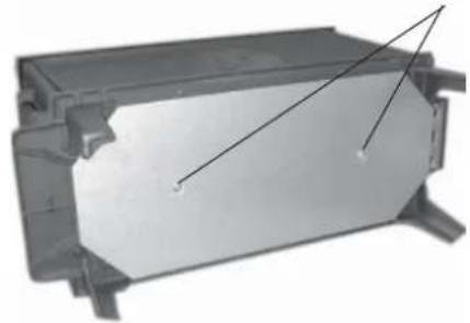
Fig. 3
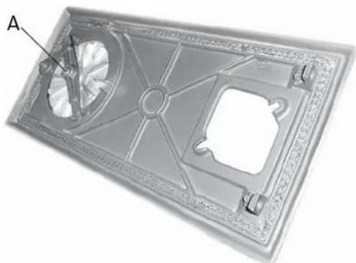
Fig.7
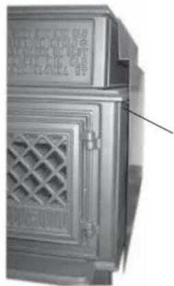
Fig.4
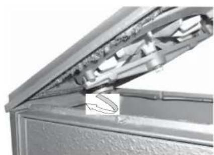
Fig. 8
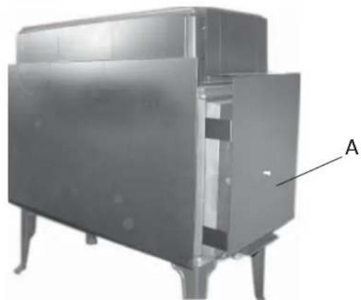
Fig. 5
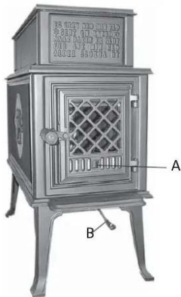
Fig. 9
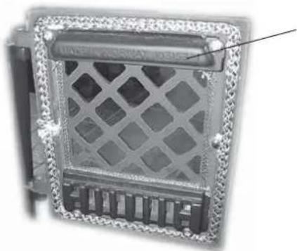
Fig. 10
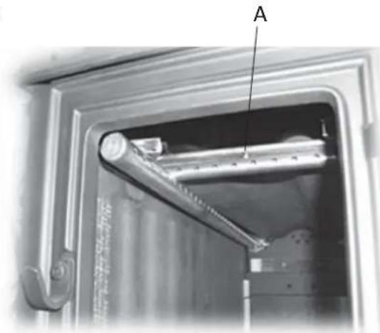
Fig. 14
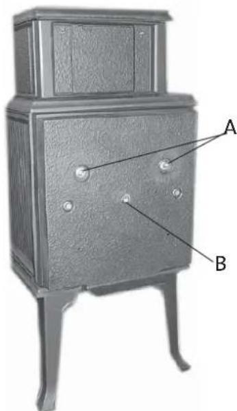
Fig. 11
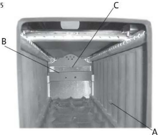
Fig. 15
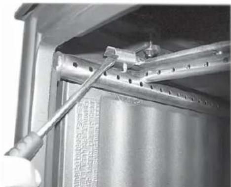
Fig. 12
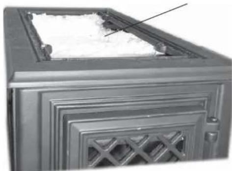
Fig. 16
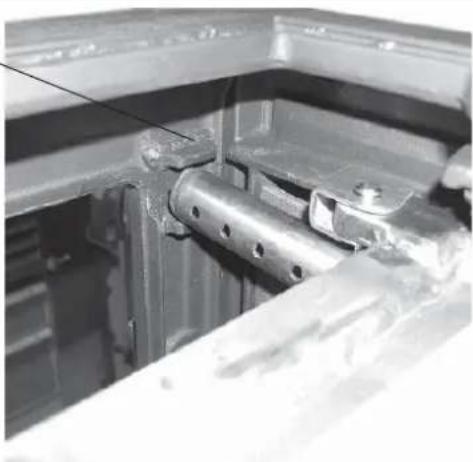
Fig. 13
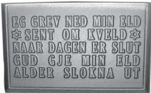
Fig. 17
Quality control of stoves and fireplaces
Checked
Utfort Kontrollpunkt
Controlled item
Jotul pursue a policy of constant product development. Products supplied may therefore differ in specification, colour and type of accessories from those illustrated and described in the brochure.
Jøtul AS has a quality system that conforms to NS-EN ISO 9001 for product development, manufacturing, and distribution of stoves and fireplaces. This policy gives our customers quality and safety piece of mind as a result of Jøtul's vast experience dating back to when the company first started in 1853.