CCTVSET10 - Surveillance Camera Perel - Free user manual and instructions
Find the device manual for free CCTVSET10 Perel in PDF.
| Type of product | Surveillance camera set with digital recorder |
| Brand | Perel |
| Model | CCTVSET10 |
| Recorder dimensions | 200 x 210 x 130 mm |
| Recorder weight | 2250 g |
| Camera dimensions | ∅ 45 x 55 mm |
| Camera weight | 290 g (each) |
| Recorder power supply | 12 VDC via included power adapter (100-240 VAC) |
| Camera power supply | 12 VDC / 300 mA (included in cable) |
| Main functions | H.264 recording, motion detection, IR night vision, network connection (LAN/Internet), PTZ control, USB backup, OSD menu |
| Recording type | Manual, scheduled, motion detection, continuous |
| Hard drive capacity | 500 GB internal SATA (pre-installed) |
| Recording resolution | D1, HD1, CIF (PAL) |
| Number of cameras | 4 color CMOS cameras with IR |
| Night vision | Black and white with 11 IR LEDs |
| Care and cleaning | Unplug before cleaning; use a dry, lint-free cloth |
| Safety | Indoor use only; protect from moisture, splashes and excessive heat; do not open the housing (risk of electric shock) |
| Spare parts and repairability | Replaceable SATA hard drive (see manual); replaceable remote control batteries (LR03); no other spare parts specified |
| General information | Velleman warranty; privacy protection; operating temperature: 10°C ~ 40°C |
Frequently Asked Questions - CCTVSET10 Perel
User questions about CCTVSET10 Perel
0 question about this device. Answer the ones you know or ask your own.
Ask a new question about this device
Download the instructions for your Surveillance Camera in PDF format for free! Find your manual CCTVSET10 - Perel and take your electronic device back in hand. On this page are published all the documents necessary for the use of your device. CCTVSET10 by Perel.
USER MANUAL CCTVSET10 Perel
CONSUMER 7" LCD SECURITY SET: DVR + 4 CAMERAS + ACCESSORIES + 500GB HARD DISK
7" LCD BEVEI LIGINGSPACK: DVR + 4 CAMERA'S + 500GB HARDDISK + ACCESSOI RES
PACK VIDÉOSURVEILLANCE 7" LCD : ENREGISTREUR NUMÉRIQUE + 4 CAMÉRAS + DI SQUE DUR 500Go + ACCESSOI RES
JUEGO DE VIGILANCI A 7" LCD: VIDEOGRABADORA DIGITAL + 4 CÁMARAS + DISCO DURO 500GB + ACCESORIOS
natural_image
Black-and-white photo of a surveillance camera with multiple security cameras mounted on a display screen (no visible text or symbols)USER MANUAL 3
GEBRUIKERSHANDLEIDING
NOTICE D'EMPLOI 53
MANUAL DEL USUARIO 78
BEDIENUNGSANLEITUNG
MANUAL DEL USUARIO 128
28
103
CE
text_image
2018-03-05 22:35:28 CH1 CH2 CH3 CH4 5 6 7 8 9 10 POWER REC ALM HDD NET 1 LCD ON/OFF 2 Standby 3 MENU EXIT 4 OK 11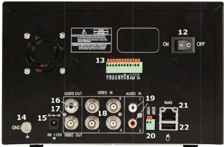
text_image
12 ON OFF 13 AUDIO OUT VIDEO IN AUDIO IN 19 DJ45A 485A 485B 21 GND 16 17 18 1 20 DC +12V IN VIDEO OUT RJ45 22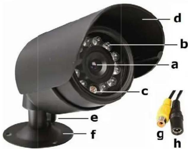
text_image
d b a c e f g h
text_image
A STANDBY B LOGINLOCK 1 2 3 C 4 5 6 7 8 9 D E F PTZ G H OK + - I J K L RECORD STOP EXTRA M AUDIO MLTEUser manual
1. Introduction
To all residents of the European Union
Important environmental information about this product

This symbol on the device or the package indicates that disposal of the device after its lifecycle could harm the environment. Do not dispose of the unit (or batteries) as unsorted municipal waste; it should be taken to a specialized company for recycling. This device should be returned to your distributor or to a local recycling service. Respect the local environmental rules.
If in doubt, contact your local waste disposal authorities.
Thank you for choosing Perel! Please read the manual thoroughly before bringing this device into service. If the device was damaged in transit, do not install or use it and contact your dealer. Damage caused by disregard of certain guidelines in this manual is not covered by the warranty and the dealer will not accept responsibility for any ensuing defects or problems.
Package content:
- 1 x D VR with built-in SATA hard disk
- 4 x IR colour CMOS cameras
- 4 x 18 m camera cables (video + power)
- 1x power adaptor 100\~240VAC/50\~60Hz to 12VDC (5x) + power cable
- IR re mote control + AAA batteries
- USB mouse
- 1x CD -ROM containing the full user manual
2. Safety Instructions

Keep the device away from children and unauthorised users.

Risk of electroshock when opening the cover. Touching live wires can cause life-threatening electroshocks.

Always disconnect mains power when the device is not in use or when servicing or maintenance activities are performed. Handle the power cord by the plug only.
3. General Guidelines
Refer to the Velleman® Service and Quality Warranty on the last pages of this manual.

Indoor use only. Keep this device away form rain, moisture, splashing and dripping liquids. Never put objects filled with liquid on top.
Keep this device away from dust and extreme temperatures. Make sure the ventilation openings are clear at all times. For sufficient air circulation, leave at least 1" (±2.5 cm) in front of the openings.

Protect this device from shocks and abuse. Avoid brute force when operating the device.
- Familiarise yourself with the functions of the device before actually using it.
- All modifications of the device are forbidden for safety reasons.
- Only use the device for its intended purpose. Using the device in an unauthorised way will void the warranty.
- Damage caused by disregard of certain guidelines in this manual is not covered by the warranty and the dealer will not accept responsibility for any ensuing defects or problems.
- Do not use this product to violate privacy laws or perform other illegal activities.
4. Features
DVR
• H.264 recording
• recording via motion trigger, manual and timer
- backup function: USB/LAN
- OSD menu: English, Chinese
- user manual: English, French, German, Spanish and Dutch
• SATA Hard disk (500Gb) built-in
• system auto recovery after power reconnected
• DVR Control: DVR buttons, IR remote control and USB mouse
Camera (4x)
• CMOS colour camera
• with B/W night vision (IR LEDs)
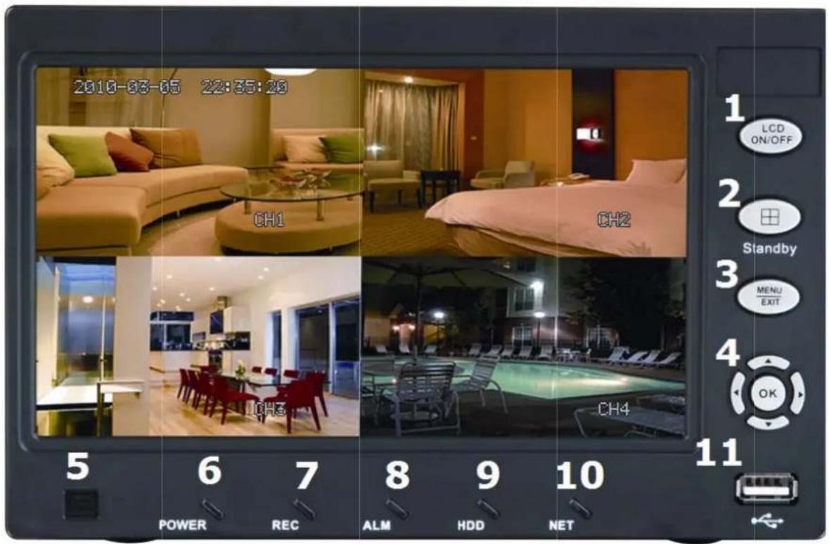
5. Overview
Refer to the illustrations on page 2 of this manual.
Front panel
| 1 | LCD ON /OFF switch | 7 | recording LED |
| 2 | channel selector / quadruple view | 8 | alarm LED |
| 3 | menu/e xit button | 9 | HDD LED |
| 4 | arrow b uttons + confirmation button (OK) | 10 | network LED |
| 5 | IR recei ver | 11 | USB port |
| 6 | power LED | ||
Rear panel
| 12 power ON/OFF switch | 18 | video input channel 1~4 (BNC) |
| 13 alarm signal connector | 19 | audio input I/R |
| 14 ground terminal | 20 | PTZ/RS-485 connector |
| 15 12 VDC input | 21 | network connector |
| 16 audio out | 22 | USB mouse port |
| 17 video out | ||
Camera
| a lens | e | position bolt |
| b IR LEDs | f | mounting bracket |
| c light se rsor | g | Video output connector |
| d sunshiel d | h | DC 12V input terminal |
Remote control
| A | STAND BY | turn standby mode on or off |
| B | LOGIN/ LOCK | open password login screen (when security is enabled) |
| C | num. ke ys | press to display corresponding channel in full screen (5~9 not applicable) or press to enter values during setup |
| D | press to select channel or quadruple view | |
| E | MENU | open main menu |
| F | PTZ | open PTZ control window (not applicable) |
| G | EXIT | go to previous menu / exit main menu |
| H | navigati on | to navigate, OK to confirm |
| I | + / - | increase / decrease value |
| J | RECOR D | start manual recording |
| K | STOP | stop manual recording |
| L | EXTRA | not used |
| M | playbac k controls | |
| ◀ | reverse playback speed 2x, 4x, 8x | |
| ▶ | start playback | |
| ▶▶ | increase forward playback speed 2x, 4x 8x | |
| ▶▶▶ | decrease forward playback speed 1/2x, 1/4x 1/8x | |
| ■▶▶ | press to freeze, press again to see next frame | |
Note: other keys on the remote control have no function programmed for this DyR.
6. Hardware setup
Refer to the illustrations on page 2 of this manual.
- The DVR comes with a HDD installed. To replace it, refer to §11)
- Make sure the device is unplugged from the mains before making any connections and do not touch any electronic circuitry to avoid electrostatic discharge.
Connecting the cameras
- Choose a location for the camera, keeping following guidelines in mind:
- do not install the camera in locations where extremely high or low temperatures or excessive vibrations may occur.
- avoid mounting the camera near high electro-magnetic fields.
- do not aim the camera at the sun or other extremely bright objects or reflections (e.g. metal doors).
- The included signal/power cables are 18m each.
- Use the mounting bracket [f] to determine the location of the mounting holes. Drill the holes and secure the bracket [f] using 3 screws.
- Attach the camera to the mounting bracket [f] with the camera bolt (rear).
- Point the camera towards the field of interest and tighten the position bolt [e].
- Connect the power [h] and RCA [g] connector to the signal/power cable.
- Connect the other end of the signal/power cable to the DVR. The channel number is indicated above the BNC connector [18]. It determines the position of the image on the screen.
- Connect the power connector to one of the 5 adaptor outputs.
Connecting the mouse
- Plug the USB-mouse connector into the USB input [22] at the rear of the DVR.
Connecting external alarms / RS485
- When desired, connect external alarm inputs (e.g. from door/window contacts) to the alarm input connector [13].
Connecting ground
- Connecting the ground terminal [14] to earth might resolve any image interference problems. Do not connect when the image is fine.
Connecting the power supply
- Plug a DC output connector of the included power adaptor into the 12VDC power input [15] at the back of the DVR.
WARNING: only use the included adaptor.
- Plug the included power cable into the adaptor input connector and plug the other end into the mains.
- Switch to DVR on with the ON/OFF switch [12].
Connecting Local Area Network (LAN)
- Connect the DVR to a local network by plugging a network cable into the LAN port [21] at the back of the DVR. Connector type is 8P8C (RJ45). Setup is done through the OSD.
7. Operation
Note: the functions, navigation and options of the DVR are accessible via the front panel, the remote control or by using the mouse.
- Switching on the DVR with the ON/OFF switch [12] at the back. It takes about 45 seconds for the initialization to complete and to show live images.
- After start-up, the power LED [6] is on and the display shows the 4 camera channels simultaneously. Date and time is shown in the top area of the display. Should one of the images remain blank, check the camera and cabling of that channel.
- Press the LCD power switch [2] to switch the LCD screen on or off. This does not interrupt the recording operation of the DVR!
Standby Mode
The system can also be put into standby mode. Power will remain to the system but recording is disabled. To start/stop Standby mode:
- Press and hold the STANDBY button on the front panel [2] or remote control [A] until the progress bar filled up completely. The system enters standby mode.
- Press and hold the STANDBY button on the front panel [2] or remote control [A] for ±3 seconds. The system will power up again.
Password
ATTENTION: By default, passwords are disabled on the system. You do not need to enter a password when accessing any system menu. However, for security purposes, it is highly recommended to enable passwords on the system using the password menu. Refer to §7.3.4.
NOTE:
- If there is no HDD in device, or the device can't read the HDD, or the HDD isn't formatted, a [H] is displayed in the video preview interface.
- The HDD in the DVR must be formatted before first use. Refer to §7.3.3.
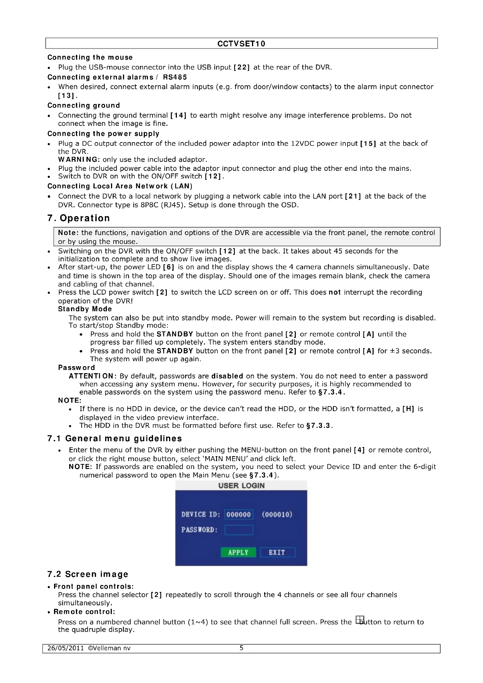
7.1 General menu guidelines
- Enter the menu of the DVR by either pushing the MENU-button on the front panel [4] or remote control, or click the right mouse button, select 'MAIN MENU' and click left.
NOTE: If passwords are enabled on the system, you need to select your Device ID and enter the 6-digit numerical password to open the Main Menu (see §7.3.4).

text_image
USER LOGIN DEVICE ID: 000000 (000010) PASSWORD: APPLY EXIT7.2 Screen image
- Front panel controls:
Press the channel selector [2] repeatedly to scroll through the 4 channels or see all four channels simultaneously.
- Remote control:
Press on a numbered channel button (1\~4) to see that channel full screen. Press the button to return to the quadruple display.
CCTVSET10
- Mouse control:
Left-click 2x on any channel to display that channel full screen. Double-click again to return to quadruple view.
7.3 Menu options
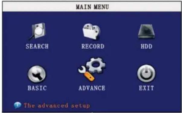
- Following menu options are available:
Search - Record - HDD - Basic - Advance - Exit
text_image
MAIN MENU SEARCH RECORD HDD BASIC ADVANCE EXIT The advanced setup
7.3.1 SEARCH
text_image
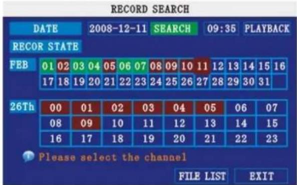
RECORD SEARCH DATE 2008-12-11 SEARCH 09:35 PLAYBACK RECOR STATE FEB 01 02 03 04 05 06 07 08 09 10 11 12 13 14 15 16 17 18 19 20 21 22 23 24 25 26 27 28 29 30 31 26Th 00 01 02 03 04 05 06 07 08 09 10 11 12 13 14 15 16 17 18 19 20 21 22 23 Please select the channel FILE LIST EXITNOTE: When you first open the Search menu, it will display the current month and date.
To perform a Quick Search:
Open the Search menu and click PLAY. The last minute of recorded playback begins.
To perform a Date & Time search:
1) Under DATE, click the field and enter the desired date using the virtual Keyboard and then click SEARCH. The system searches for data.
2) Under RECORD STATE, the system shows recorded events in a month grid and a time Grid. The selected day of the month will be outlined in red. Green=normal recording; Red=alarm recording (including both alarm and motion events).
3) Click a date in the month grid to view recorded video files for that selected date in the hour grid.
4) During playback, use the onscreen controls or the playback buttons on the remote control or front panel to control playback.
FILE LIST
Use the File List sub-menu to see a detailed list of all the recorded video on your system.
To open the File List:
1) From the Search Menu, click SEARCH to search the system for recorded video.
2) Click FILE LIST at the bottom of the menu. The File List menu opens.
FILE LIST
text_image
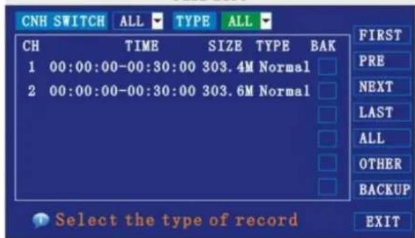
CNH SWITCH ALL TYPE ALL CH TIME SIZE TYPE BAK 1 00:00:00-00:30:00 303.4M Normal 2 00:00:00-00:30:00 303.6M Normal FIRST PRE NEXT LAST ALL OTHER BACKUP EXIT Select the type of recordTo use the File List:
1) Under CHN SWITCH, select individual channels or select ALL.
2) Under TYPE, select NORMAL to view only normal recordings, ALARM, to view alarm recordings (includes alarm and motion detection), or ALL to view all video on your system.
3) Use the buttons on the side panel to navigate the file list:
• FIRST: Jump to the first page of the list
• PRE: Turn to the previous page
- NEXT: Turn to the next page
• LAST: Jump to the last page of the list
- ALL: Select all files
- OTHER: Clear all files
- BACKUP: After selecting a file(s), click to begin copying the data to a USB flash drive (not included);
4) Click any file to begin playback.
BACKUP
NOTE: The system is compatible with most major brands of USB flash drives, with capacities from 256 MB to 4 GB.
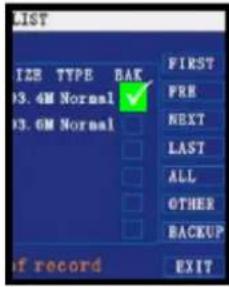
To backup recorded data:
1) Connect a blank USB flash drive to the bottom USB port on the front panel of the system.
2) Open the Search menu and search for recorded data on the system, click FILE LIST and select the files you want to backup.
3) Click the "BAK" box next to the filename. Select multiple files if desired, click ALL to select all files; click OTHER to deselect all files.
NOTE: The size of each file is shown in the File List menu. Use this to help you find a USB flash drive large enough to hold all the files you wish to backup.
4) Click BACKUP from the side-panel to immediately begin copying the files to the USB flash drive.
NOTE: Backup progress appears in the status window. DO NOT remove the USB flash drive during backup.
text_image
LIST SIZE TYPE BAK 13.4M Normal ✓ 13.6M Normal FIRST PRE NEXT LAST ALL OTHER BACKUP if record EXIT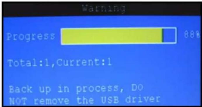
text_image
Warning Progress 88% Total:1,Current:1 Back up in process, DO NOT remove the USB driverNotes:
1) When free space on the backup device is less than the size of the file to back-up, the system will prompt "Space not enough"...
2) You can remove the USB device directly when backup is finished.

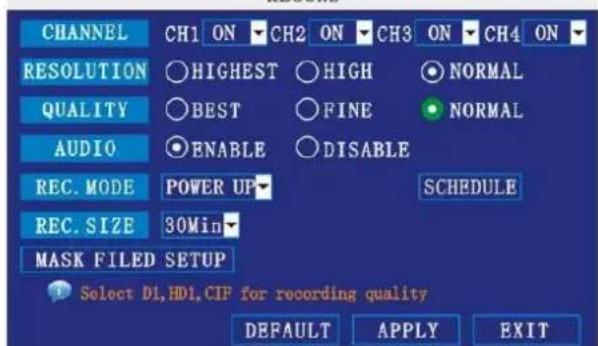
7.3.2 RECORD
Configure record parameters, enable/disable audio.
NOTE: Audio capable cameras (not included) are required for audio recording.
RECORD
text_image
CHANNEL CH1 ON CH2 ON CH3 ON CH4 ON RESOLUTION HIGHEST HIGH NORMAL QUALITY BEST FINE NORMAL AUDIO ENABLE DISABLE REC. MODE POWER UP SCHEDULE REC. SIZE 30Min MASK FILED SETUP Select D1,HDL,CIF for recording quality DEFAULT APPLY EXITFigure 2.4.2.3.1 Record
To configure recording options:
1) Under CHANNEL, use the drop-down menus and select ON/OFF to enable/disable recording from the selected channel.
2) Under RESOLUTION, select HIGHEST, HIGH, or NORMAL (corresponding to D1, HD1, CI F
resolution).
NOTE: PAL: D1@6fps, HD1@12fps, CIF@24fps / NTSC: D1@7fps, HD1@15fps, CIF@30fps
3) Under QUALITY, select BEST, FINE, NORMAL
CIF: corresponding to 384 Kbps and 512 Kbps and 768 Kbps.
HD1: corresponding to 512Kbps and 768Kbps and 1024Kbps.
D1: corresponding to 512Kbps and 768Kbps and 1024Kbps.
4) Under AUDIO, select ENABLE or DISABLE. If audio recording is enabled, the system will record audio from connected audio capable cameras (not included).
5) Under REC. MODE, select POWER UP or TIMER RECORD. If you select POWER UP, the system will record continuously (normal recording) when the system is powered on. If you select TIMER RECORD, you have to set a recording schedule on the system.
6) Under REC. SIZE, select 15MIN, 30MIN, 45MIN, or 60MIN.
NOTE: Record size sets the file size for recorded video files on the system. Instead of recording data as one large file, the system will divide the data into blocks of 15, 30, 45, or 60 minutes. This makes the recorded data easier to search.
7) Click APPLY. Click SURE in the confirmation window.
8) Click EXIT in every menu until all windows are closed.
Recording Schedule
By default, the system is set to record continuously, 24 hours a day, 7 days a week. You can program the system to record according to a customized recording schedule.
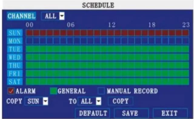
text_image
SCHEDULE CHANNEL ALL 00 06 12 18 23 SUN MON TUE WED THU FRI SAT ✓ ALARM GENERAL MANUAL RECORD COPY SUN TO ALL COPY DEFAULT SAVE EXITFigure 2.4.2.3.1 Recording Schedule
The schedule grid shows the days of the week and hours 0\~23. You can set ALARM recording (red), GENERAL (normal) recording (green), or MANUAL recording (blue) for each time block of each day.
To set a recording schedule:
1) Open the Main Menu and click RECORD.
2) Under REC. MODE, select TIMER RECORD.
3) Click SCHEDULE. The Schedule menu opens.
4) Under CHANNEL, select specific channels or select ALL.
5) Below the grid, click either ALARM (red), GENERAL (green), or MANUAL RECORD (blue) and then click a time block on the desired day.
6) Use the FROM/ TO drop-down menus to copy the schedule of one day to another.
For example, if you want your schedule for Monday to be the same on Wednesday: under FROM select MON, under TO select WED, and then click COPY.
7) Click SAVE.
8) Click EXIT in each menu until all windows are closed.
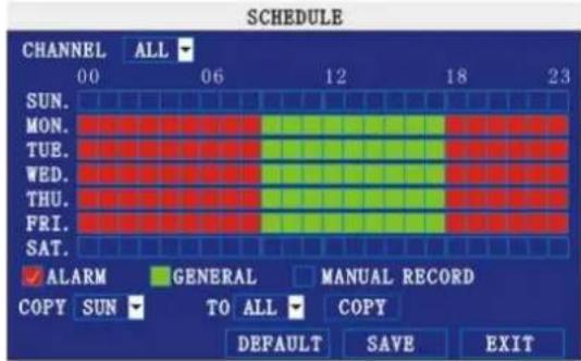
Example
You want your system to record continuously on all channels from 9 AM to 5 PM Monday to Friday. You also want Alarm/Motion recording from 5 PM to 9 AM. You do not want the system to record Saturday or Sunday.
To set the recording schedule:
1) Open the Schedule menu.
2) Under CHANNEL, select ALL.
3) Click the blue MANUAL RECORD block below the grid. A checkmark will appear in the block.
4) Under SUN, click blocks 00\~23. The blocks will turn blue.
5) Under FROM, select SUN. Under TO select SAT, and then click COPY.
6) Click the red ALARM block below the grid.
7) Under MON, click blocks 00\~08 and blocks 18\~23. The blocks will turn red.
8) Click the green GENERAL block below the grid.
9) Under MON, click blocks 09\~17. The blocks will turn green.
10) Under FROM, select MON. Under TO select TUE, and then click COPY. Repeat for Wednesday, Thursday, and Friday. Your completed schedule should the same as the image below:
CCTVSET10
text_image
SCHEDULE CHANNEL ALL 00 06 12 18 23 SUN. MON. TUE. WED. THU. FRI. SAT. ✓ ALARM GENERAL MANUAL RECORD COPY SUN TO ALL COPY DEFAULT SAVE EXIT11) Click SAVE. Click CLOSE in the confirmation window.
12) Click EXIT in all menus until all windows are closed.
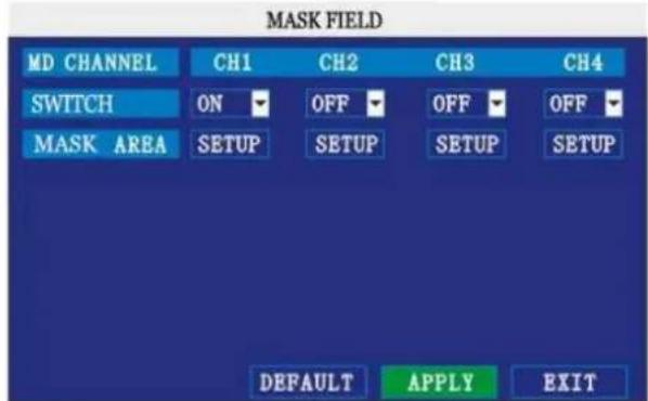
Mask Field Setup
The Mask Field lets you block a specific portion of a channel you do not want recorded or shown on the display screen. This can be useful if you need to conceal a sensitive area being captured by the installed camera.
text_image
MASK FIELD MD CHANNEL CH1 CH2 CH3 CH4 SWITCH ON OFF OFF OFF MASK AREA SETUP SETUP SETUP SETUP DEFAULT APPLY EXITTo use the mask field:
1) From the Record menu, click MASK FIELD SETUP. The Mask Field menu opens.
2) Choose a channel you wish to apply the Mask Field. Select ON from the SWITCH drop-down menu.
3) Click SETUP. The Mask Menu disappears and the select channel is shown in full-screen.
4) Using the mouse, click and drag the cursor over the area you want to conceal. A single click will produce a small black square.
5) Right-click anywhere on the screen to return to the Mask Field menu.
6) Click APPLY. Click SURE in the confirmation window.
7) Click EXIT in all menus until all windows are closed.
7.3.3 HDD
Displays essential information about the system's internal hard drive, and lets you format the internal HDD and external USB flash drive (not included).
text_image
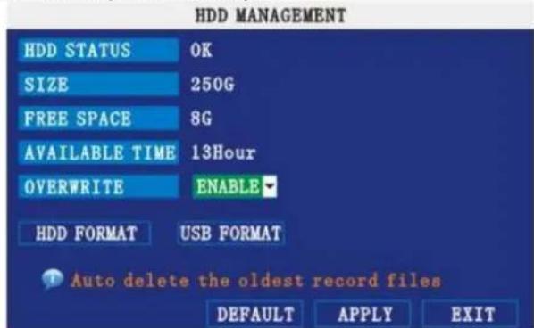
HDD MANAGEMENT HDD STATUS OK SIZE 250G FREE SPACE 8G AVAILABLE TIME 13Hour OVERWRITE ENABLE HDD FORMAT USB FORMAT Auto delete the oldest record files DEFAULT APPLY EXITThe HDD menu displays the following:
- HDD STATUS: The system will display "OK" for normal operation
- SIZE: The size (in gigabytes) of the internal hard disk drive.
- FREE SPACE: The space (in gigabytes) remaining on HDD
- AVAILABLE TIME: The recording time (in hours) remaining on the HDD based on your current record settings
- OVERWRITE: Select ENABLE or DISABLE. If overwrite is enabled, the system will record over the oldest video data once the HDD is full. If overwrite is disabled, the system will stop recording once the HDD is full and the live screen will show "H" symbol.
Formatting the Hard Drive
- Click on HDD FORMAT.
ATTENTION: Formatting the HDD will erase all video data. This step cannot be undone.
Formatting the USB Flash Drive
- Use a USB flash drive (not incl.) to backup recorded video and upgrade the systems firmware. You should always format the USB flash drive you intend to use with the system.
NOTE: Not formatting the USB flash drive may result in improper functionality.

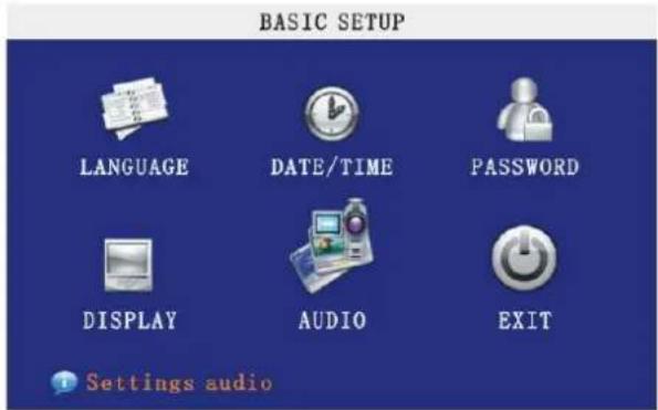
7.3.4 BASIC
Set the system language, date and time, passwords, and configure audio and display options. The Basic Setup menu contains the following sub-menus: Language, Date/ Time, Password, Display, and Audio.
text_image
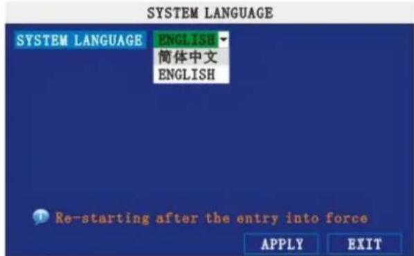
BASIC SETUP LANGUAGE DATE/TIME PASSWORD DISPLAY AUDIO EXIT Settings audio7.3.4.1 LANGUAGE
text_image
SYSTEM LANGUAGE SYSTEM LANGUAGE ENGLISH 简体中文 ENGLISH Re-starting after the entry into force APPLY EXITTo change the system language:
1) From the drop-down menu select ENGLISH, or CHINESE.
2) Click APPLY. Click SURE in the confirmation window.
3) Click EXIT to close the menu.
NOTE: The device will restart when you finish system language setup.
7.3.4.2 DATA/TIME
It is highly recommended to immediately set the date and time when first setting up your system.
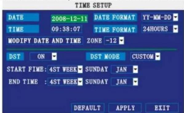
text_image
TIME SETUP DATE 2008-12-11 DATE FORMAT YY-MM-DD TIME 09:38:07 TIME FORMAT 24HOURS MODIFY DATE AND TIME ZONE -12 DST ON DST MODE CUSTOM START FIME: 4ST WEEK SUNDAY JAN END TIME : 4ST WEEK SUNDAY JAN DEFAULT APPLY EXITTo set the date and time:
1) Click DATE/ TIME and configure the following options:
- DATE: Enter the day, month, and year.
- DATE FORMAT: Select DD/ MM/ YYYY, MM/ DD/ YYYY, or YYYY/ MM/ DD
- TIME: Enter the time
- TIME FORMAT: Use the drop-down menu and select 12HOURS or 24HOURS
o DST: Use the drop-down menu to select ON/OFF to enable/disable Daylight Savings Time
2) Click MODIFY DATE AND TIME. Click SURE in the confirmation window.
3) Click APPLY. The new date and time are saved.
Daylight Savings Time
To set daylight savings time:
1) Under DST, select ON. DST options appear.
2) Under DST MODE select one of the following:
CUSTOM: Set customized start and end times for DST (go to step 4)
- DEFAULT: The Default setting will apply DST from the second Sunday of March to the second Sunday in November (go to step 3)
3) If using the DEFAULT, click APPLY.
4) If setting a CUSTOM DST, use the drop-down menus to select a week and month for the start and end times.
5) Click APPLY. Click SURE in the confirmation window.
6) Click EXIT in each menu until all windows are closed.
7.3.4.3 PASSWORD
When you first start up your system, you are technically logged in as the ADMIN under Device ID000000. The system allows two user authorities connected to a Device ID. The authorities are as follows:
○ ADMIN—administrator: has full control of the system, and can change both administrator and user passwords and enable/disable password checking
- USER—normal user: only has access to live viewing, search, playback, and other limited authorities.
For security reasons, it is highly recommended to enable passwords on your system. If you enable passwords, you must select a 6-digit USER password and a 6-digit ADMIN password.
ATTENTION:
By default, passwords are disabled on the system. You will not need a password to log in or access menus. You will not need a password to access your system using the browser-based remote software.
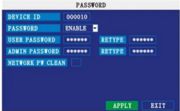
text_image
PASSWORD DEVICE ID 000010 PASSWORD ENABLE USER PASSWORD ***** RETYPE ***** ADMIN PASSWORD ***** RETYPE ***** NETWORK PW CLEAN APPLY EXITYou can change the Device ID and password of the ADMIN and the USER from the Password menu.
To open the Password/security menu:
1) Right-click anywhere onscreen to open the Sub-Menu and select MAIN MENU.
2) Click BASIC. The Basic Setup Menu opens.
3) Click PASSWORD. The Password/Security menu opens.
To change your Device ID and Password:
1) Click the field beside DEVICE ID and enter a 6-digit numerical Device ID using the Virtual Keyboard (mouse only). For example, change the ID to 000010.
2) Under PASSWORD, select ENABLE.
3) Click the field beside USER PASSWORD to enter a 6-digit numerical password using the Virtual Keyboard (mouse only). Re-enter the password in the corresponding field.
4) Click the field beside ADMIN PASSWORD to enter a 6-digit numerical password using the Virtual Keyboard (mouse only). Re-enter the password in the corresponding field.
NOTE: The USER and ADMIN passwords must not be the same.
5) Click APPLY to save your changes. Click SURE in the confirmation window.
6) Click EXIT in each menu until all windows are closed.
Use your new password to log in to the system and access system menus. You can also use the USER and ADMIN passwords to access your system using the browser-based remote software.
NETWORK PW CLEAN: select and click APPLY will initialize the IE browser password.
7.3.4.4 DISPLAY
Use the Display Setup menu to customize channel titles, show/hide the date and time in live viewing and playback, and enable/disable preview channels.
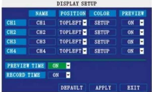
text_image
DISPLAY SETUP NAME POSITION COLOR PREVIEW CH1 CH1 TOPLEFT SETUP ON CH2 CH2 TOPLEFT SETUP ON CH3 CH3 TOPLEFT SETUP ON CH4 CH4 TOPLEFT SETUP ON PREVIEW TIME ON RECORD TIME ON DEFAULT APPLY EXITTo customize Display settings:
1) Configure the following options:
○ NAME: click any of the fields and enter a new title for the selected channel using the Virtual Keyboard (mouse only)
o POSITION: reposition the channel title; select TOPLEFT, BOTTOMLEFT, TOPRIGHT, BOTTOMRIGHT or OFF. If OFF, the title will not be displayed for the selected channel
- COLOR: Adjust CHROMATICITY, LUMINOSITY, CONTRAST, and SATURATION for the selected channel
o PREVIEW TIME: select ON/ OFF to show/ hide the date and time during live viewing
- RECORD TIME: select ON/ OFF to show/hide the date and time during playback.
2) Click NEXT PAGE to change the settings for the remaining channels (8-channel models only).
3) Click APPLY to save your settings. Click SURE in the confirmation window.
Preview
Preview channels can be very useful if your display monitor is in public view. Select OFF of a preview channel will appear black on the display to give the impression that no cameras are connected and the system is not recording.
To enable/disable preview channels:
1) Choose a channel you wish to conceal. For example, channel 3. Under PREVIEW, select OFF.
2) Click APPLY. Channel 3 will turn black. Click CLOSE in the confirmation window.
3) Click EXIT in all menus until al windows are closed.
7.3.4.5 AUDIO
Use the Audio menu to set the resolution and camera system on the system.
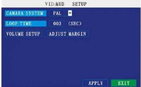
text_image
VID/AUD SETUP CAMARA SYSTEM PAL LOOP TIME 003 (SEC) VOLUME SETUP ADJUST MARGIN APPLY EXITTo configure video options:
1) Under CAMERA SYSTEM, select NTSC or PAL.
2) Click APPLY. Click CLOSE in the confirmation window.
3) Click EXIT in all menus until all windows are closed.
To configure audio options:
1) From the Audio menu, click VOLUME SETUP. A split-screen display view appears.
2) Click any channel and adjust the slider to increase/decrease the volume for listen-in audio.
3) Click X to return to the Audio menu.
4) Click APPLY. Click SURE in the confirmation window.
5) Click EXIT in all menus until all windows are closed.
LOOP TIME:
1) Click the input box to set.
2) Left click to exit, Click SURE in the confirmation window.
3) Click EXIT in all menus until all windows are closed.

7.3.5 ADVANCE
Use the advanced setup menu to configure alarm settings, motion detection, mobile surveillance, PTZ settings and network settings. The advanced setup menu contains the following sub-menus: Alarm, Info, MD, Mobile, System, PTZ, and Network.
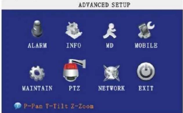
text_image
ADVANCED SETUP ALARM INFO MD MOBILE MAINTAIN PTZ NETWORK EXIT P-Pan T-Tilt Z-Zoom7.3.5.1 ALARM
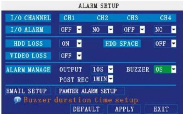
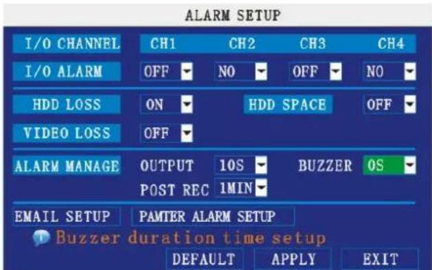
Use the Alarm menu to configure alarm and email settings.
text_image
ALARM SETUP I/O CHANNEL CH1 CH2 CH3 CH4 I/O ALARM OFF NO OFF NO HDD LOSS ON HDD SPACE OFF VIDEO LOSS OFF ALARM MANAGE OUTPUT 10S BUZZER OS POST REC 1MIN EMAIL SETUP PAMTER ALARM SETUP Buzzer duration time setup DEFAULT APPLY EXITI/O Alarm: each channel has one I/O alarm. When an alarm is triggered the corresponding channel will start alarm record.
NO (Normal Open, when alarm in, close)
OFF (Normal Closed, when alarm in, open)
HDD LOSS: The alarm will sound if the internal HDD is damaged. The live screen will show [H].
HDD SPACE: when the space less then 500MB, the live screen will show 'not enough space'. Clear data or replace HDD.
VIDEO LOSS: when a camera is disconnected, the live screen will show 'video loss'.
ALARM MANAGE:
• alarm output: set the time of alarm output: 0, 10, 20, 40 or 60 seconds.
- Buzz: set the time of buzz: 0, 10, 20, 40 or 60 seconds.
- post record: set the record time after alarm: 30 Sec, 1, 2 or 5 Min.
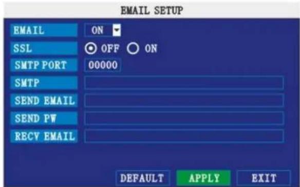
EMAIL SETUP:
The system can send an email notification with a JPEG snapshot for triggered events on the system every 3 minutes.
text_image
EMAIL SETUP EMAIL ON SSL OFF ON SMTP PORT 00000 SMTP SEND EMAIL SEND PW RECV EMAIL DEFAULT APPLY EXITTo setup email notification:
1) Under EMAIL, select ON.
2) Under SSL, select OFF.
NOTE: SSL deals with encryption. Only advanced users should enable this option.
CCTVSET10
3) Under SMTP PORT, enter the SMTP port of your email server.
4) Under SMTP, enter the SMTP address of your email server. For example, smtp.gmail.com
5) Under SEND EMAIL, enter the sender email address.
6) Under SEND PW, enter the password of your email server.
7) Under RECV EMAIL, enter the email address that will receive the email notification.
8) Click APPLY. Click SURE in the confirmation window.
9) Click EXIT in all menus until all windows are closed.
7.3.5.2 INFO
View system information, including the firmware version, MAC address, and serial number of the system.
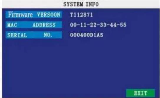
text_image
SYSTEM INFO Firmware VERSOON T112871 MAC ADDRESS 00-11-22-33-44-55 SERIAL NO. 000400D1A5 EXIT7.3.5.3 MD (MOTION DETECT)
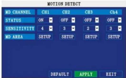
Configure motion detection for each channel.
text_image
MOTION DETECT MD CHANNEL CH1 CH2 CH3 Ch4 STATUS ON OFF OFF OFF SENSITIVITY 4 3 2 3 MD AREA SETUP SETUP SETUP SETUP DEFAULT APPLY EXITTo configure motion detection:
- Under STATUS, select ON to enable motion detection for the desired channel. Click NEXT PAGE for additional channels (8-channel models only).
- Under SENSITIVITY, select 1, 2, 3, or 4. The higher the number, the more sensitive the motion detection.
- Under MD SETUP, click SETUP. The red motion grid appears over the selected channel in full screen.
- Click the blocks in the grid to enable/disable motion detection. Red=motion detection enabled; Clear=motion detection disabled.

natural_image
Grid pattern with a small white square on the left and a red square on the right, no text or symbols present.• Right-click anywhere on the screen to return to the Motion Detection menu.
- Click APPLY. Click SURE in the confirmation window.
- Click EXIT in all menus until all windows are closed.
NOTE: You can disable the MD buzzer in the alarm setup menu.
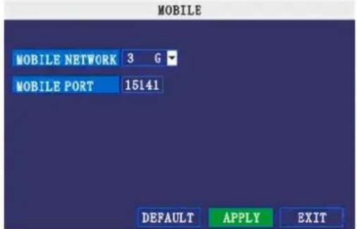
7.3.5.4 MOBILE
Send alerts to your cellular phone Windows Mobile enabled touch-screen smart phone (Windows Mobile 6.0 or greater, S60 3 ^rd generation or greater is required).
text_image
MOBILE MOBILE NETWORK 3 G MOBILE PORT 15141 DEFAULT APPLY EXITTo configure mobile notification settings:
1) Under MOBILE NETWORK, select 3G,2.75G, or 2.5G.
NOTE: Contact your cellular provider if you are unsure about the network of your cellular phone.
2) Under MOBILE PORT, enter your mobile port number.
3) Click APPLY. Click SURE in the confirmation window.
4) Click EXIT in all menus until all windows are closed.
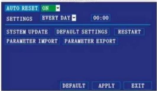
7.3.5.5 MAINTAIN
Use the System menu to update system firmware and set an automatic system reset schedule.
SYSTEM MAINTAIN
text_image
AUTO RESET ON SETTINGS EVERY DAY 00:00 SYSTEM UPDATE DEFAULT SETTINGS RESTART PARAMETER IMPORT PARAMETER EXPORT DEFAULT APPLY EXITTo enable auto-reset:
1) Under AUTO RESET, select ON. The Settings option appears.
2) Under SETTINGS, select EVERY DAY, EVERY WEEK, or EVERY MONTH. The date drop-down menu appears.
3) Select the date for auto-reset from the drop-down menu.
4) Enter the time for auto-reset using the virtual keyboard (mouse only).
5) Click APPLY. Click SURE in the confirmation window
To restore factory settings:
1) Click DEFAULT SETTINGS. This will restore the system to the original factory settings.
2) Click OK in the prompt.
NOTE: Recorded video on the HDD will not be erased.
To restart the machine (soft-reset):
1) Click RESTART.
2) Click OK in the prompt. The system will perform a soft-reset and load to a live split-screen view.
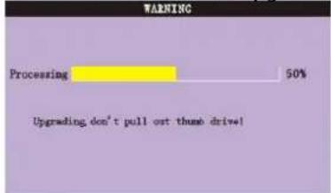
To upgrade firmware:
1) Copy the firmware file to an empty USB flash drive. The firmware file should not be in a folder.
2) Connect the USB flash drive to the USB port on the front panel of your system.
3) Open the System Menu (Main Menu>Advance>Maintain).
4) Click FIRMWARE UPDATE. The system will scan the USB flash drive and begin updating the firmware. Do not remove the USB flash drive while the upgrade is taking place.
text_image
WARNING Processing 50% Upgrading don't pull out thumb drive!5) Click SURE in the confirmation window. In the system prompt, click OK. The system will restart.
PARAMETER EXPORT: Copy the system settings of the device to an empty USB flash drive.
PARAMETER IMPORT: Import system settings from another device.
7.3.5.6 PTZ
Use the PTZ Setup menu to configure settings for a connected PTZ camera (not included).
NOTE: Consult the instruction manual of your PTZ camera for complete information about your camera, including protocol and baud rate.
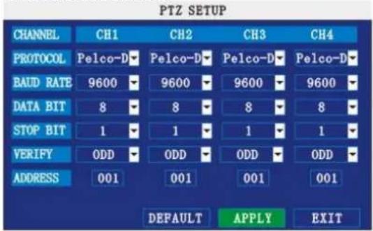
text_image
PTZ SETUP CHANNEL CH1 CH2 CH3 CH4 PROTOCOL Pelco-D Pelco-D Pelco-D Pelco-D BAUD RATE 9600 9600 9600 9600 DATA BIT 8 8 8 8 STOP BIT 1 1 1 1 VERIFY ODD ODD ODD ODD ADDRESS 001 001 001 001 DEFAULT APPLY EXITTo configure a PTZ camera:
1) Connect a PTZ camera to the BNC and 485A (TX, +) and 485B (RX, -) ports and power outlet. For more details on connecting a PTZ camera.
2) Under PROTOCOL, select PELCO-D or PELCO-P for the selected channel. Click NEXT PAGE for additional channels (8-channel models only).
3) Under BAUD RATE, select 1200, 2400, 4800, or 9600.
4) Under DATA BIT select 5, 6, 7, or 8.
5) Under STOP BIT, select 1 or 2.
6) Under VERIFY, select ODD, EVEN, MARK, SPACE, or NONE.
7) Under ADDRESS, enter an address from 001\~255 using the Virtual Keyboard. Refer to your PTZ camera's instruction manual for further details.
8) Click APPLY. Click CLOSE in the confirmation window.
9) Click EXIT in all menus until all windows are closed.
7.3.5.7 NETWORK
Use the Network Setup menu to configure your network and DNS settings.
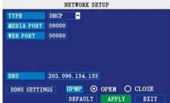
text_image
NETWORK SETUP TYPE DHCP MEDIA PORT 09000 WEB PORT 00080 DNS 202.096.134.133 DDNS SETTINGS UPNP OPEN CLOSE DEFAULT APPLY EXITFigure 2.4.2.18.1 network setup
UPNP
UPnP Forum is an industry initiative designed to enable simple and robust connectivity among consumer electronics, intelligent appliances and mobile devices from many different vendors. NOTE: the router needs to support UPNP function.
To configure UPNP settings:
1) Enable the UPNP function in your Router.
2) Under DVR GUI, Open the MAIN MENU and click ADVANCE.
3) From the Advanced Setup menu, click NETWORK.
4) Under UPNP, select OPEN.
5) Click APPLY to save your settings and then click OK in the confirmation window.
6) Using a remote PC, open Internet Explorer.
7) In the address bar, enter your Router WAN IP address immediately followed by: WEB PORT (no spaces).
http://XXX.XXX.XXX.XXX(Router WAN IP):XXX(WEB PORT)
8) Enter your system ADMIN password and select INTERNET.
NOTE: If you have not enabled passwords on the system, leave the password field blank.
9) Click LOGIN.
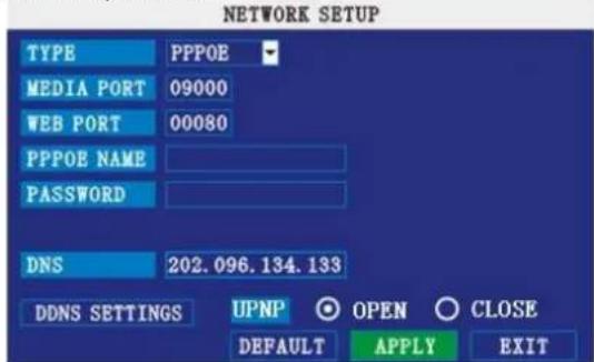
To configure network settings:
1) Under TYPE, select DHCP, PPPoE, or STATIC.
If DHCP, go to step 5. If PPPoE, go to step 2, if STATIC, go to step 3.
NOTE: DHCP allows you to quickly connect to your network by obtaining an IP address from the router. After the initial setup, we recommend that you disable DHCP and set the IP address between 1\~100. For example, if your IP address is 192.168.0.107, change the last digits to 90 (i.e. 192.163.0.90). This ensures that port forwarding will not change in the event of power failure or resetting of your network.
CCTVSET10
2) If you select PPPoE in step 1, enter your PPPoE user name and password in the respective fields using the Virtual Keyboard.
text_image
NETWORK SETUP TYPE PPPOE MEDIA PORT 09000 WEB PORT 00080 PPPOE NAME PASSWORD DNS 202.096.134.133 DDNS SETTINGS UPNP ○ OPEN ○ CLOSE DEFAULT APPLY EXIT3) If you selected STATIC in step 1, enter your IP Address, Net mask, and Gateway in the respective fields using the Virtual Keyboard.
NOTE: The default IP address of the system is 192.168.3.97
4) If necessary, change the Media and Web Ports.
NOTE: For added security, we strongly recommend changing Web port 80 on the system to any desired port not blocked by your Internet service provider (ISP). Please note however, that you will also need to update the Web port in your browser and open this new port in your router.
5) Click APPLY. Click SURE in the confirmation window.
6) Click EXIT in all menus until all windows are closed. The system restarts automatically.
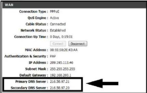
Manual DNS
Enter the Primary or Secondary DNS from your router. This is required for DDNS to function properly.
To obtain your Primary or Secondary DNS:
1) In your web browser, log in to your router using its Default Gateway address.
NOTE: Refer to your router's manual or software for login information. You can also get the Default Gateway on your PC by selecting Start>Run. Type CMD and press Enter. In the Command Prompt window type ipconfig and press Enter.
2) View its WAN settings. Enter the Primary or Secondary DNS address in the MANUAL DNS field on your system.
text_image
WAN Connection Type: PPPoE QoS Engine: Active Cable Status: Connected Network Status: Established Connection Up Time: 0 Days, 0:15:01 Connect Disconnect MAC Address: 00:1E:58:2E:43:AA Authentication & Security: PAP IP Address: 209.195.113.46 Subnet Mask: 255.255.255.255 Default Gateway: 192.168.200.1 Primary DNS Server: 216.58.97.21 Secondary DNS Server: 216.58.97.20DDNS:
A DDNS account allows you to set up a web site address that points back to your Local Network.
NOTE: You must register DDNS service prior to configuring DDNS settings. Visit
https://www.dyndns.com/ to register.
text_image
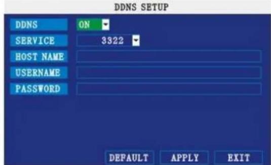
DDNS SETUP DDNS ON SERVICE 3322 HOST NAME USERNAME PASSWORD DEFAULT APPLY EXITTo configure DDNS settings:
1) From the Network Setup menu, enter Primary or Secondary DNS from the WAN settings of your router in the MANUAL DNS field.
2) Click DDNS SETTINGS.
3) Under DDNS, select ON.
4) Under SERVICE, select 3322, dyndns or perfecteyes.
5) Under DOMAIN NAME, enter your DDNS domain from the confirmation email.
CCTVSET10
For example, if your domain name is adam@dyndns.com, you need to enter adam@dyndns.com, in the text field.
6) Enter your DDNS user name and password in the respective fields.
7) Click APPLY. Click SURE in the confirmation window.
8) Click EXIT. The system will prompt you that it must restart. Click CLOSE.
8. Remote surveillance software
The system features built-in browser-based software that allows you to access your system remotely over your local area network (LAN) or over the Internet using Internet Explorer ^® .
NOTE: To ensure PC stability when browsing the DVR, recommended operating systems are Windows XP, Windows Vista, Windows 7; recommended browsers are IE 6.0, IE 7.0, IE 8.0.
8.1 Connecting
With your system connected to your local area network, you can now log in to your system using Internet Explorer.
NOTES:
- Your system must be connected to your local or wide area network before attempting remote access.
- You must configure DDNS settings locally.
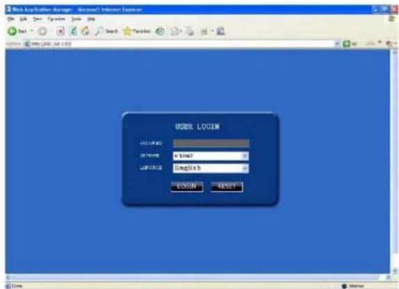
To access your system:
1) Open Internet Explorer. In the address bar, enter the IP address (and port when different from 8080) of your system (e.g. http://192.168.3.97:2563).
2) You must install ActiveX® in order to access your system. Click the attention bar at the top of the main page and select Install ActiveX Control. DVR Net viewer will reset.

text_image
Address http://192.168.0.102/ To help protect your security, Internet Explorer stopped this site from installing software on your computer. Click here for options... If your browser do not support to download the ActiveX control, please click here.3) In the warning box click Install. The login page appears.
4) Leave the password field blank (default).
NOTE: If you have enabled passwords on your system, enter your USER or ADMIN password. However, only the ADMIN can change settings and options on the system.
5) Select LAN or INTERNET from the drop-down menu and click LOGIN. The process will take about 1\~2 minutes.
text_image
Web Application Manager - Microsoft Internet Explorer USEX LOGIN HKEY: C:\WINDOWS\CSPC\Microsoft\English\BEGIN\BEGIN\BEGIN\BEGIN\BEGIN\BEGIN\BEGIN\BEGIN\BEGIN\BEGIN\BEGIN\BEGIN\BEGIN\BEGIN\BEGIN\BEGIN\BEGIN\BEGIN\BEGIN\BEGIN\BEGIN\BEGIN\BEGIN\BEGIN\BEGIN\BEGIN\BEGIN\BEGIN\BEGIN\BEGIN\BEGIN\BEGIN\BEGIN\BEGIN\BEGIN\BEGIN\BEGIN\BEGIN\ begin WIN: C:\WINDOWS\CSPC\CSPC\Microsoft\English\begin{array}{c}\begin{array}{c}\begin{array}{c}\begin{array}{c}\begin{array}{c}\begin{array}{c}\begin{array}{c}\begin{array}{c}\begin{array}{c}\begin{array}{c}\begin{array}{c}\begin{array}{c}\begin{array}{c}\begin{array}{c}\begin{array}{c}\begin{array}{c}\begin{array}{c}\begin{array]{c}\begin{array}{c}\begin{array}{c}\begin{array}{c}\begin{array}{c}\begin{array}{c}\begin{array}{c}\begin{array}{c}\begin{array}{c}\begin{array}{c}\begin{array}{c}\begin{array}{c}\begin{array}{c}\begin{array}{c}\begin{array}{c}\begin{array}{c}\begin{array}{c}\begin{\array}{c}\begin{array}{c}\begin{array}{c}\begin{array}{c}\begin{array}{c}\begin{array}{c}\begin{array}{c}\begin{array}{c}\begin{array}{c}\begin{array}{c}\begin{array}{c}\begin{array}{c}\begin{array}{c}\begin{array}{c}\begin{array}{c}\begin{array}{c}\begin{array}{c}10000000000000000000000000000000000000000000000000000000000000000000000000000000000000000000000000000\\end{array}\\156789999999999999999999999999999999999999999999999999999999999999999999999999999999999999999999999999999 \end{array} \end{array} \end{array} \end{array} \end{array}8.2 Remote surveillance main screen
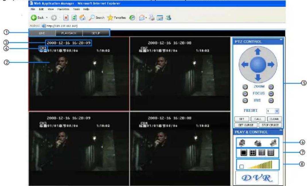
Upon login, the Remote Surveillance main screen appears in your browser.
text_image
Web Application Manager - Microsoft Internet Explorer File Edit View Favorites Tools Help Back Search Favorites Address https://139.137.112.187/ LIVE PLAYBACK SETUP ① 2008-12-16 16:28:09 CH1 标准01/01章节05/04 1:18:02 2008-12-16 16:28:08 CH2 标准01/01章节05/04 1:18:02 PTZ CONTROL ZOOM FOCUS IRIS PRESET 1 SET CALL CLEAN SET CURSE STOP-CRUST PLAY & CONTROL ⑥ ⑦ ⑧ DVR1) Modes: Click LIVE, PLAYBACK or SETUP.
2) Main Screen: Main display screen for live viewing and playback.
3) Time Stamp: Time stamp appears on each channel.
4) Channel: Channel number appears in the top left corner.
5) PTZ Control: PTZ control for any connected PTZ cameras (not included).
6) Functions: Click the icons to show/hide channels, take screen captures, and record.
7) Display Modes: Click the icons to view channels in single-channel full-screen, quad, and split-screen configurations.
8) Volume/ Mute: Select a channel (outlined in red) and then click the bars to increase/decrease volume; click the icon to mute/un-mute volume.*
*Audio capable cameras (not included) required for audio listening and recording.
8.2.1 Live viewing
By default, remote surveillance opens in Live Viewing mode (split-screen).
To use Live Viewing:
1) Click LIVE at the top of the main screen.
2) Click the display mode icons to view the main screen in single-channel, quad, or split-screen configurations. You can also double-click a channel at any time to view it in single-channel.
3) Click to show or hide all the channel windows.
4) Click to start/stop manual recording to your PC on ALL channels. For more details see RECORDING.
5) Select a channel (outlined in red) and then click the audio bars to increase or decrease listen-in volume*. Click the icon to mute/un-mute.
NOTE: The Talk function is not supported.
*Audio capable camera (not included) required for listen-in audio.
8.2.1.1 RECORDING

You can record video directly to your PC using the remote surveillance software.
To record video to your PC:
From Live viewing, click to start/stop manual recording to your PC on ALL channels
NOTES:
- You will record video to your PC regardless of the recording mode on the system itself.
- By default, recorded files are saved in C:\DVR[ip_address]\Record.
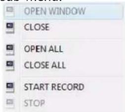
8.2.1.2 SUB-MENU
Right-click any channel to open the sub-menu.
text_image
OPEN WINDOW CLOSE OPEN ALL CLOSE ALL START RECORD STOPThe sub-menu contains the following options:
- Open Window
- Close
- Open All
- Close All
- Start Record
- Stop
8.2.1.3 PTZ CONTROL
You must have a PTZ camera (not included) connected to the system in order to use the PTZ controls.
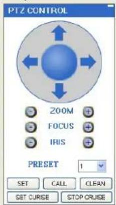
text_image
PTZ CONTROL 200M FOCUS IRIS PRESET 1 SET CALL CLEAN SET CURISE STOP CRUISETo control a PTZ camera:
1) Select the channel of the connected PTZ camera(s).
2) Click the navigation arrows to pan and tilt the camera. 3. Click + / - to control zoom, focus, and iris.
3) Enter presets.
4) Click SETTING, CALL, and CLEAR to further control presets.
5) SET CRUISE: Set the parameter for loop function.
6) STOP CRUISE: Stop loop function.
8.2.1.4 SCREEN CAPTURES
Use the remote surveillance software to take a snapshot of the channels on the main display screen. Screen Captures can be useful for your own records, or may be needed by authorities in case of a security incident.
To take a screen capture:
1) From Live Viewing, select the channel you want to capture. The selected channel will be highlighted in a red frame.
2) Click.

3) Click OK in the confirmation window. Screen captures are saved as .BMP files on the default save location (C:\DVR...).
8.2.2 PLAYBACK
Use the Replay menu to search and playback recorded video on your system.
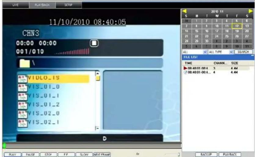
text_image
11/10/2010 08:40:05 CHN3 00:00 00:00 001/010 \VIDLO_IS VIS_01_0 VIS_01_1 VIS_01_2 VIS_02_0 VIS_02_1 D 20:10 11 S M T W T F S 31 1 2 3 4 5 6 7 8 9 10 11 12 13 11 13 16 17 18 19 20 21 22 23 24 25 26 27 28 29 30 3 2 3 4 5 6 7 8 9 10 11 ALL ALL TYPE SEARCH FILE LIST TIME CHANN... SIZE ▶08:40:01:08:4 3 4.64 ◀08:40:01:08:4... 4 4.64 BALCLIP PLAYBACKTo use the replay menu:
1) Click PLAYBACK at the top of the main screen. The main screen will be grey.
2) Click REFRESH below the calendar to view the recorded files for the current month.
NOTE: Normal recording is indicated by a clock icon; alarm recording (alarm, loss, and motion events) are indicated by an exclamation mark icon.
3) Double-click a file from the File List to playback the file in the main screen. The icon in the file list changes to "▶Control playback using the buttons at the bottom of the main screen.

text_image
PLAY PAUSE STOP F.F. SLOW NEXT FRAME 0xThe purple bar indicates the download progress. The green marker indicates playback progress. You can click and drag the playback marker (will turn from green to orange) to advance or rewind playback as needed.
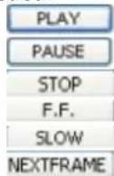
Play
Pause
Stop play
Fast play
Slow play
Pause at next frame
SEARCH
Use the calendar and drop-down menus to search for recorded video on your system.
1) Click < > to change the month on the calendar. Dates with recorded video data will appear in bold.
2) Click the date. Recorded video files will populate the file list.
3) From the channel drop-down menu, select a specific channel or select ALL CHANNEL and then click SEARCH.
4) From the type drop-down menu, select COMMON (normal recording), ALARM, or ALL TYPE and then click SEARCH.
5) Double-click the file from the File List to playback the file in the main screen.
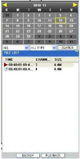
text_image
2010 11 S M T W I F S 31 1 2 3 4 5 6 7 8 9 10 11 12 13 14 15 16 17 18 19 20 21 22 23 24 25 26 27 28 29 30 1 2 3 4 5 6 7 8 9 10 11 ALL ✓ ALL TYPE ✓ SEARCH FILE LIST TIME CHANNEL... SIZE 09:40:01 09:4... 3 4.4M 09:40:01-09:4... 4 4.4M BACKUP PLAYBACKREMOTE BACKUP
You can backup recorded video files from your system to your PC using the Replay menu in the remote surveillance software.
To backup files remotely:
1) Click REPLAY at the top of the main screen.
2) Select a date(s) on the calendar and click REFRESH.
3) Double-click a file from the File List to begin playback.
4) Click BACKUP. Backup begins to C:/DVR/[ip_address]/Backup
NOTE: If you playback a file, you must wait for the file to load before backing it up otherwise you may receive an error message
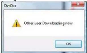
text_image
Other user Downloading now OK5) When file backup is complete, click OK in the confirmation window. The confirmation window show the save path of the backup file.
NOTE: Backup files are saved as .264 files.
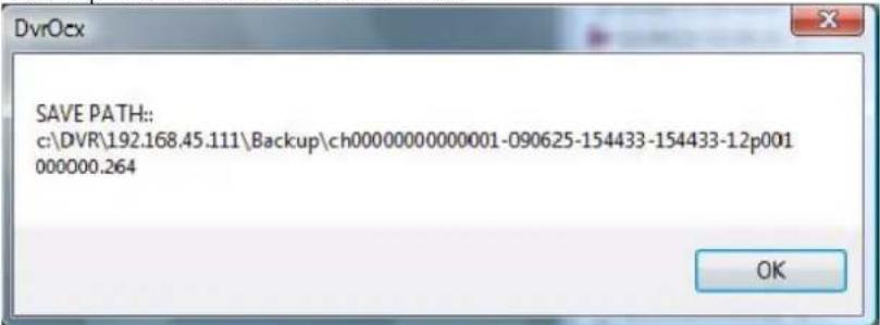
text_image
SAVE PATH:: c:\DVR\192.168.45.111\Backup\ch00000000000001-090625-154433-154433-12p001 000000.264NOTE: Use the player software included on the software CD to playback backed up video.
8.2.3 REMOTE SETUP
Use the Setup tab to configure the settings of your system from a remote location.
NOTE: If the main menu is open on the system, you will not be able to make changes to the system from the remote location.
To open remote setup:
Click SETUP at the top of the main screen. The Remote Setup menu features the following tabbed options:
- RECORD
- ALARM
• PTZ - NETWORK
- SETTING
- MAINTENANCE
- HOST INFO
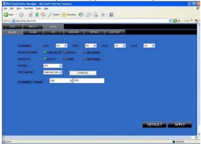
8.2.3.1 RECORD
Click RECORD to enter into setup interface; you can check the parameter settings as in GUI of DVR.
text_image
Web Application Manager - Microsoft Internet Explorer ON OR None Preferences Tools CHS Back Search Favorites Options http://192.368.3.97 UVE REPLAY SETUP RECORD ALARM FFT NETWORK SETTING ROOT INFO CHANNEL ON CHS ON CHS ON CHS ON RESOLUTION HIGHEST HIGH NORMAL QUALITY BEST FINE NORMAL AUDIO OFF REC MODE SNR RECORD SCHEDULE CHANNEL NAME CHS CHS DEFAULT APPLY Score8.2.3.2 ALARM SETTING
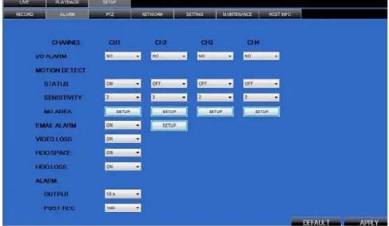
Click ALARM to enter into setup interface; you can check the parameter settings as in GUI of DVR.
text_image
OFF RECORD ALARM PTZ NETWORK SETTING MAINTENANCE HOST INFO CHANNEL CH1 CH2 CH3 CH4 I/O ALARM NO NO NO NO MOTION DETECT STATUS ON OFF OFF OFF SENSITIVITY 2 2 2 2 MO AREA SETUP SETUP SETUP SETUP EMAIL ALARM ON SETUP VIDEO LOSS ON HOD SPACE ON HOD LOSS ON ALARM OUTPUT 10 s POST REC LOAD DEFAULT APPLY8.2.3.3 PTZ
Click PTZ to access setup interface; you can check the parameter settings in GUI of DVR.
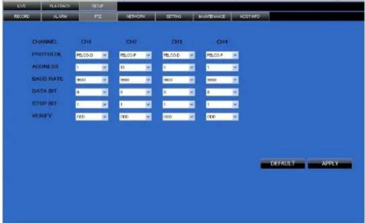
text_image
LIVE PLAYBACK SETUP RECORD ALIGN PTC NETWORKS SETTING MAINTENANCE HOST INFO CHANNEL CH1 CH2 CH3 CH4 PROTOCOL PELOD PELOP PELOD PELOP ADDRESS 1 10 1 1 SAUD RATE 9000 9000 9000 9000 DATA BIT 8 9 8 8 STOP BIT 1 1 1 1 VERIFY 000 000 000 000 DEFAULT APPLY8.2.3.4 NETWORK
Click NETWORK to access setup interface; you can check the parameter settings in GUI of DVR.
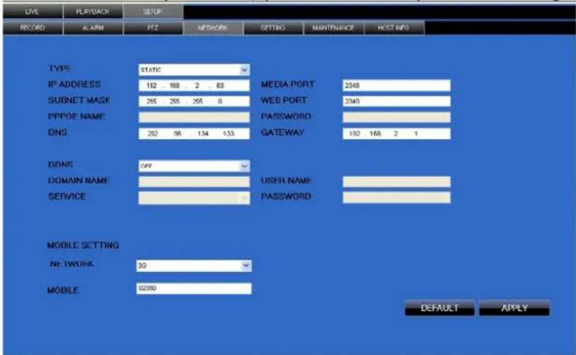
text_image
LIVE PLAYBACK SETUP RECORD ALARM PZ NETWORK SETTING MAINTENANCE HOST INFO TYPE: STATIC IP ADDRESS 192 188 2 83 SUBNET MASK 265 265 255 8 PPPDE NAME 202 96 134 133 MEDIA PORT WEB PORT PASSWORD GATEWAY 2348 2340 192 168 2 1 DDNS OFF DOMAIN NAME USER NAME SERVICE PASSWORD MOBILE SETTING NETWORK 30 MOBILE 02390 DEFAULT APPLY8.2.3.5 SETTING
Click SETTING to access setup interface; you can check the parameter settings in GUI of DVR
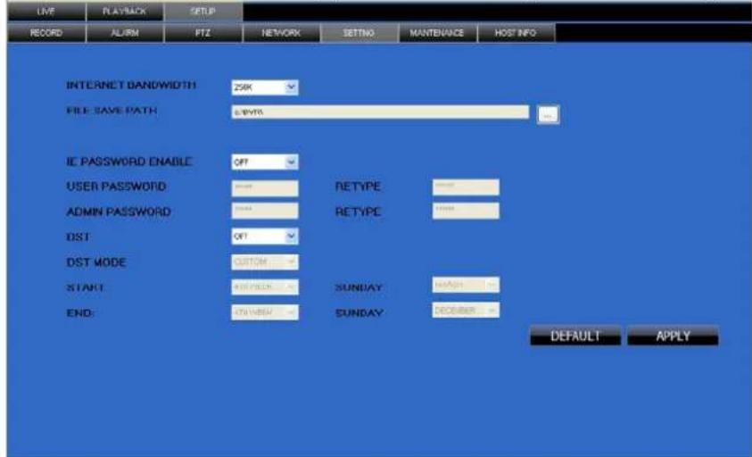
text_image
LIVE PLAYBACK SETUP RECORD ALARM PTZ NETWORK SETTING MANutenance HOST INFO INTERNET BANDWIDTH 254K FILE SAVE PATH 6.8V/30 IE PASSWORD ENABLE OFF USER PASSWORD RETYPE ADMIN PASSWORD RETYPE DST: OFF DST MODE CUSTOM START: SUNDAY END: SUNDAY DEFAULT APPLYBANDWIDTH: Set the bandwidth in kbps (128k, 192k, 256k, 384k, 512k, 1024k) that you want to allocate for traffic that matches the internet. This bandwidth does not include audio.
FILE SAVE PATH: the save path of captured picture and recording video.IE login password and DST settings you can set as DVR setting.
8.2.3.6 MAINTENANCE
Click MAINTENANCE to remotely reboot and remote upgrade here.
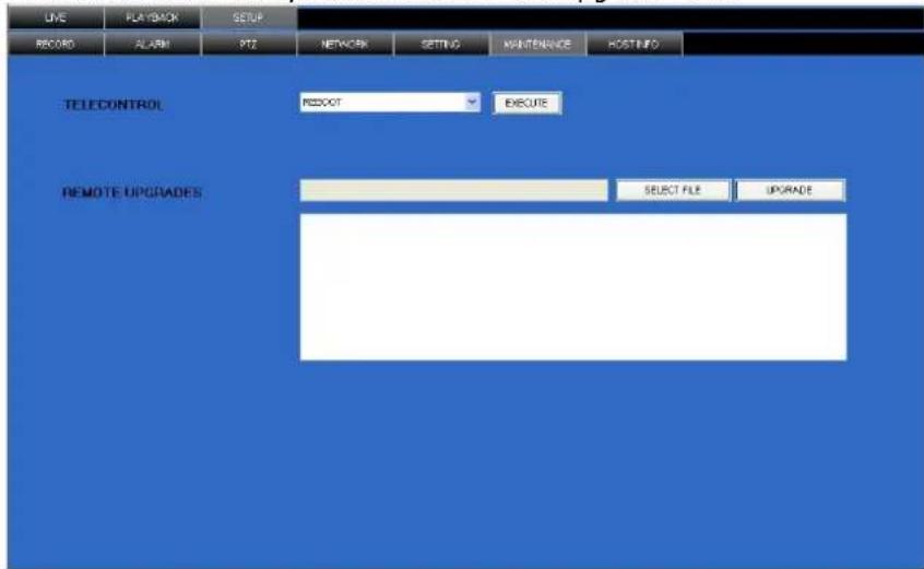
text_image
LINE PLAYBACK SETUP RECORD ALARM 972 NETWORK SETTING MAINTENANCE HOSTINFO TELECONTROL REBOOT EXECUTE REMOTE UPGRADES SELECT FILE UPGRADE8.2.3.7 HOST INFO
Click HOST INFO to access system information interface (see below picture). This interface includes HDD status, remaining recording time, firmware version and MAC Address. This information can not be changed.
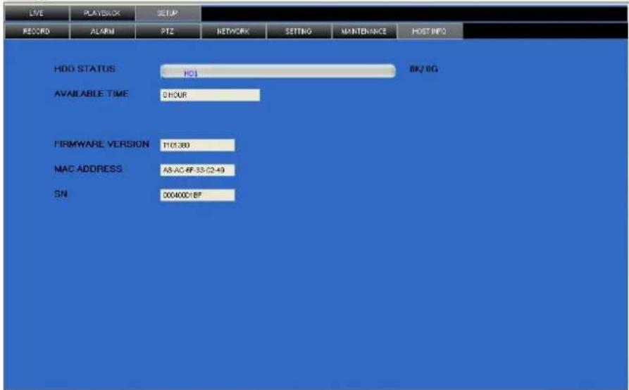
text_image
LIVE PLAYBACK SETUP RECORD ALARM PTZ NETWORK SETTING MANTENANCE HOST INFO HDD STATUS H01 8K/8G AVAILABLE TIME DHOUR FIRMWARE VERSION T01380 MAC ADDRESS A8-AC-BF-33-C2-49 SN 00400C-BF9. FAQ
1. Question: DVR is not working after starting?
Answer:
✨ Check the adaptor input
✨ Check the mains power
✨ Check the power switch (on-off)
✨ Check the main board of the DVR
2. Question: DVR is rebooting automatically or stopped after starting the DVR for several minutes?
Answer:
✨ Instable or low input voltage
✿ Bad track on the hard drive or the cable of the hard drive is bad
✨ Video signal instability
High temperature, too much dust or bad DVR operating environment
✨ The main board is not well-connected with other boards
✨ The hardware of the DVR is defective
3. Question: No output of single channel, multi channel or all channel video?
Answer:
✨ Check all connections of adaptor and cameras
Insert the video source directly into the display device and check whether the problem remains.
◇ Check the brightness of the image and return it to its original default setting
✿ No video input signal or signal too weak
✨ The hardware of DVR is defective
4. Question: DVR cannot record after start-up and the interface is showing "H"
Answer:
✧ Make sure power adaptor output is DC 12V
✨ Make sure HDD is formatted
◇ Check the power and data connection cables of the HDD
✨ The HDD is defective
✨ The SATA port is not working
5. Question: What is meaning of [R] [M] [I] [H] showed in the interface
Answer:
◇ [R] means the channel is recording
✦ [M] means the channel is on motion detection
✦ [I] means the channel is on alarm
✿ [H] means there is either no HDD, the HDD is bad or the HDD is full
6. Question: the DVR is having problems with real-time images, such as bad image, colour or serious brightness distortion...
Answer:
If PAL and NTSC is not correctly selected on the BNC output, the images will be in black and white
✧ DVR is not compatible with attached monitor
✨ The video transmission distance is too far
✿ The setting of DVR colour, brightness and so on are wrong
7. Question: No audio sound when monitoring?
Answer:
◇ Check sound box or speaker functions. Also check possible short circuit.
✿ Audio source may be connected to the video channel. You can click to full-screen to check.
✨ The hardware of DVR is defective
8. Question: No audio sound when playing back?
Answer:
Settings problem: open audio-video item and verify
9. Question: System time is not correct?
Answer:
✿ Wrong setting or user did not click "Edit" to confirm
✨ Battery is not connected properly
✨ Battery is dead. Please change.
10. Question: Why does "Stop recording" via the right mouse button not work, how to stop recording?
Answer:
The "Stop recording" using the right mouse button only works with Manual recording, not during alarm or scheduled recording.
To stop recording, disable alarm or scheduled recording.
11. Question: Motion detection is not working?
Answer:
✿ The setting of the motion detection area is not correct
✨ Sensitivity is too low
12. Question: CD-writer / USB backup error
Answer:
◇ The data exceeds the capacity of the backup device
✨ The backup device is incompatible
✨ The backup device is damaged
13. Question: Remote control cannot work?
Answer:
✨ The address of remote control is not correct
The distance of remote control is too far or the angle is too biased
✨ Remote control batteries ran out
Remote control is damaged or the front panel of DVR is damaged
14. Question: unable to login via Internet?
Answer:
Please check the network to see if it is connected. Check if NET LED is displayed normally on the panel; use ping xxx.xxx.xxx.xxx (DVR IP) to check if the Internet is linked properly.
Make sure to use Windows XP or Vista operating system, also use IE6.0 browser or IE7.0 browser
✧ ActiveX control has been blocked. Manually install ActiveX control again.
✨ Install DX8.1 and upgrade your video card driver
15. Question: There is no picture or picture is not clear when you preview the recording or playback the recording via IE
Answer:
If you access DVR by IE, choose "Wan" in "web environment"
◇ Try "Close windows" by the right mouse button, and try "Open windows" again
16. Question: It displays "other members are setting......" while setting DVR by IE
Answer:
It means someone else is setting the DVR. Please check the DVR configuration interface or exit DVR.
10. Troubleshooting
| Problem | Possible cause | Suggested |
| system is not receiving power system is not powering-up | power adaptor cable loose or unplugged | • check all cable connections |
| not enough input power | • check power LED [6]• connect the DVR straight to the mains (discard power bars, multi-way socket-outlets...)• check mains outlet | |
| remote control not detected by the system | Batteries inside remote control are missing, wrongly inserted or depleted | • check battery polarity• Insert 2 new AAA batteries |
| hard drive not detected by the system | Hard drive cables are loose or badly connectedHard drive missing | • check hard drive connections• install a 3.5” SATA hard drive |
| hard drive is full and DVR is not longer recording | Overwrite is not enabled | • From the mains menu, select HDD - overwrite - enable and click apply |
| mouse not detected by system | Mouse not or badly connected system reset required | • check cabling of the mouse• power off the system (remove power cable!) |
| no image on selected channels | camera cables are loose | • check camera cabling• try connecting the camera to a different channel |
| no sound (image OK) audio cables | bles loose or disconnectedaudio channels disabled in menu volume on external speaker (not incl.) is too low | • check all audio connections• check main menu - record - audio settings• increase output volume |
| system makes noise fan active | • this is normal behaviour | |
| beep at start-up initialisation complete | • this is normal behaviour | |
| e-mail notification doesn’t seem to work | e-mail notification disabled in menuown SMTP information missing | • open main menu - advance - alarm, click e-mail setup and select ‘on’.• enter your SMTP server data correctly |
11. HDD replacement
• To replace the hard disk, unplug the DVR from the mains and disconnect all cabling.
- Release the 6 screws (3 on either side) that hold the cover in place.
- Release the 4 screws that hold the HDD bracket in place.
- Disconnect power supply and data bus.
- Release the screws that hold the HDD is place and remove the HDD.
- Place a new SATA HDD in the bracket and tighten it with 4 screws. The drive must be formatted as FAT32.
- Connect the data bus and power supply and place the mounting bracket back. Tighten the 4 screws.
- Close the cover and reseat the 6 screws.
12. Batt ery
• The remote: control uses 2 batteries type AAA (included)
• To (re)place the batteries, open the battery compartment at the back of the remote control.
- Insert the battery with the right polarity as indicated inside the compartment and close the battery compartment.

WARNING: handle batteries with care, observe warnings on battery casing. Dispose of batteries in accordance with local regulations.
Keep batteries away from children.
13. Tec hnical specifications
DVR
| video format | PAL |
| video compression | H.264 (CIF) |
| video input | 4 channels, composite video signal 1Vpp / 75 ohmsBNC |
| video output | 1x composite video signal 1Vpp / 75 ohms BNC |
| maximum recording rate (PAL) | CIF 32 × 288 pixels @ 100 IPS (PAL) |
| image quality setting | normal - fine - best |
| hard disk storage | built-in SATA type, support 1x HDD (included) |
| recording mode | manual / timer / motion |
| refresh rate | 100 IPS for PAL |
| motion detection area | 13 x 10 grids per channel |
| motion detection sensitivity | 1 averter with 4 sensitivity levels |
| backup device | USB flash drive and network backup |
| PTZ control | RS-485 |
| key lock | yes |
| video loss detection | yes |
| camera title | up to 8 characters |
| video adjustments | contrast / brightness / saturation |
| date display format | MM-DD-YY |
| power supply | 12VDC |
| power consumption | < 30W |
| operating temperature | 10^ 40^ ( 50^ 104^ ) |
| system recovery | system auto recovery after power reconnected |
| dimensions | 200 x 210 x 130mm |
| weight | 2250g |
Camera (4x)
| scanning system | PAL |
| pick-up element | CMOS sensor |
| number of pixels | 628 (H) x 582 (V) - PAL |
| resolution | 380 TV lines |
| min. illumination | 0.2 lux (IR off) |
| IR LEDs | 11 |
| interlace | 2:1 |
| video output | 1.0Vpp composite, 75 ohms |
| gamma correction | 0.45 |
| built-in lens | 6mm |
| lens angle | 39.8° |
| power supply | 12VDC / 300mA (incl.) |
| dimensions | ∅45 x 55mm |
| weight | 290g |
Use this device with original accessories only. Velleman nv cannot be held responsible in the event of damage or injury resulted from (incorrect) use of this device.
For more info concerning this product and the latest version of this user manual, please visit our website www.Perel.eu.
The information in this manual is subject to change without prior notice.
© COPYRIGHT NOTICE
The copyright to this manual is owned by Velleman nv. All worldwide rights reserved.
No part of this manual or may be copied, reproduced, translated or reduced to any electronic medium or otherwise without the prior written consent of the copyright holder.
GEBRUI KERSHANDLEIDING
1. Inleiding
text_image
USER LOGIN DEVICE ID: 000000 (000010) PASSWORD: APPLY EXIT7.2 Schermweergave
text_image
Warning Progress 88% Total:1,Current:1 Back up in process, DO NOT remove the USB driverOpmerking:
text_image
CHANNEL CH1 ON CH2 ON CH3 ON CH4 ON RESOLUTION HIGHEST HIGH NORMAL QUALITY BEST FINE NORMAL AUDIO ENABLE DISABLE REC. MODE POWER UP SCHEDULE REC. SIZE 30Min MASK FILED SETUP Select D1,HD1,CIF for recording quality DEFAULT APPLY EXITtext_image
MASK FIELD MD CHANNEL CH1 CH2 CH3 CH4 SWITCH ON OFF OFF OFF MASK AREA SETUP SETUP SETUP SETUP DEFAULT APPLY EXITtext_image
HDD MANAGEMENT HDD STATUS OK SIZE 250G FREE SPACE 8G AVAILABLE TIME 13Hour OVERWRITE ENABLE HDD FORMAT USB FORMAT Auto delete the oldest record files DEFAULT APPLY EXITtext_image
SYSTEM LANGUAGE ENGLISH 简体中文 ENGLISH Re-starting after the entry into force APPLY EXITtext_image
NAME POSITION COLOR PREVIEW CH1 CH1 TOPLEFT SETUP ON CH2 CH2 TOPLEFT SETUP ON CH3 CH3 TOPLEFT SETUP ON CH4 CH4 TOPLEFT SETUP ON PREVIEW TIME ON RECORD TIME ON DEFAULT APPLY EXITScherminstellingen:
text_image
VID/AUD SETUP CAMARA SYSTEM PAL LOOP TIME 003 (SEC) VOLUME SETUP ADJUST MARGIN APPLY EXITVideo-instellingen:
text_image
ADVANCED SETUP ALARM INFO MD MOBILE MAINTAIN PTZ NETWORK EXIT P-Pan T-Tilt 2-Zoom7.3.5.1 ALARM
Alarm- en e-mailinstellingen.
text_image
ALARM SETUP I/O CHANNEL CH1 CH2 CH3 CH4 I/O ALARM OFF NO OFF NO HDD LOSS ON HDD SPACE OFF VIDEO LOSS OFF ALARM MANAGE OUTPUT 10S BUZZER OS POST REC 1MIN EMAIL SETUP PAMTER ALARM SETUP Buzzer duration time setup DEFAULT APPLY EXITNO (normaal open, when alarm in, close)
OFF (normaal gesloten, when alarm in, open)
text_image
EMAIL SETUP EMAIL ON SSL OFF ON SMTP PORT 00000 SMTP SEND EMAIL SEND PW RECV EMAIL DEFAULT APPLY EXITtext_image
MD CHANNEL CH1 CH2 CH3 Ch4 STATUS ON OFF OFF OFF SENSITIVITY 4 3 2 3 MD AREA SETUP SETUP SETUP SETUP DEFAULT APPLY EXITInstellingen:
natural_image
Grid pattern with white squares on the left and a red square on the right (no text or symbols)text_image
WARNING Processing 50% Upgrading don't pull out thumb drive!text_image
PTZ SETUP CHANNEL CH1 CH2 CH3 CH4 PROTOCOL Pelco-D Pelco-D Pelco-D Pelco-D BAUD RATE 9600 9600 9600 9600 DATA BIT 8 8 8 8 STOP BIT 1 1 1 1 VERIFY ODD ODD ODD ODD ADDRESS 001 001 001 001 DEFAULT APPLY EXITtext_image
NETWORK SETUP TYPE PPPOE MEDIA PORT 09000 WEB PORT 00080 PPPOE NAME PASSWORD DNS 202.096.134.133 DDNS SETTINGS UPNP ○ OPEN ○ CLOSE DEFAULT APPLY EXITtext_image
DDNS SETUP DDNS ON SERVICE 3322 HOST NAME USERNAME PASSWORD DEFAULT APPLY EXITtext_image
Address http://192.168.0.102/ To help protect your security, Internet Explorer stopped this site from installing software on your computer. Click here for options... If your browser do not support to download the ActiveX control, please click here.text_image
PTZ CONTROL ZOOM FOCUS IRIS PRESET 1 SET CALL CLEAN SET CURSE STOP CRUISEUw PTZ-camera bedienen:
text_image
DyOcx Other user Downloading now OK8.2.3.2 ALARM SETTING
12. Vraag: Fout cd-writer/ USB-back-up?
Antwoord:
text_image
USER LOGIN DEVICE ID: 000000 (000010) PASSWORD: APPLY EXITtext_image
Warning Progress 88% Total:1,Current:1 Back up in process, DO NOT remove the USB driverRemarque :
text_image
CHANNEL CH1 ON CH2 ON CH3 ON CH4 ON RESOLUTION HIGHEST HIGH NORMAL QUALITY BEST PINE NORMAL AUDIO ENABLE DISABLE REC. MODE POWER UP SCHEDULE REC. SIZE 30Min MASK FILED SETUP Select D1,HD1,CIF for recording quality DEFAULT APPLY EXITIllustration 2.4.2.3.1 RECORD
Configuration des options :
text_image
CHANNEL ALL 00 06 12 18 23 SUN MON TUE WED THU FRI SAT ✓ ALARM GENERAL MANUAL RECORD COPY SUN TO ALL COPY DEFAULT SAVE EXITIllustration 2.4.2.3.1 SCHEDULE
text_image
MASK FIELD MD CHANNEL CH1 CH2 CH3 CH4 SWITCH ON OFF OFF OFF MASK AREA SETUP SETUP SETUP SETUP DEFAULT APPLY EXITtext_image
HDD MANAGEMENT HDD STATUS OK SIZE 250G FREE SPACE 8G AVAILABLE TIME 13Hour OVERWRITE ENABLE HDD FORMAT USB FORMAT Auto delete the oldest record files DEFAULT APPLY EXITtext_image
SYSTEM LANGUAGE SYSTEM LANGUAGE ENGLISH 简体中文 ENGLISH Re-starting after the entry into force APPLY EXITtext_image
DISPLAY SETUP NAME POSITION COLOR PREVIEW CH1 CH1 TOPLEFT SETUP ON CH2 CH2 TOPLEFT SETUP ON CH3 CH3 TOPLEFT SETUP ON CH4 CH4 TOPLEFT SETUP ON PREVIEW TIME ON RECORD TIME ON DEFAULT APPLY EXITtext_image
VID/AUD SETUP CAMARA SYSTEM PAL LOOP TIME 003 (SEC) VOLUME SETUP ADJUST MARGIN APPLY EXITtext_image
ADVANCED SETUP ALARM INFO MD MOBILE MAINTAIN PTZ NETWORK EXIT P-Pan T-Tilt Z-Zoom7.3.5.1 ALARM
text_image
ALARM SETUP I/O CHANNEL CH1 CH2 CH3 CH4 I/O ALARM OFF NO OFF NO HDD LOSS ON HDD SPACE OFF VIDEO LOSS OFF ALARM MANAGE OUTPUT 10S BUZZER OS POST REC 1MIN EMAIL SETUP PAMTER ALARM SETUP Buzzer duration time setup DEFAULT APPLY EXITtext_image
EMAIL SETUP EMAIL ON SSL OFF ON SMTP PORT 00000 SMTP SEND EMAIL SEND PW RECV EMAIL DEFAULT APPLY EXITConfiguration :
text_image
MD CHANNEL CH1 CH2 CH3 Ch4 STATUS ON OFF OFF OFF SENSITIVITY 4 3 2 3 MD AREA SETUP SETUP SETUP SETUP DEFAULT APPLY EXITConfiguration :
natural_image
Grid pattern with white squares on the left and a small yellow square on the right (no text or symbols)text_image
WARNING Processing 50% Upgrading don't pull out thumb drive!text_image
PTZ SETUP CHANNEL CH1 CH2 CH3 CH4 PROTOCOL Pelco-D Pelco-D Pelco-D Pelco-D BAUD RATE 9600 9600 9600 9600 DATA BIT 8 8 8 8 STOP BIT 1 1 1 1 VERIFY ODD ODD ODD ODD ADDRESS 001 001 001 001 DEFAULT APPLY EXITConfiguration :
text_image
TYPE PPPOE MEDIA PORT 09000 WEB PORT 00080 PPPOE NAME PASSWORD DNS 202.096.134.133 DDNS SETTINGS UPNP ○ OPEN ○ CLOSE DEFAULT APPLY EXITRemarque : Se registrer You must register DDNS service prior to configuring DDNS settings.
Visiter le site https://www.dyndns.com/.

text_image
DDNS SETUP DDNS ON SERVICE 3322 HOST NAME USERNAME PASSWORD DEFAULT APPLY EXITtext_image
Address http://192.168.0.102/ To help protect your security, Internet Explorer stopped this site from installing software on your computer. Click here for options... If your browser do not support to download the ActiveX control, please click here.text_image
PTZ CONTROL ZOOM FOCUS IRIS PREFSET 1 SET CALL CLEAN SET CURSE STOP CRUISEtext_image
DvrOx Other user Downloading now OKtext_image
USER LOGIN DEVICE ID: 000000 (000010) PASSWORD: APPLY EXITtext_image
Warning Progress 88% Total:1,Current:1 Back up in process, DO NOT remove the USB driverNota:
text_image
RECORD CHANNEL CH1 ON CH2 ON CH3 ON CH4 ON RESOLUTION HIGHEST HIGH NORMAL QUALITY BEST FINE NORMAL AUDIO ENABLE DISABLE REC. MODE POWER UP SCHEDULE REC. SIZE 30Min MASK FILED SETUP Select D1.HDI.CIF for recording quality DEFAULT APPLY EXITtext_image
MASK FIELD MD CHANNEL CH1 CH2 CH3 CH4 SWITCH ON OFF OFF OFF MASK AREA SETUP SETUP SETUP SETUP DEFAULT APPLY EXITtext_image
HDD MANAGEMENT HDD STATUS OK SIZE 250G FREE SPACE 8G AVAILABLE TIME 13Hour OVERWRITE ENABLE HDD FORMAT USB FORMAT Auto delete the oldest record files DEFAULT APPLY EXITtext_image
SYSTEM LANGUAGE SYSTEM LANGUAGE ENGLISH 简体中文 ENGLISH Re-starting after the entry into force APPLY EXITtext_image
NAME POSITION COLOR PREVIEW CH1 CH1 TOPLEFT SETUP ON CH2 CH2 TOPLEFT SETUP ON CH3 CH3 TOPLEFT SETUP ON CH4 CH4 TOPLEFT SETUP ON PREVIEW TIME ON RECORD TIME ON DEFAULT APPLY EXITConfigurar:
text_image
VID/AUD SETUP CAMARA SYSTEM PAL LOOP TIME 003 (SEC) VOLUME SETUP ADJUST MARGIN APPLY EXITtext_image
ADVANCED SETUP ALARM INFO MD MOBILE MAINTAIN PTZ NETWORK EXIT P-Pan T-Tilt Z-Zoom7.3.5.1 ALARM
text_image
ALARM SETUP I/O CHANNEL CH1 CH2 CH3 CH4 I/O ALARM OFF NO OFF NO HDD LOSS ON HDD SPACE OFF VIDEO LOSS OFF ALARM MANAGE OUTPUT 10S BUZZER OS POST REC 1MIN EMAIL SETUP PAMTER ALARM SETUP Buzzer duration time setup DEFAULT APPLY EXITtext_image
EMAIL SETUP EMAIL ON SSL OFF ON SMTP PORT 00000 SMTP SEND EMAIL SEND PW RECV EMAIL DEFAULT APPLY EXITConfiguración:
text_image
MOTION DETECT MD CHANNEL CH1 CH2 CH3 Ch4 STATUS ON OFF OFF OFF SENSITIVITY 4 3 2 3 MD AREA SETUP SETUP SETUP SETUP DEFAULT APPLY EXITConfiguración:
natural_image
Grid pattern with white squares on the left and a small yellow square on the right (no text or symbols)text_image
WARNING Processing 50% Upgrading, don't pull out thumb drive!text_image
PTZ SETUP CHANNEL CH1 CH2 CH3 CH4 PROTOCOL Pelco-D Pelco-D Pelco-D Pelco-D BAUD RATE 9600 9600 9600 9600 DATA BIT 8 8 8 8 STOP BIT 1 1 1 1 VERIFY ODD ODD ODD ODD ADDRESS 001 001 001 001 DEFAULT APPLY EXITConfiguración:
text_image
TYPE PPPOE MEDIA PORT 09000 WEB PORT 00080 PPPOE NAME PASSWORD DNS 202.096.134.133 DDNS SETTINGS UPNP OPEN CLOSE DEFAULT APPLY EXITtext_image
WAN Connection Type: PPPoE QoS Engine: Active Cable Status: Connected Network Status: Established Connection Up Time: 0 Days, 0:15:01 Connect Disconnect MAC Address: 00:1E:58:2E:43:AA Authentication & Security: PAP IP Address: 209.195.113.46 Subnet Mask: 255.255.255.255 Default Gateway: 192.168.200.1 Primary DNS Server: 216.58.97.21 Secondary DNS Server: 216.58.97.20DDNS
text_image
DDNS ON SERVICE 3322 HOST NAME USERNAME PASSWORD DEFAULT APPLY EXITtext_image
Address http://192.168.0.102/ To help protect your security. Internet Explorer stopped this site from installing software on your computer. Click here for options... If your browser do not support to download the ActiveX control, please click here.text_image
PTZ CONTROL ZOOM FOCUS IRIS PRESET 1 SET CALL CLEAN SET CURISE STOP CRUISEtext_image
DvrOcx Other user Downloading now OKtext_image
USER LOGIN DEVICE ID: 000000 (000010) PASSWORD: APPLY EXITtext_image
Warning Progress 88% Total:1,Current:1 Back up in process, DO NOT remove the USB driverBemerkung:
text_image
RECORD CHANNEL CH1 ON CH2 ON CH3 ON CH4 ON RESOLUTION HIGHEST HIGH NORMAL QUALITY BEST FINE NORMAL AUDIO ENABLE DISABLE REC. MODE POWER UP SCHEDULE REC. SIZE 30Min MASK FILED SETUP Select D1,HD1,CIF for recording quality DEFAULT APPLY EXITtext_image
MASK FIELD MD CHANNEL CH1 CH2 CH3 CH4 SWITCH ON OFF OFF OFF MASK AREA SETUP SETUP SETUP SETUP DEFAULT APPLY EXITtext_image
HDD MANAGEMENT HDD STATUS OK SIZE 250G FREE SPACE 8G AVAILABLE TIME 13Hour OVERWRITE ENABLE HDD FORMAT USB FORMAT Auto delete the oldest record files DEFAULT APPLY EXITtext_image
SYSTEM LANGUAGE SYSTEM LANGUAGE ENGLISH 简体中文 ENGLISH Re-starting after the entry into force APPLY EXITtext_image
DISPLAY SETUP NAME POSITION COLOR PREVIEW CH1 CH1 TOPLEFT SETUP ON CH2 CH2 TOPLEFT SETUP ON CH3 CH3 TOPLEFT SETUP ON CH4 CH4 TOPLEFT SETUP ON PREVIEW TIME ON RECORD TIME ON DEFAULT APPLY EXITtext_image
VID/AUD SETUP CAMARA SYSTEM PAL LOOP TIME 003 (SEC) VOLUME SETUP ADJUST MARGIN APPLY EXITCCTVSET10
text_image
ALARM INFO MD MOBILE MAINTAIN PTZ NETWORK EXIT P-Pan T-tilt Z-Zoom7.3.5.1 ALARM
text_image
EMAIL SETUP EMAIL ON SSL OFF ON SMTP PORT 00000 SMTP SEND EMAIL SEND PW RECV EMAIL DEFAULT APPLY EXITtext_image
MD CHANNEL CH1 CH2 CH3 Ch4 STATUS ON OFF OFF OFF SENSITIVITY 4 3 2 3 MD AREA SETUP SETUP SETUP SETUP DEFAULT APPLY EXITEinstellungen:
natural_image
Grid pattern with red and white squares, one highlighted by a yellow square (no text or symbols)text_image
WARNING Processing 50% Upgrading, don't pull out thumb drive!text_image
PTZ SETUP CHANNEL CH1 CH2 CH3 CH4 PROTOCOL Pelco-D Pelco-D Pelco-D Pelco-D BAUD RATE 9600 9600 9600 9600 DATA BIT 8 8 8 8 STOP BIT 1 1 1 1 VERIFY ODD ODD ODD ODD ADDRESS 001 001 001 001 DEFAULT APPLY EXITtext_image
NETWORK SETUP TYPE PPPOE MEDIA PORT 09000 WEB PORT 00080 PPPOE NAME PASSWORD DNS 202.096.134.133 DDNS SETTINGS UPNP ○ OPEN ○ CLOSE DEFAULT APPLY EXITtext_image
DDNS SETUP DDNS ON SERVICE 3322 HOST NAME USERNAME PASSWORD DEFAULT APPLY EXITtext_image
Address http://192.168.0.102/ To help protect your security, Internet Explorer stopped this site from installing software on your computer. Click here for options... If your browser do not support to download the ActiveX control, please click here.text_image
PTZ CONTROL 200M FOCUS IRIS PRESET 1 SET CALL CLEAN SET CURISE STOP CRUISEtext_image
DvrOcx Other user Downloading now OK8.2.3.2 ALARM SETTING
text_image
USER LOGIN DEVICE ID: 000000 (000010) PASSWORD: APPLY EXITtext_image
Warning Progress 88% Total:1,Current:1 Back up in process, DO NOT remove the USB driverNota:
text_image
CHANNEL CH1 ON CH2 ON CH3 ON CH4 ON RESOLUTION HIGHEST HIGH NORMAL QUALITY BEST FINE NORMAL AUDIO ENABLE DISABLE REC. MODE POWER UP SCHEDULE REC. SIZE 30Min MASK FILED SETUP Select D1.HD1.CIF for recording quality DEFAULT APPLY EXIT1) Em CHANNEL, active/desactive o som fazendo clic ON/ OFF no menu do canal.
2) Em RESOLUTION, seleccione HIGHEST, HIGH ou NORMAL (resolução de D1, HD1, CIF). Nota: PAL: D1 @ 6 IPS, HD1 @ 12 IPS, CIF @ 24 IPS/NTSC: D1 @ 7 IPS, HD1 @ 15 IPS, CIF @ 30 IPS.
3) Em QUALITY, seleccione BEST, FINE ou NORMAL. CIF: 384 kb/s y 512 kb/s y 768 kb/s HD1: 512 kb/s y 768 kb/s y 1024 kb/s D1: 512 kb/s y 768 kb/s y 1024 kb/s
6) Em REC. SIZE, seleccione 15MIN, 30MIN, 45MIN ou 60MIN.
text_image
CHANNEL ALL 00 06 12 18 23 SUN MON TUE WED THU FRI SAT ✓ ALARM GENERAL MANUAL RECORD COPY SUN TO ALL COPY DEFAULT SAVE EXITtext_image
MASK FIELD MD CHANNEL CH1 CH2 CH3 CH4 SWITCH ON OFF OFF OFF MASK AREA SETUP SETUP SETUP SETUP DEFAULT APPLY EXITtext_image
HDD MANAGEMENT HDD STATUS OK SIZE 250G FREE SPACE 8G AVAILABLE TIME 13Hour OVERWRITE ENABLE HDD FORMAT USB FORMAT Auto delete the oldest record files DEFAULT APPLY EXITtext_image
SYSTEM LANGUAGE ENGLISH 简体中文 ENGLISH Re-starting after the entry into force APPLY EXITtext_image
DISPLAY SETUP NAME POSITION COLOR PREVIEW CH1 CH1 TOPLEFT SETUP ON CH2 CH2 TOPLEFT SETUP ON CH3 CH3 TOPLEFT SETUP ON CH4 CH4 TOPLEFT SETUP ON PREVIEW TIME ON RECORD TIME ON DEFAULT APPLY EXITConfigurar:
text_image
VID/AUD SETUP CAMARA SYSTEM PAL LOOP TIME 003 (SEC) VOLUME SETUP ADJUST MARGIN APPLY EXITtext_image
ADVANCED SETUP ALARM INFO MD MOBILE MAINTAIN PTZ NETWORK EXIT P-Pan T-Tilt Z-Zoom7.3.5.1 ALARM
text_image
ALARM SETUP I/O CHANNEL CH1 CH2 CH3 CH4 I/O ALARM OFF NO OFF NO HDD LOSS ON HDD SPACE OFF VIDEO LOSS OFF ALARM MANAGE OUTPUT 10S BUZZER OS POST REC 1MIN EMAIL SETUP PAMTER ALARM SETUP Buzzer duration time setup DEFAULT APPLY EXITtext_image
EMAIL SETUP EMAIL ON SSL OFF ON SMTP PORT 00000 SMTP SEND EMAIL SEND PW RECV EMAIL DEFAULT APPLY EXITConfiguração:
-
Em EMAIL, seleccione ON.
-
Em SSL, seleccione OFF.
text_image
MOTION DETECT MD CHANNEL CH1 CH2 CH3 Ch4 STATUS ON OFF OFF OFF SENSITIVITY 4 3 2 3 MD AREA SETUP SETUP SETUP DEFAULT APPLY EXITConfiguração:
natural_image
Grid pattern with a small yellow square overlay on the right side (no text or symbols)text_image
WARNING Processing 50% Upgrading don't pull out thumb drive!text_image
PTZ SETUP CHANNEL CH1 CH2 CH3 CH4 PROTOCOL Pelco-D Pelco-D Pelco-D Pelco-D BAUD RATE 9600 9600 9600 9600 DATA BIT 8 8 8 8 STOP BIT 1 1 1 1 VERIFY ODD ODD ODD ODD ADDRESS 001 001 001 001 DEFAULT APPLY EXITConfiguração:
text_image
TYPE PPPOE MEDIA PORT 09000 WEB PORT 00080 PPPOE NAME PASSWORD DNS 202.096.134.133 DDNS SETTINGS UPNP OPEN CLOSE DEFAULT APPLY EXITtext_image
DDNS SETUP DDNS ON SERVICE 3322 HOST NAME USERNAME PASSWORD DEFAULT APPLY EXITtext_image
Address http://192.168.0.102/ To help protect your security. Internet Explorer stopped this site from installing software on your computer. Click here for options... If your browser do not support to download the ActiveX control, please click here.text_image
PTZ CONTROL ZOOM FOCUS IRIS PRESET 1 SET CALL CLEAN SET CURSE STOP CRUISEControlar a câmara: