CCTVSET2 - Surveillance Camera Perel - Free user manual and instructions
Find the device manual for free CCTVSET2 Perel in PDF.

User questions about CCTVSET2 Perel
0 question about this device. Answer the ones you know or ask your own.
Ask a new question about this device
Download the instructions for your Surveillance Camera in PDF format for free! Find your manual CCTVSET2 - Perel and take your electronic device back in hand. On this page are published all the documents necessary for the use of your device. CCTVSET2 by Perel.
USER MANUAL CCTVSET2 Perel
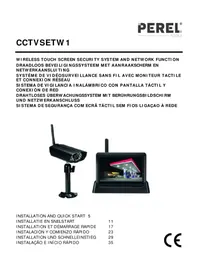
VIDEO SECURITY SET: DVR + 4 CAMERAS + ACCESSORIES + 500 GB HARD DISK
STANDAARD VIDEOBEWAKINGSSET: DVR + 4 CAMERA'S + ACCESSOIRES + 500 GB HD
SET DE BASE DE SÉCURITÉ VIDÉO: DVR + 4 CAMÉRAS + ACCESSOIRES + DISQUE DUR DE 500 GO
JUEGO DE VIGILANCIA ECONÓMICO: VIDEOGRABADORA DIGITAL + 4 CÁMARAS + ACCESORIOS + DISCO DURO DE 500 GB
natural_image
Black H.264 Network DVR security camera with four mounted cameras (no visible text or symbols on the device body)USER MANUAL 3
GEBRUIKERSHANDLEIDING 29
MODE D'EMPLOI 55
MANUAL DEL USUARIO 81
To all residents of the European Union
Important environmental information about this product

This symbol on the device or the package indicates that disposal of the device after its lifecycle could harm the environment. Do not dispose of the unit (or batteries) as unsorted municipal waste; it should be taken to a specialized company for recycling. This device should be returned to your distributor or to a local recycling service. Respect the local environmental rules.

If in doubt, contact your local waste disposal authorities.
Thank you for choosing Perel! Please read the manual thoroughly before bringing this device into service. If the device was damaged in transit, do not install or use it and contact your dealer.
2. Safety Instructions
 | Keep the device away from children and unauthorised users. |
 | Risk of electroshock when opening the cover. Touching live wires can cause life-threatening electroshocks. |
 | Always disconnect mains power when the device is not in use or when servicing or maintenance activities are performed. Handle the power cord by the plug only. |
3. General Guidelines
Refer to the Velleman® Service and Quality Warranty on the last pages of this manual.
 | Keep this device away from dust. |
 | Keep this device away from extreme heat.Make sure the ventilation openings are clear at all times. |
 | Protect this device from shocks and abuse. Avoid brute force when operating the device. |
- Familiarise yourself with the functions of the device before actually using it.
- All modifications of the device are forbidden for safety reasons.
- Only use the device for its intended purpose. Using the device in an unauthorised way will void the warranty.
- Damage caused by disregard of certain guidelines in this manual is not covered by the warranty and the dealer will not accept responsibility for any ensuing defects or problems.
- Do not use this product to violate privacy laws or perform other illegal activities.
- Keep this manual for future reference.
4. Features
This economic camera security set is an easy-to use security system for home surveillance. This set contains 4 CMOS cameras with 600 TV lines. An IR-cut filter will filter the IR light, so it cannot distort the colour image during daytime. The digital video recorder records the video images on the built-in 500 GB hard disk via motion detection, timer or manual recording. Plug-and-play remote surveillance via smartphone apps.
- contents:
- 1 x DVR with built-in SATA connection
- 4 x CMOS bullet camera with IR LEDs
- 4 x 18 m camera cable
- USB mouse and accessories
○ 1 x 12 V PSU - hard disk: 500 GB
CCTVSET2
- plug-and-play remote surveillance via smartphone apps
○ Android ®: ATVCloud
○ Apple ^ (iPhone ^ , iPod ^ and iPad ^ ): ATVCloud
- optional (not incl.):
o VGA & DVI monitor: MONSCA5N
- router: EM4544, EM4571
5. Overview
Refer to the illustrations on page 2 of this manual.
Front Panel
| 1 | IR sensor (not used) |
| 2 | power LED |
| 3 | recording LED |
Rear Panel
| 1 | video input |
| 2 | video output |
| 3 | audio output |
| 4 | VGA output |
| 5 | HDMI® connection |
| 6 | audio input |
| 7 | USB connections |
| 8 | RS-485 connection |
| 9 | power input |
| 10 | RJ-45 connection |
6. Installation
6.1 HDD Installation
The digital video recorder (DVR) comes fully installed with hard disk drive (HDD). Just connect the DVR to your monitor (not included) and router (not included). Also, connect the DVR to the mains.
6.2 Icon Description
| recording | |
| client-end linking to channel | |
| channel with set alarm, alarm not triggered | |
| alarm is triggered | |
| voice monitoring closed | |
| voice monitoring open |
7. Fast Operation
7.1 Login
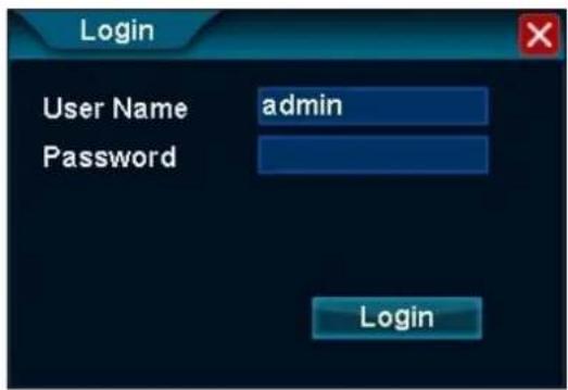
After starting up the DVR, a pop-up window appears. Login to the DVR.
text_image
Login User Name admin Password LoginCCTVSET2
- Enter the default user name [admin] in the User Name field.
- You do not need to enter a password in the Password field.
- Left-click Login to finish the login operation.
REMARK
- The mouse will be locked for 10 seconds after three failed login attempts. Enter the correct login user name as soon as the mouse unlocks.
7.2 Menu Operation
After logging in, the main screen appears. Move your mouse cursor to lower part of the screen to display the menu bar.

text_image
Screenshot of a software toolbar with icons for tools, applications, and functionsHover over the icons to discover the menu name. From left to right: System Setup, View Layout, Sequence, Zoom, Video Adjust, PTZ, Snapshot, Photos, Record Setup, Playback, Quit.
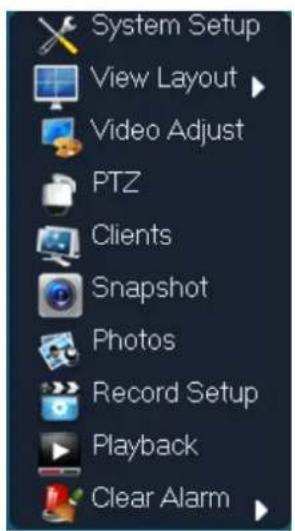
You can also right-click anywhere in the screen to display the menu below:
text_image
System Setup View Layout Video Adjust PTZ Clients Snapshot Photos Record Setup Playback Clear AlarmLeft-click anywhere in the screen (not on an icon) to make the menu disappear.
7.2.1 View Layout

flowchart
graph LR
    A["View Layout"] --> B["View 1"]
    A --> C["View 4"]
Adjust the screen to one-screen (View 1) or four-screen mode (View 4).
7.2.2 Sequence

The sequence function automatically switches through all four channels in a continuous loop. The switching speed can be set as follows:
CCTVSET2
- Left-click the Sequence icon to enter the function.
- Left-click in the field. Enter the interval in seconds using the numeric keypad and confirm with OK.
- Left-click OK to confirm and to activate the function.

- Left-click the Stop Sequence icon to disable the sequence function.

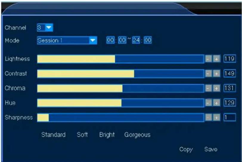
7.2.3 Video Adjust

The video adjustment menu allows detailed image adjustments for each channel with custom modes (sessions 1, 2 and 3). The custom modes can be used as pre-set modes for e.g. day or night recording. Set as follows:
- Left-click the Video Adjust icon to enter the function.
- Select the channel for your setup.
- Select the session for your channel, e.g. use session 1 for your day settings, session 2 for your night settings and session 3 for other settings. Also, identify your session by setting the session time in the time fields.

- Manually adjust each item, either by clicking in the bar or by clicking [+] or [-]. You can also select factory settings (Standard - Soft - Bright - Gorgeous) at the bottom of the window.
- Left-click Save to save your settings.
- Repeat for all channels and sessions.
bar
| Channel | Standard | Soft | Bright | Gorgeous | | --------- | -------- | ---- | ------ | -------- | | Lightness | - | + | - | 119 | | Contrast | - | + | - | 149 | | Chroma | - | + | - | 131 | | Hue | - | + | - | 129 | | Sharpness | - | + | - | 1 |7.2.5 Clients

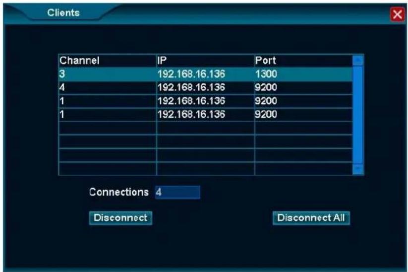
The Clients function lists all remote hosts connected to the DVR.
text_image
Clients Channel IP Port 3 192.168.16.136 1300 4 192.168.16.136 9200 1 192.168.16.136 9200 1 192.168.16.136 9200 Connections 4 Disconnect Disconnect All- To disconnect a host, left-click the remote host to select.
- Left-click Disconnect.
- Left-click Disconnect All to disconnect all hosts simultaneously.
7.2.6 Snapshot

The Snapshot function allows you to take screenshots of the selected channel. Proceed as follows:
- Left-click the Snapshot icon to enter the function. You will see the mouse cursor change into a camera.
- Move into the screen and left-click once. The screenshot will be automatically saved onto the HDD.
- Right-click once to exit the function.
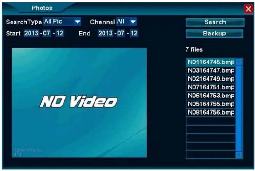
7.2.7 Photos

The Photos function allows you to upload the screenshots saved onto the HDD and, if desired, save them onto a USB stick (not included).
Searching a Saved Snapshot
- Left-click the Photos icon to enter the function.
- Enter all the necessary info in the appropriate fields. Note that snapshots older than one month cannot be retrieved.
- Left-click Search to search your snapshots. The snapshots will be listed on the right of the window.
- Left-click on the desired file to view your snapshot.
text_image
Photos SearchType All Pic Channel All Start 2013 -07 - 12 End 2013 -07 - 12 NO Video Search Backup 7 files N01164745.bmp N03164747.bmp N02164749.bmp N07164751.bmp N06164753.bmp N05164755.bmp N08164756.bmpTransferring a Saved Snapshot onto a USB Stick
- Insert your USB stick into one of the USB ports at the back of the DVR.
- Search and select your snapshot as described under 7.2.7 Searching a Saved Snapshot above.
- Left-click Backup and save the snapshot on your USB stick.
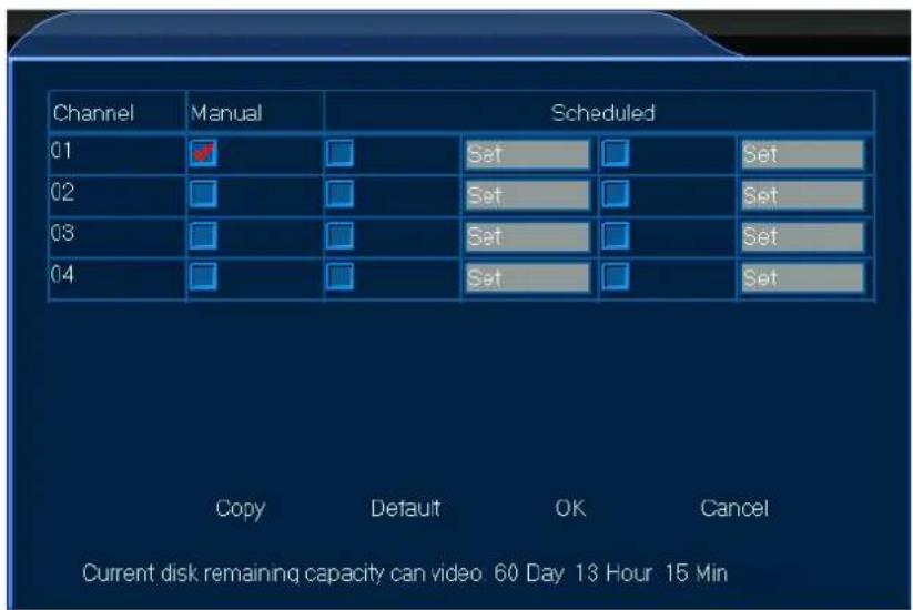
7.2.8 Record Setup

Record Setup
The Record Setup function allows you to record videos, either manually or programmed.
Manual Recording
- Left-click the Record Setup icon to enter the function.
text_image
Channel Manual Scheduled 01 Set Set 02 Set Set 03 Set Set 04 Set Set Copy Default OK Cancel Current disk remaining capacity can video 60 Day 13 Hour 15 Min- Select your channel and check off the manual option.
- Left-click OK to start the recording.
- Enter the function, uncheck the manual option and left-click OK to abort the recording.
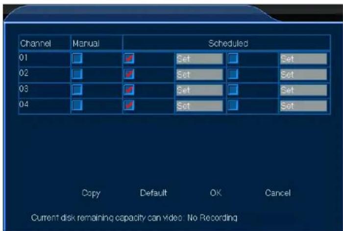
Scheduled Recording
- Left-click the Record Setup icon to enter the function.
text_image
Channel Manual Scheduled 01 Set Set 02 Set Set 03 Set Set 04 Set Copy Default OK Cancel Current disk remaining capacity can video: No Recording- Select your channel and check off the scheduled option.
- Left-click Set for the selected channel to open the programme window.
- Enter the starting and ending times for your recording. Left-click OK to confirm the schedule.
- Left-click OK to confirm the recording. Recording will start and end at the programmed time.
REMARK
- When recording, the recording icon will appear in the lower left corner of the selected channel.

7.2.9 Playback

The Playback function allows you to play and view your recorded videos, as well as save them onto a USB stick.
Recording Playback
- Left-click the Playback icon to enter the function.
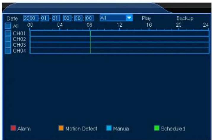
text_image
Date 2000 01 01 00 00 00 All Play Backup All 00 04 08 12 16 20 24 CH01 CH02 CH03 CH04 Alarm Motion Detect Manual ScheduledCCTVSET2
- Select your channel and enter all necessary parameters to fine-tune your recording selection.
- Left-click Play to enter the Playback window (see The Playback Window below).
The Playback Window
The Playback Window allows several playback functions for your recorded video.
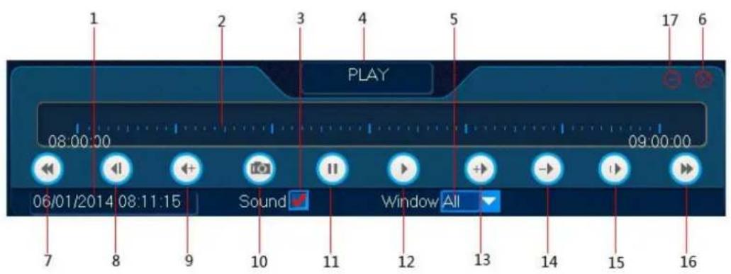
text_image
1 2 3 4 5 PLAY 08:00:00 09:00:00 06/01/2014 08:11:15 Sound Window All 7 8 9 10 11 12 13 14 15 16| 1 | PLAYBACK TIME: current playback time |
| 2 | PROGRESS BAR: progress of the current file |
| 3 | SOUND: enable/disable the sound function |
| 4 | FUNCTION: selected function in the playback window |
| 5 | WINDOW: channel selection |
| 6 | EXIT: exit the playback window |
| 7 | PRIOR HOUR: go back one hour |
| 8 | BACKSTEP: pause and go back two seconds |
| 9 | BACKFAST: play backwards at speed x 4, 8 or 16 |
| 10 | SNAP: take a snapshot |
| 11 | PAUSE: pause the video |
| 12 | PLAY: play the video |
| 13 | FAST: play forward at speed x 2, 4, 8 or 16 |
| 14 | SLOW: play forward at speed x 1/2, 1/4, 1/8 or 1/16 |
| 15 | STEP: jump one frame at the time |
| 16 | NEXT HOUR: go forward one hour |
| 17 | MINIMIZES: minimize the playback window |
Saving Your Recording
- Left-click Backup to enter the function.
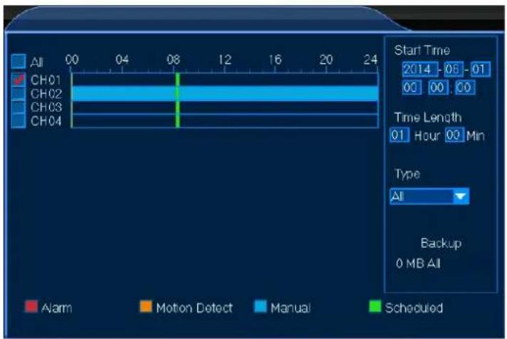
text_image
All CH01 CH02 CH03 CH04 00 04 08 12 16 20 24 Start Time 2014 - 06 01 00 00 00 Time Length 01 Hour 00 Min Type All Backup 0 MB All Alarm Motion Detect Manual ScheduledCCTVSET2
- Select your channel and enter all necessary parameters to fine-tune your recording selection.
- Left-click Backup to save your recording.
REMARK
- Make sure to have your USB stick connected to the DVR.
7.2.10 Clear Alarm

flowchart
graph LR
    A["Clear Alarm"] --> B["Current Clear All"]
The Clear Alarm function allows you to clear the alarm settings for one selected channel or all channels. Proceed as follows:
- Left-click the appropriate window to select your channel.
- Left-click the Photos icon to enter the function.
- Left-click Current to clear the alarm settings for the selected channel or Clear All to clear all alarm settings.
REMARK
• Refer to chapter 8.4 Alarm below to set up the alarm function.
7.2.11 Quit

The Quit function allows you to log out, shut down or restart the DVR.

text_image
Quit Logout Shutdown Restart8. System Setup
The System Setup menu contains all necessary functions to set up your DVR system in detail.

- Left-click the System Setup icon to enter the menu.
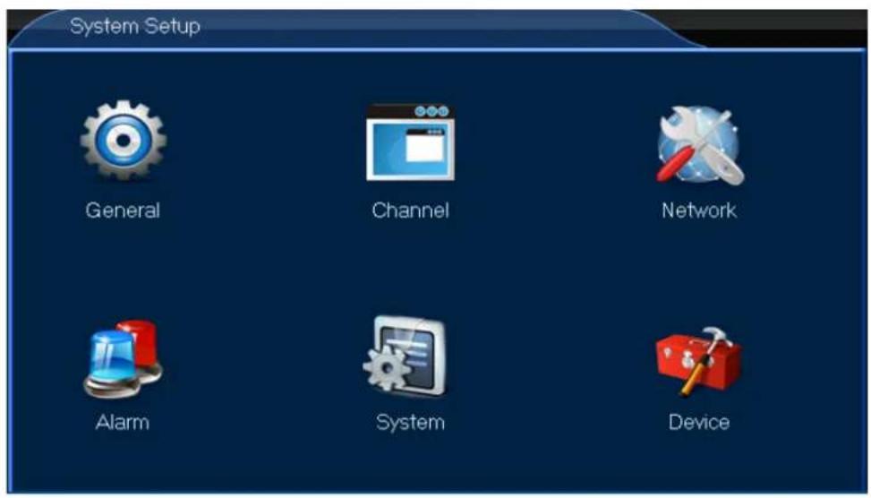
text_image
System Setup General Channel Network Alarm System Device8.1 General

- Left-click the General icon to enter the menu.
text_image
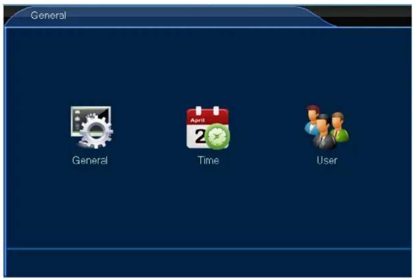
General General Time User8.1.1 General

The General menu allows you to adjust all general settings. Proceed as follows:
- Left-click the General icon to enter the menu.
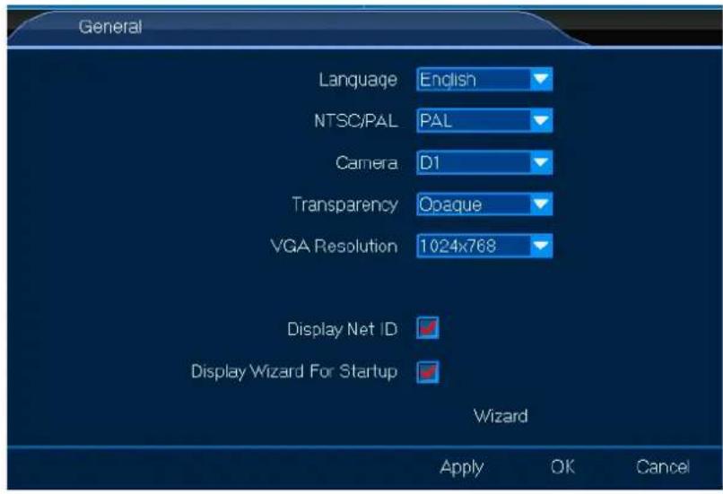
text_image
General Language English NTSC/PAL PAL Camera D1 Transparency Opaque VGA Resolution 1024x768 Display Net ID ✓ Display Wizard For Startup ✓ Wizard Apply OK Cancel- Set up as desired.
- Left-click OK to confirm.
8.1.2 Time

The Time allows you to adjust all time settings. Proceed as follows:
- Left-click the Time icon to enter the menu.
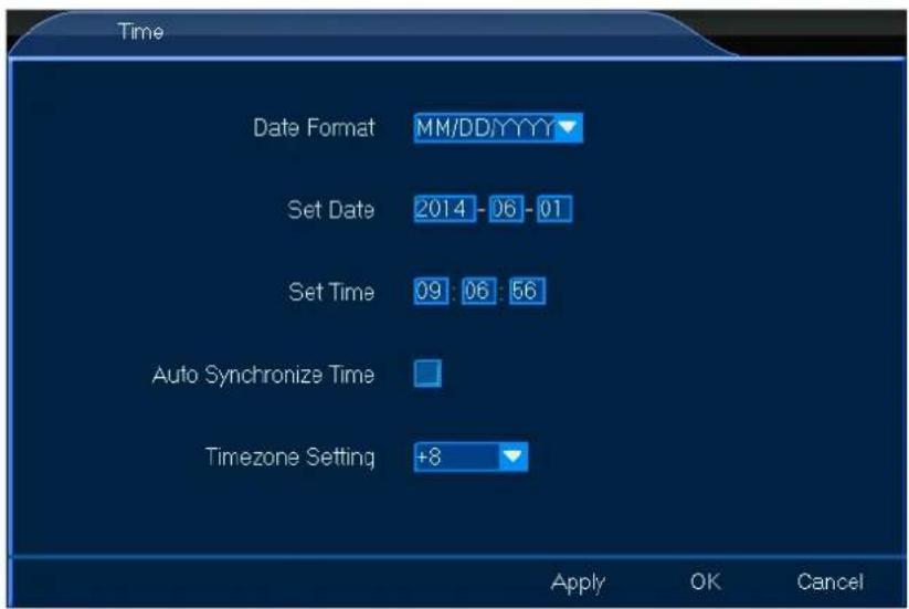
text_image
Time Date Format MM/DD/YYYY▼ Set Date 2014 - 06 - 01 Set Time 09 : 06 : 56 Auto Synchronize Time Timezone Setting +8 ▼ Apply OK Cancel- Set up as desired.
- Left-click OK to confirm.
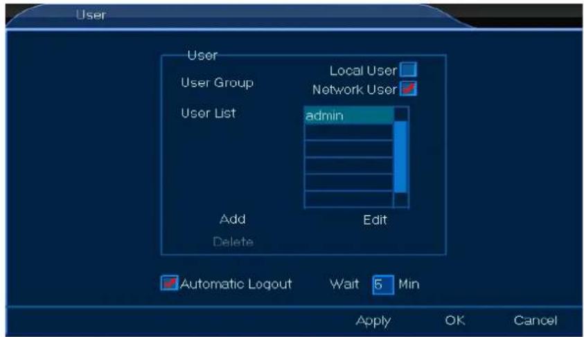
8.1.3 User

The User menu allows you to adjust all user settings, either a local or network user. Proceed as follows:
Local User
- Left-click the User icon to enter the menu.
- Check off the Local User box and left-click Add or Edit.

text_image
User User User Group Local User Network User User List admin Add Edit Delete Automatic Logout Wait 5 Min Apply OK Cancel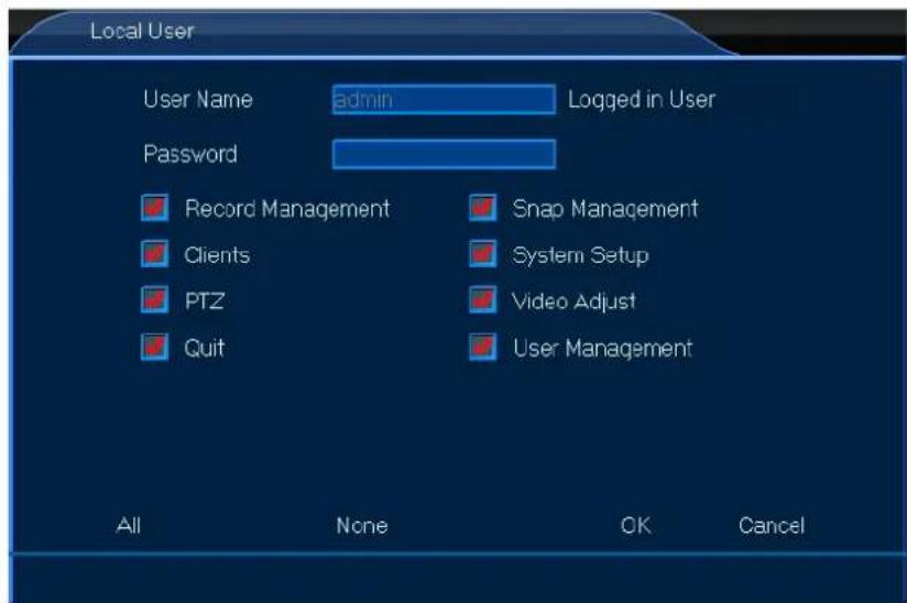
text_image
Local User User Name admin Logged in User Password Record Management Snap Management Clients System Setup PTZ Video Adjust Quit User Management All None OK Cancel- Set up as desired.
- Left-click OK to confirm.
Network User
- Left-click the User icon to enter the menu.
- Check off the Network User box and left-click Add or Edit.
text_image
User User Local User User Group Network User User List admin Add Delete Edit Automatic Logout Wait 5 Min Apply OK Cancel
text_image
Network User User Name admin Connected User Password PTZ Playback System Setup Other CH01 CH02 CH03 CH04 All None OK Cancel- Set up as desired.
- Left-click OK to confirm.
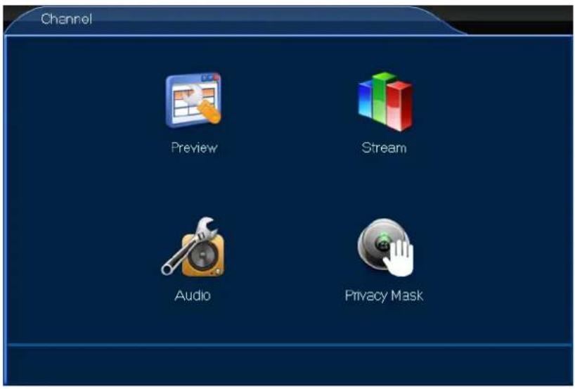
8.2 Channel

- Left-click the General icon to enter the menu.
text_image
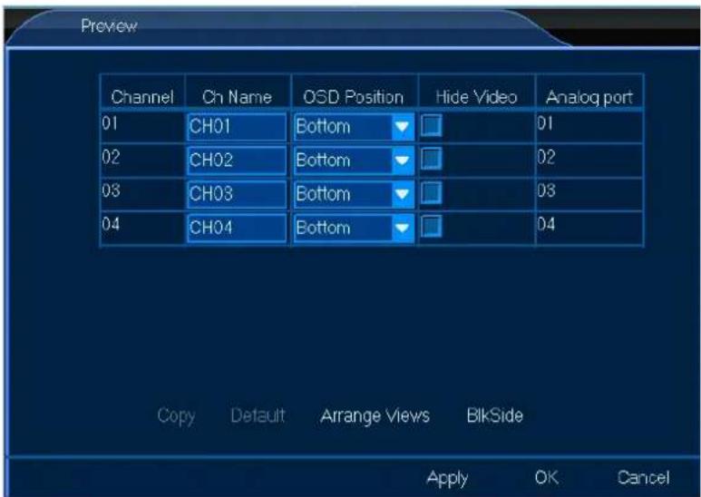
Channel Preview Stream Audio Privacy Mask8.2.1 Preview

The Preview menu allows you to adjust all general on-screen settings such as name position. Proceed as follows:
- Left-click the General icon to enter the menu.
text_image
Preview Channel Cn Name OSD Position Hide Video Analog port 01 CH01 Bottom ▼ □ 01 02 CH02 Bottom ▼ □ 02 03 CH03 Bottom ▼ □ 03 04 CH04 Bottom ▼ □ 04 Copy Default Arrange Views BlikSide Apply OK Cancel- Set up as desired.
- Left-click OK to confirm.
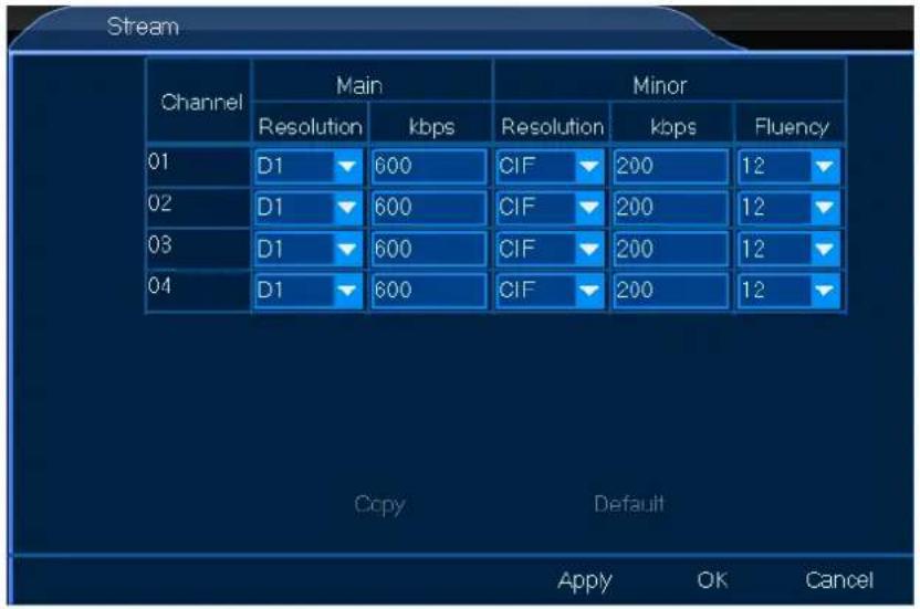
8.2.2 Stream

The Stream menu allows you to adjust the stream settings, either local or over a network. Proceed as follows:
- Left-click the Stream icon to enter the menu.
text_image
Stream Channel Main Minor Resolution kbps Resolution kbps Fluency 01 D1 600 CIF 200 12 02 D1 600 CIF 200 12 03 D1 600 CIF 200 12 04 D1 600 CIF 200 12 Copy Default Apply OK Cancel-
Set up as desired.
-
Left-click OK to confirm.
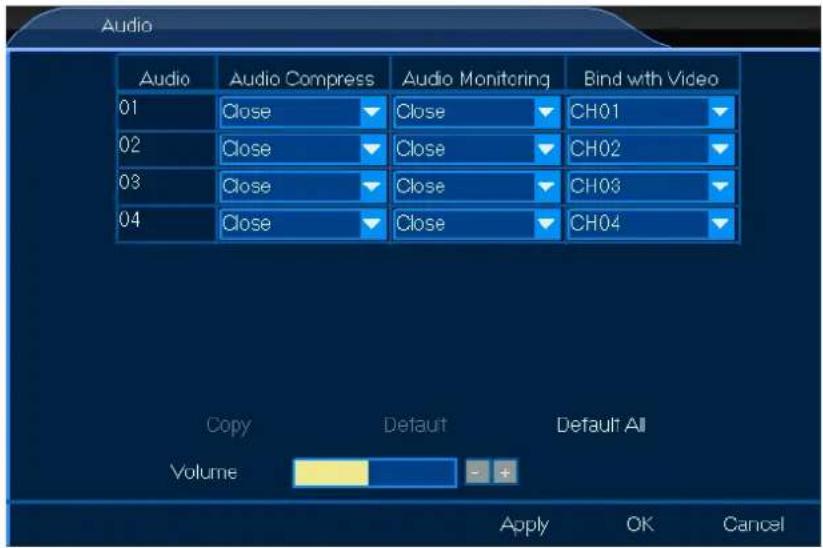
8.2.3 Audio

The Audio menu allows you to adjust all general audio settings. Proceed as follows:
- Left-click the Audio icon to enter the menu.
text_image
Audio Audio Compress Audio Monitoring Bind with Video 01 Close Close CH01 02 Close Close CH02 03 Close Close CH03 04 Close Close CH04 Copy Default Default All Volume Apply OK Cancel-
Set up as desired.
-
Left-click OK to confirm.
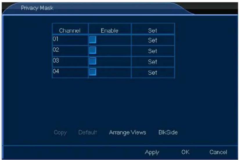
8.2.4 Privacy Mask

The Privacy Mask menu allows you to mask parts – max. 4 – of the channel. Proceed as follows:
- Left-click the Privacy Mask icon to enter the menu.
text_image
Privacy Mask Channel Enable Set 01 Set 02 Set 03 Set 04 Set Copy Default Arrange Views BlkSide Apply OK Cancel- Set up as desired.
- Left-click OK to confirm.
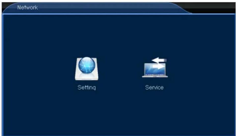
8.3 Network

- Left-click the Network icon to enter the menu.
text_image
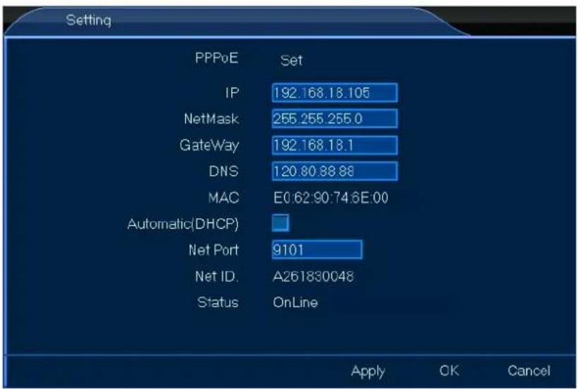
Network Setting Service8.3.1 Setting

The Setting menu allows you to set all general connection settings. Proceed as follows:
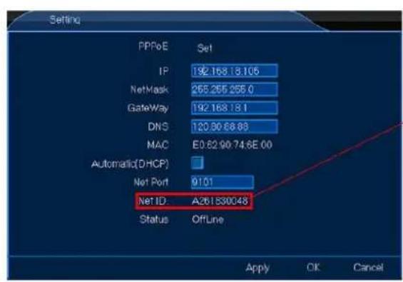
- Left-click the Setting icon to enter the menu.
text_image
Setting PPPoE Set IP 192.168.18.105 NetMask 255.255.255.0 GateWay 192.168.18.1 DNS 120.80.88.88 MAC E0:62:90:74:6E:00 Automatic(DHCP) Net Port 9101 Net ID.A261830048 Status OnLine Apply OK Cancel- Set up as desired.
- Left-click OK to confirm.
8.3.2 Service

The Service menu allows you to set all network settings. These network settings are important if you wish to control your monitoring system remotely. Proceed as follows:
- Left-click the Service icon to enter the menu.
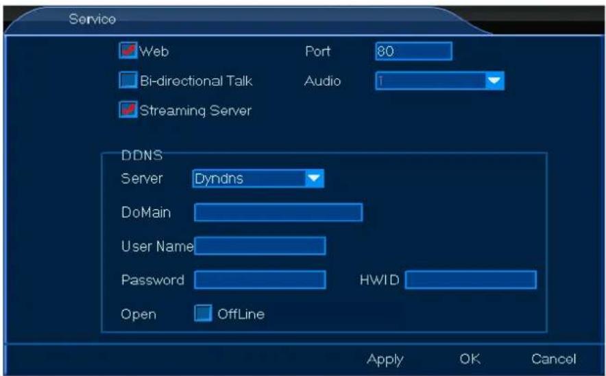
text_image
Service Web Port 80 Bi-directional Talk Audio Streaming Server DDNS Server Dyndns DoMain User Name Password HWID Open OffLine Apply OK Cancel- Set up as desired.
- Left-click OK to confirm.
8.4 Alarm

- Left-click the Alarm icon to enter the menu.
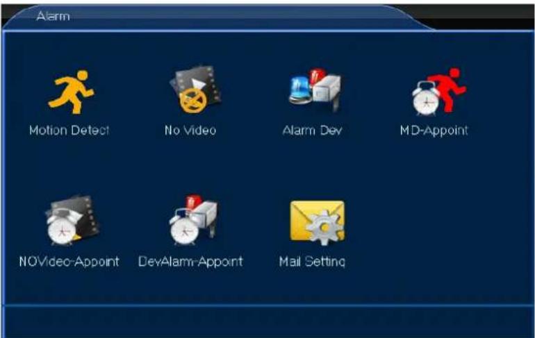
text_image
Alarm Motion Detect No Video Alarm Dev MD-Appoint NOVideo-Appoint DevAlarm-Appoint Mail SettingREMARK
• Refer to chapter 7.2.10 Clear Alarm above for more alarm functions.
8.4.1 Motion Detect

The Motion Detect menu allows you to define your motion detection area. Proceed as follows:
- Left-click the Motion Detect icon to enter the menu.
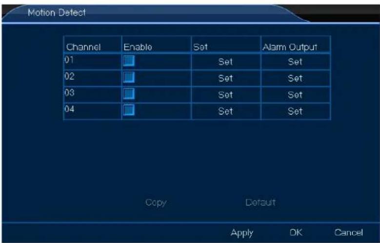
text_image
Motion Detect Channel Enable Set Alarm Output 01 Set Set 02 Set Set 03 Set Set 04 Set Set Copy Default Apply DK CancelCCTVSET2
- Set up as desired.
- Left-click OK to confirm.
8.4.2 No Video

The No Video menu allows you to set the alarm output. Proceed as follows:
- Left-click the No Video icon to enter the menu.
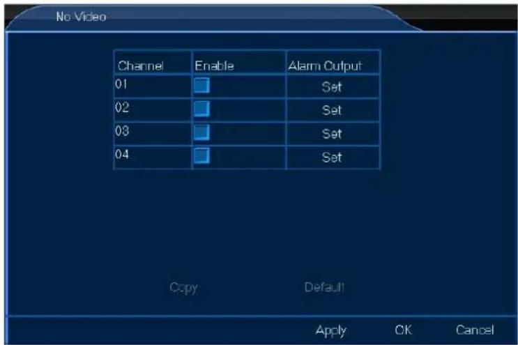
text_image
No Video Channel Enable Alarm Output 01 Set 02 Set 03 Set 04 Set Copy Default Apply OK Cancel- Set up as desired.
- Left-click OK to confirm.
8.4.3 Alarm Dev

The Alarm Dev menu allows you to set the alarm output. Proceed as follows:
- Left-click the Alarm Dev icon to enter the menu.
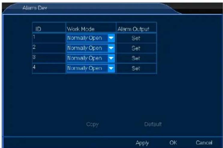
text_image
Alarm Dev ID Work Mode Alarm Output 1 Normally Open Set 2 Normally Open Set 3 Normally Open Set 4 Normally Open Set Copy Default Apply OK CancelCCTVSET2
- Set up as desired.
- Left-click OK to confirm.
8.4.4 MD-Appoint

The MD-Appoint menu allows you to set the motion detection schedule. Proceed as follows:
- Left-click the MD-Appoint icon to enter the menu.
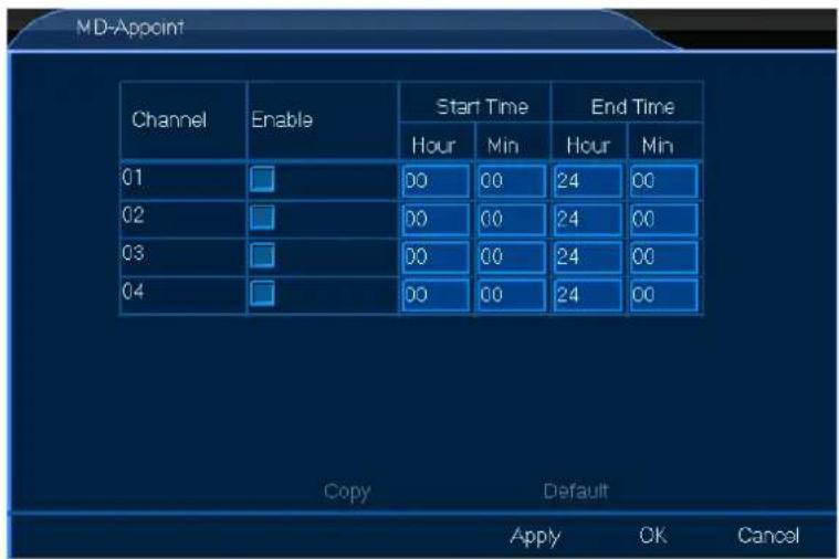
text_image
MD-Appoint Channel Enable Start Time End Time Hour Min Hour Min 01 00 00 24 00 02 00 00 24 00 03 00 00 24 00 04 00 00 24 00 Copy Default Apply OK Cancel- Set up as desired.
- Left-click OK to confirm.
8.4.5 NOVideo-Appoint

The NOVideo-Appoint menu allows you to set the alarm-off schedule. Proceed as follows:
- Left-click the NOVideo-Appoint icon to enter the menu.
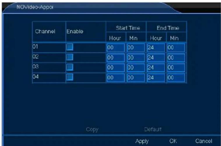
text_image
NOVideo-Appol Channel Enable Start Time End Time Hour Min Hour Min 01 00 00 24 00 02 00 00 24 00 03 00 00 24 00 04 00 00 24 00 Copy Default Apply OK Cancel- Set up as desired.
- Left-click OK to confirm.
8.4.6 DevAlarm-Appoint

The DevAlarm-Appoint menu allows you to set the alarm time schedule. Proceed as follows:
- Left-click the DevAlarm-Appoint icon to enter the menu.
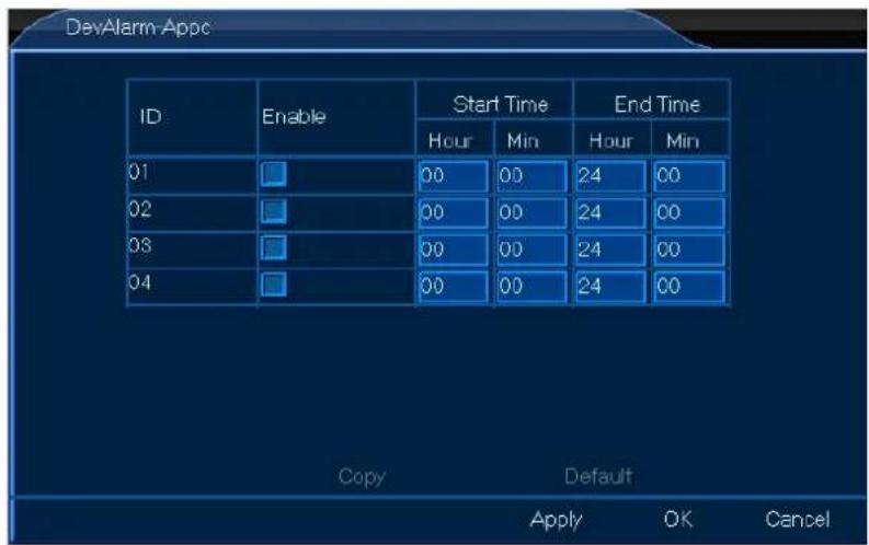
text_image
DevAlarm Appc ID Enable Start Time End Time Hour Min Hour Min 01 00 00 24 00 02 00 00 24 00 03 00 00 24 00 04 00 00 24 00 Copy Default Apply OK Cancel- Set up as desired.
- Left-click OK to confirm.
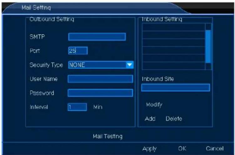
8.4.7 Mail Setting

The Mail Setting menu allows you to set all mail settings. Proceed as follows:
- Left-click the Mail Setting icon to enter the menu.
text_image
Mail Setting Outbound Setting SMTP Port 25 Security Type NONE User Name Password Interval 1 Min Inbound Setting Inbound Site Modify Add Delete Mail Testing Apply OK CancelCCTVSET2
- Set up as desired.
- Left-click OK to confirm.
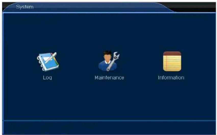
8.5 System

- Left-click the System icon to enter the menu.
text_image
System Log Maintenance Information8.5.1 Log

The Log menu allows you to consult the log-in activity. Proceed as follows:
- Left-click the Log icon to enter the menu.
- Set up as desired.
- Left-click OK to confirm.
8.5.2 Maintenance

The Maintenance menu allows you to update and reset your system. Proceed as follows:
- Left-click the Maintenance icon to enter the menu.
- Set up as desired.
- Left-click OK to confirm.
8.5.3 Information

CCTVSET2
The Information menu allows you to consult general information such as software and hardware version, etc. Proceed as follows:
- Left-click the Information icon to enter the menu.
- Left-click OK to confirm.
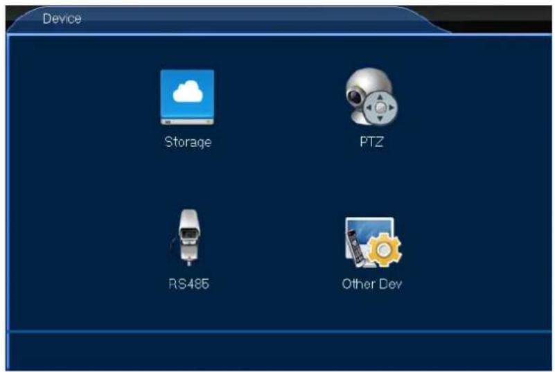
8.6 Device

- Left-click the Device icon to enter the menu.
text_image
Device Storage PTZ RS485 Other Dev8.6.1 Storage

The Storage menu allows you to consult the HDD capacity and to set the recording options in case of a full HDD. Proceed as follows:
- Left-click the Storage icon to enter the menu.
- Set up as desired.
- Left-click OK to confirm.
8.6.2 PTZ

The PTZ menu allows you to set all PTZ settings and protocols. Proceed as follows:
- Left-click the PTZ icon to enter the menu.
- Set up as desired.
- Left-click OK to confirm.
8.6.3 RS485

The RS485 menu is not used on this type of DVR.
8.6.4 Other Dev

The Other Dev menu allows you adjust your monitor settings. Proceed as follows:
- Left-click the Other Dev icon to enter the menu.
- Set up as desired.
- Left-click OK to confirm.
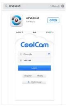
9. ATVCloud
Your CCTVSET2 DVR supports remote surveillance from your mobile phone, either with Android® or with Apple®. To use the system remotely from your mobile phone:
- Search and download the ATVCloud app in the iTunes or Google Play app store.
text_image
ATVCloud 1 Result ATVCloud name you OPEN CoolCam Login Regate Modify Make loger- Register and log in.
- Enter the DVR Net ID.
text_image
Setting PPPoE Set IP 192.168.13.105 NetMask 265.255.255.0 Gateway 192.168.18.1 DNS 120.90.68.88 MAC E0:62.90:74.6E 00 Automatic(DHCP) Net Port 9101 Net ID:A261830048 Status OffLine Apply OK Cancel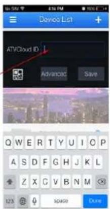
text_image
Device List ATVCloud ID 1 Advanced Save Q W E R T Y U I O P A S D F G H J K L Z X C V B N M 123 90489 Done- You are now set for remote surveillance from your mobile phone!
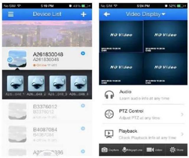
text_image
Device List A261830048 A261830048 Online 9 Wt B26...048.1 A26...048.2 A28...048.3 A26...048.4 B3376012 B3376012 B4087084 B4087084 A26...386 Video Display NO Video NO Video NO Video NO Video Audio Learn audio info at any time PTZ Control Adjust PTZ at any time Playback Check Playback info at any time Capture Megaphone Video More10. CMS Surveillance Software
Please download the manual for the CMS Surveillance software from the Perel website. Go to www.perel.eu, enter [CCTVSET2] in the website's search engine and download the user manual from the product's page.
11. Cleaning and Maintenance
The DVR system does not need any particular maintenance. However, it is advisable to clean it occasionally to keep it looking like new.
12. Technical Specifications
DVR
| video format | PAL |
| video compression | H.264 (FRAME/D1) |
| video input | 4 channels, composite video signal 1 Vp-p / 75 ohms BNC |
| video output | BNC, VGA & HDMI |
| maximum recording rate (PAL) | frame / D1 - 704 x 576 pixels @ 100 IPS (PAL) |
| image quality setting | highest / higher / high / low / lower / lowest |
| hard disk storage | built-in 500 GB hard disk |
| recording mode | manual / timer / motion |
| refresh rate | 100 IPS for PAL |
| motion detection area | 16 x 12 grids per channel |
| motion detection sensitivity | 1 parameter with 6 sensitivity levels |
| backup device | USB flash drive and network backup |
| PTZ control | RS-485 |
| key lock | yes |
| video loss detection | yes |
| camera title | up to 8 characters |
| video adjustments | contrast / brightness / saturation |
| power supply | 12 VDC |
| operating temperature | 10°C ~ 40°C (50°F ~ 104°F) |
| system recovery | system auto recovery after power reconnected |
| dimensions | 258 x 213 x 42 mm |
| weight | 950 g |
CCTVSET2
camera (4x)
| IP rating | IP65 |
| scanning system | PAL |
| pick-up element | CMOS sensor |
| number of pixels | 752 x 582 - PAL |
| resolution | 600 TV lines |
| min. illumination | 0 lux (IR on) |
| IR LEDs | 24 |
| max. IR projection distance | 15 m |
| IR filter | yes |
| video output | 1.0 Vp-p composite, 75 ohms |
| built-in lens | 3.6 mm |
| lens angle | 79° |
| power supply | 12 VDC |
| dimensions | 56 x 54 x 142 mm |
| weight | 220 g |
Use this device with original accessories only. Velleman nv cannot be held responsible in the event of damage or injury resulting from (incorrect) use of this device. For more info concerning this product and the latest version of this manual, please visit our website www.perel.eu. The information in this manual is subject to change without prior notice.
All registered trademarks and trade names are properties of their respective owners and are used only for the clarification of the compatibility of our products with the products of the different manufacturers.
Android is a trademark of Google Inc.
iPad, iPod, iPod touch, iPhone, Mac, iMac, MacBook, PowerBook, Power Mac, Mac OS are trademarks of Apple Inc., registered in the U.S. and other countries.
HDMI is a trademark or registered trademark of HMDI Licensing, LLC in the United States and/or other countries.
© COPYRIGHT NOTICE
The copyright to this manual is owned by Velleman nv. All worldwide rights reserved. No part of this manual may be copied, reproduced, translated or reduced to any electronic medium or otherwise without the prior written consent of the copyright holder.
GEBRUIKERSHANDLEIDING
1. Inleiding
- router: EM4544, EM4571
5. Omschrijving
text_image
Row of app icons including desktop, video, audio, and media-related functionsSchuif over de pictogrammen, om de menunamen weer te geven. Van links naar rechts: System Setup, View Layout, Sequence, Zoom, Video Adjust, PTZ, Snapshot, Photos, Record Setup, Playback, Quit.
flowchart
graph LR
    A["View Layout"] --> B["View 1"]
    A --> C["View 4"]
Volledige schermweergave (View 1) of 4-schermenweergave (View 4) instellen.
7.2.2 Sequence

text_image
Channel Manual Scheduled 01 Set Set 02 Set Set 03 Set Set 04 Set Set Copy Default OK Cancel Current disk remaining capacity can video 60 Day 13 Hour 15 Mintext_image
Channel Manual Scheduled 01 Set Set 02 Set Set 03 Set Set 04 Set Copy Default OK Cancel Current disk remaining capacity can video: No Recordingflowchart
graph LR
    A["Clear Alarm"] --> B["Current Clear All"]
text_image
System Setup General Channel Network Alarm System Device8.2 General

text_image
General General Time User8.1.1 General

text_image
User User User Group Local User Network User User List admin Add Edit Delete Automatic Logout Wait 5 Min Apply OK Cancel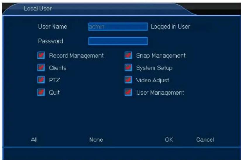
text_image
Local User User Name admin Logged in User Password Record Management Snap Management Clients System Setup PTZ Video Adjust Quit User Management All None OK Canceltext_image
User User Local User User Group Network User User List admin Add Delete Edit Automatic Logout Wait 5 Min Apply OK Cancel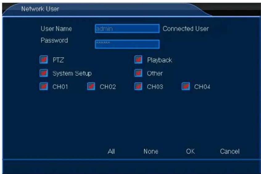
text_image
Network User User Name admin Connected User Password PTZ Playback System Setup Other CH01 CH02 CH03 CH04 All None OK Canceltext_image
Channel Preview Stream Audio Privacy Mask8.2.1 Preview

text_image
Network Setting Service8.3.1 Setting

text_image
Service Web Port 80 Bi-directional Talk Audio Streaming Server DDNS Server Dyndns DoMain User Name Password HWID Open OffLine Apply OK Canceltext_image
Alarm Dev ID Work Mode Alarm Output 1 Normally Open Set 2 Normally Open Set 3 Normally Open Set 4 Normally Open Set Copy Default Apply OK CancelCCTVSET2
text_image
MD-Appoint Channel Enable Start Time End Time Hour Min Hour Min 01 00 00 24 00 02 00 00 24 00 03 00 00 24 00 04 00 00 24 00 Copy Default Apply OK Canceltext_image
NOVideo-Appol Channel Enable Start Time End Time Hour Min Hour Min 01 00 00 24 00 02 00 00 24 00 03 00 00 24 00 04 00 00 24 00 Copy Default Apply OK Canceltext_image
Mail Setting Outbound Setting SMTP Port 25 Security Type NONE User Name Password Interval 1 Min Inbound Setting Inbound Site Modify Add Delete Mail Testing Apply OK CancelCCTVSET2
text_image
System Log Maintenance Information8.5.1 Log

text_image
Device Storage PTZ RS485 Other Dev8.6.1 Storage

natural_image
Row of app icons including tools, screens, gear, and media (no text or symbols)flowchart
graph LR
    A["View Layout"] --> B["View 1"]
    A --> C["View 4"]
bar
| Category | Channel | Mode | Value | |---|---|---|---| | Lightness | 3 | Session 1 | 119 | | Contrast | 0 | 0 | 149 | | Chroma | 0 | 0 | 131 | | Hue | 0 | 0 | 129 | | Sharpness | 0 | 0 | 1 | Copy Save7.2.5 Clients

text_image
Channel Manual Scheduled 01 Set Set 02 Set Set 03 Set Set 04 Set Set Copy Default OK Cancel Current disk remaining capacity can video 60 Day 13 Hour 15 Mintext_image
Channel Manual Scheduled 01 Set Set 02 Set Set 03 Set Set 04 Set Copy Default OK Cancel Current disk remaining capacity can video: No Recordingflowchart
graph LR
    A["Clear Alarm"] --> B["Current Clear All"]
text_image
System Setup General Channel Network Alarm System Device8.2 Général

text_image
General General Time User8.1.1 Général

text_image
User User User Group Local User Network User User List admin Add Edit Delete Automatic Logout Wait 5 Min Apply OK Cancel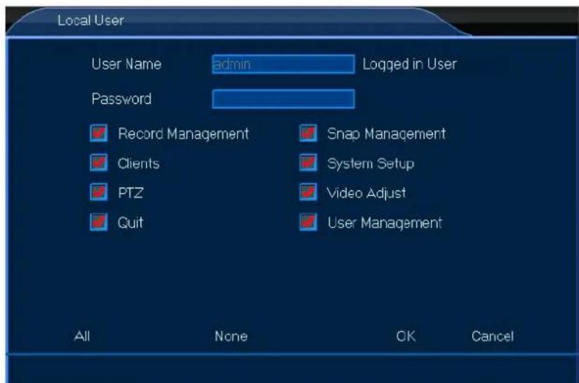
text_image
Local User User Name admin Logged in User Password Record Management Snap Management Clients System Setup PTZ Video Adjust Quit User Management All None OK Canceltext_image
User User Local User User Group Network User User List admin Add Edit Delete Automatic Logout Wait 5 Min Apply OK Cancel
text_image
Network User User Name admin Connected User Password PTZ Playback System Setup Other CH01 CH02 CH03 CH04 All None OK Canceltext_image
Channel Preview Stream Audio Privacy Mask8.2.1 Preview

text_image
Network Setting Service8.3.1 Setting

text_image
Service Web Port 80 Bi-directional Talk Audio Streaming Server DDNS Server Dyndns DoMain User Name Password HWID Open OffLine Apply OK Canceltext_image
Alarm Dev ID Work Mode Alarm Output 1 Normally Open Set 2 Normally Open Set 3 Normally Open Set 4 Normally Open Set Copy Default Apply OK CancelCCTVSET2
text_image
MD-Appoint Channel Enable Start Time End Time Hour Min Hour Min D1 00 00 24 00 D2 00 00 24 00 D3 00 00 24 00 D4 00 00 24 00 Copy Default Apply OK Canceltext_image
NOVideo-Appoi Channel Enable Start Time End Time Hour Min Hour Min 01 00 00 24 00 02 00 00 24 00 03 00 00 24 00 04 00 00 24 00 Copy Default Apply OK Canceltext_image
Mail Setting Outbound Setting SMTP Port 25 Security Type NONE User Name Password Interval 1 Min Inbound Setting Inbound Site Modify Add Delete Mail Testing Apply OK CancelCCTVSET2
text_image
System Log Maintenance Information8.5.1 Log

text_image
Device Storage PTZ RS485 Other Dev8.6.1 Storage

text_image
Video Display NO Video 2014.09.03 10:26:34 CPS NO Video 2014.09.03 10:26:34 CPS NO Video 2014.09.03 10:26:34 CPS Audio Learn audio info at any time PTZ Control Adjust PTZ at any time Playback Check Playback Info at any time Capture Megaphone Video More- router: EM4544, EM4571
5. Descripción
natural_image
Row of app icons including tools, screens, gear, and media (no text or symbols)flowchart
graph LR
    A["View Layout"] --> B["View 1"]
    A --> C["View 4"]
text_image
Channel Manual Scheduled 01 Set Set 02 Set Set 03 Set Set 04 Set Set Copy Default OK Cancel Current disk remaining capacity can video 60 Day 13 Hour 15 Mintext_image
Channel Manual Scheduled 01 Set Set 02 Set Set 03 Set Set 04 Set Copy Default OK Cancel Current disk remaining capacity can video. No Recordingflowchart
graph LR
    A["Clear Alarm"] --> B["Current Clear All"]
text_image
System Setup General Channel Network Alarm System Device8.2 General

text_image
General General Time User8.1.1 General

text_image
User User Local User User Group Network User User List admin Add Edit Delete Automatic Lcqout Wait 5 Min Apply OK Cancel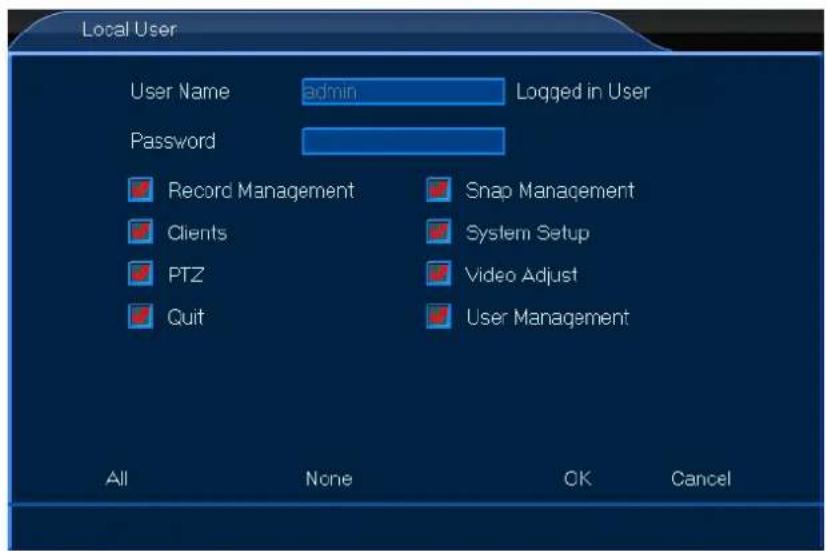
text_image
Local User User Name admin Logged in User Password Record Management Snap Management Clients System Setup PTZ Video Adjust Quit User Management All None OK Canceltext_image
User User Local User User Group Network User User List admin Add Delete Edit Automatic Logout Wait 5 Min Apply OK Cancel
text_image
Network User User Name admin Connected User Password PTZ Playback System Setup Other CH01 CH02 CH03 CH04 All None OK Canceltext_image
Channel Preview Stream Audio Privacy Mask8.2.1 Vista Previa

text_image
Network Setting Service8.3.1 Configuración

text_image
Service Web Port 80 Bi-directional Talk Audio 1 Streaming Server DDNS Server Dyndns DoMain User Name Password HWID Open OffLine Apply OK CancelCCTVSET2
text_image
Alarm Dev ID Work Mode Alarm Output 1 Normally Open Set 2 Normally Open Set 3 Normally Open Set 4 Normally Open Set Copy Default Apply OK CancelCCTVSET2
text_image
MD-Appoint Channel Enable Start Time End Time 01 00 Min Hour Min 02 00 00 24 00 03 00 00 24 00 04 00 00 24 00 Copy Default Apply OK Canceltext_image
NOVideo-Appoi Channel Enable Start Time End Time Hour Min Hour Min 01 00 00 24 00 02 00 00 24 00 03 00 00 24 00 04 00 00 24 00 Copy Default Apply OK CancelCCTVSET2
text_image
Mail Setting Outbound Setting SMTP Port 25 Security Type NONE User Name Password Interval 1 Min Inbound Setting Inbound Site Modify Add Delete Mail Testing Apply OK CancelCCTVSET2
text_image
System Log Maintenance Information8.5.1 Log

text_image
Device Storage PTZ RS485 Other Devtext_image
Video Display NO Video 2014.09.03 10:26:34 CPS NO Video 2014.09.03 10:26:34 CPS NO Video 2014.09.03 10:26:34 CPS Audio Learn audio info at any time PTZ Control Adjust PTZ at any time Playback Check Playback Info at any time Capture Megaphone Video More10. Software de Vigilancia CMS
natural_image
Row of app icons including tools, screens, gear, and media (no text or symbols)flowchart
graph LR
    A["View Layout"] --> B["View 1"]
    A --> C["View 4"]
text_image
Channel Manual Scheduled 01 Set Set 02 Set Set 03 Set Set 04 Set Set Copy Default OK Cancel Current disk remaining capacity can video 60 Day 13 Hour 15 Mintext_image
Channel Manual Scheduled 01 Set Set 02 Set Set 03 Set Set 04 Set Copy Default OK Cancel Current disk remaining capacity can video: No Recordingflowchart
graph LR
    A["Clear Alarm"] --> B["Current Clear All"]
text_image
System Setup General Channel Network Alarm System Device8.2 Allgemeines

CCTVSET2
text_image
General General Time User8.1.1 Allgemeines

text_image
User User Local User User Group Network User User List admin Add Edit Delete Automatic Lcqout Wait 5 Min Apply OK Cancel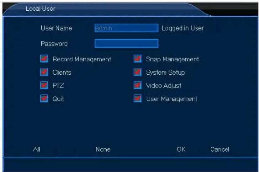
text_image
Local User User Name admin Logged in User Password Record Management Snap Management Clients System Setup PTZ Video Adjust Quit User Management All None OK Canceltext_image
User User Local User User Group Network User User List admin Add Delete Edit Automatic Logout Wait 5 Min Apply OK Cancel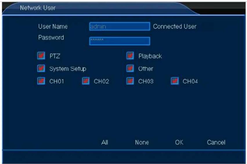
text_image
Network User User Name admin Connected User Password PTZ Playback System Setup Other CH01 CH02 CH03 CH04 All None OK Canceltext_image
Channel Preview Stream Audio Privacy Mask8.2.1 Vorschau

text_image
Network Setting Service8.3.1 Konfiguration

text_image
Service Web Port 80 Bi-directional Talk Audio Streaming Server DDNS Server Dyndns DoMain User Name Password HWID Open OffLine Apply OK Canceltext_image
Alarm Dev ID Work Mode Alarm Output 1 Normally Open Set 2 Normally Open Set 3 Normally Open Set 4 Normally Open Set Copy Default Apply OK Canceltext_image
MD-Appoint Channel Enable Start Time End Time Hour Min Hour Min 01 00 00 24 00 02 00 00 24 00 03 00 00 24 00 04 00 00 24 00 Copy Default Apply OK CancelCCTVSET2
text_image
NOVideo-Appol Channel Enable Start Time End Time Hour Min Hour Min 01 00 00 24 00 02 00 00 24 00 03 00 00 24 00 04 00 00 24 00 Copy Default Apply OK Canceltext_image
Mail Setting Cutbound Setting SMTP Port 25 Security Type NONE User Name Password Interval 1 Min Inbound Setting Inbound Site Modify Add Delete Mail Testing Apply OK Canceltext_image
System Log Maintenance Information8.5.1 Log

text_image
Device Storage PTZ RS485 Other Dev8.6.1 Lagerung

text_image
Video Display NO Video NO Video NO Video Audio Learn audio info at any time PTZ Control Adjust PTZ at any time Playback Check Playback info at any time Capture Megaphone Video More○ monitor VGA & DVI: MONSCA5N
- roteador: EM4544, EM4571
5. Descrição
natural_image
Row of app icons including tools, screens, gear, and media (no text or symbols)flowchart
graph LR
    A["View Layout"] --> B["View 1"]
    A --> C["View 4"]
text_image
Channel Manual Scheduled 01 Set Set 02 Set Set 03 Set Set 04 Set Set Copy Default OK Cancel Current disk remaining capacity can video 60 Day 13 Hour 15 Mintext_image
Channel Manual Scheduled 01 Set Set 02 Set Set 03 Set Set 04 Set Copy Default OK Cancel Current disk remaining capacity can video: No Recordingflowchart
graph LR
    A["Clear Alarm"] --> B["Current Clear All"]
text_image
System Setup General Channel Network Alarm System Device8.2 Geral

text_image
General General Time User8.1.1 Geral

text_image
User User Local User User Group Network User User List admin Add Edit Delete Automatic Logout Wait 5 Min Apply OK Cancel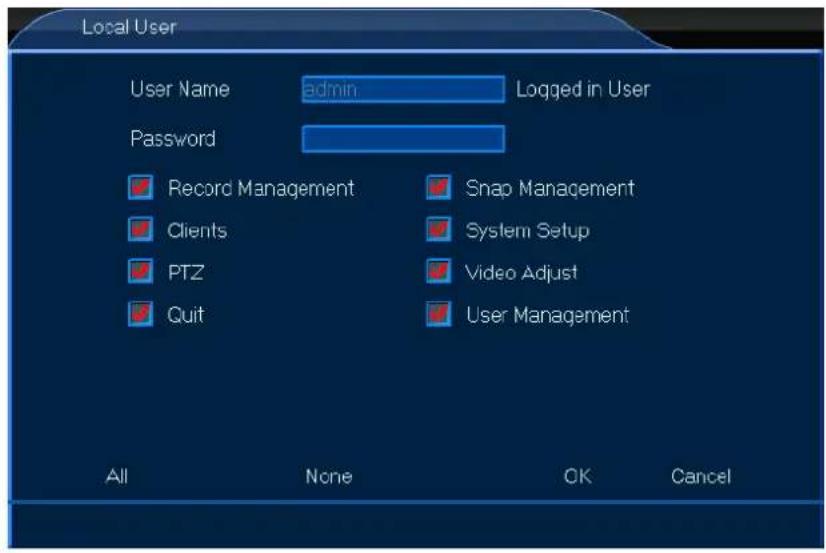
text_image
Local User User Name admin Logged in User Password Record Management Snap Management Clients System Setup PTZ Video Adjust Quit User Management All None OK Canceltext_image
User User User Group Local User Network User User List admin Add Delete Edit Automatic Logout Wait 5 Min Apply OK Cancel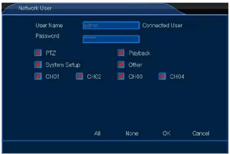
text_image
Network User User Name admin Connected User Password PTZ Playback System Setup Other CH01 CH02 CH03 CH04 All None OK Canceltext_image
Channel Preview Stream Audio Privacy Mask8.2.1 Visualização

text_image
Network Setting Service8.3.1 Configuração

text_image
Service Web Port 80 Bi-directional Talk Audio Streaming Server DDNS Server Dyndns DoMain User Name Password HWID Open OffLine Apply OK Canceltext_image
Alarm Dev ID Work Mode Alarm Output 1 Normally Open Set 2 Normally Open Set 3 Normally Open Set 4 Normally Open Set Copy Default Apply OK CancelCCTVSET2
text_image
MD-Appoint Channel Enable Start Time End Time 01 00 Min Hour Min 02 00 00 24 00 03 00 00 24 00 04 00 00 24 00 Copy Default Apply OK Canceltext_image
NOVideo-Appoi Channel Enable Start Time End Time Hour Min Hour Min 01 00 00 24 00 02 00 00 24 00 03 00 00 24 00 04 00 00 24 00 Copy Default Apply OK CancelCCTVSET2
text_image
Mail Setting Outbound Setting SMTP Port 25 Security Type NONE User Name Password Interval 1 Min Inbound Setting Inbound Site Modify Add Delete Mail Testing Apply OK CancelCCTVSET2
text_image
System Log Maintenance Information8.5.1 Modo Home Arm

text_image
Device Storage PTZ RS485 Other Dev8.6.1 Armazenamento

text_image
Video Display NO Video 2014.09.03 10:26:34 CPS NO Video 2014.09.03 10:26:34 CPS NO Video 2014.09.03 10:26:34 CPS Audio Learn audio info at any time PTZ Control Adjust PTZ at any time Playback Check Playback Info at any time Capture Megaphone Video More10. Software do CMS Surveillance
Velleman® Service and Quality Warranty
Since its foundation in 1972, Velleman® acquired extensive experience in the electronics world and currently distributes its products in over 85 countries.
All our products fulfil strict quality requirements and legal stipulations in the EU. In order to ensure the quality, our products regularly go through an extra quality check, both by an internal quality department and by specialized external organisations. If, all precautionary measures notwithstanding, problems should occur, please make appeal to our warranty (see guarantee conditions).
General Warranty Conditions Concerning Consumer Products (for EU):
- All consumer products are subject to a 24-month warranty on production flaws and defective material as from the original date of purchase.
- Velleman® can decide to replace an article with an equivalent article, or to refund the retail value totally or partially when the complaint is valid and a free repair or replacement of the article is impossible, or if the expenses are out of proportion.
You will be delivered a replacing article or a refund at the value of 100% of the purchase price in case of a flaw occurred in the first year after the date of purchase and delivery, or a replacing article at 50% of the purchase price or a refund at the value of 50% of the retail value in case of a flaw occurred in the second year after the date of purchase and delivery.
- Not covered by warranty:
- all direct or indirect damage caused after delivery to the article (e.g. by oxidation, shocks, falls, dust, dirt, humidity...), and by the article, as well as its contents (e.g. data loss), compensation for loss of profits;
- consumable goods, parts or accessories that are subject to an aging process during normal use, such as batteries (rechargeable, non-rechargeable, built-in or replaceable), lamps, rubber parts, drive belts... (unlimited list);
- flaws resulting from fire, water damage, lightning, accident, natural disaster, etc....;
- flaws caused deliberately, negligently or resulting from improper handling, negligent maintenance, abusive use or use contrary to the manufacturer's instructions;
- damage caused by a commercial, professional or collective use of the article (the warranty validity will be reduced to six (6) months when the article is used professionally);
- damage resulting from an inappropriate packing and shipping of the article;
- all damage caused by modification, repair or alteration performed by a third party without written permission by Velleman®.
- Articles to be repaired must be delivered to your Velleman® dealer, solidly packed (preferably in the original packaging), and be completed with the original receipt of purchase and a clear flaw description.
- Hint: In order to save on cost and time, please reread the manual and check if the flaw is caused by obvious causes prior to presenting the article for repair. Note that returning a non-defective article can also involve handling costs.
- Repairs occurring after warranty expiration are subject to shipping costs.
- The above conditions are without prejudice to all commercial warranties.