ROXXY BLControl 97512 - Remote control toy ROBBE - Free user manual and instructions
Find the device manual for free ROXXY BLControl 97512 ROBBE in PDF.

| Product type | Brushless motor speed controller (ESC) for RC models |
| Brand | Robbe |
| Model | ROXXY BLControl 97512 |
| Dimensions (L x W x H) | 78 x 29 x 14 mm |
| Weight | 79 g |
| Rated / peak current | 75 A / 85 A |
| Number of battery cells | 14 to 36 NiCd/NiMH or 4 to 12 LiPo cells |
| Basic functions | Forward, stop, brake, reverse (depending on mode) |
| Model types | Airplane (AIR), Helicopter (HELI), Boat (BOAT), Car (CAR) |
| Programming | Via throttle stick or optional programming device (Ref. 8642) |
| Programmable settings | Battery type, rotation direction, brake, controller mode, reverse, model type, etc. |
| Integrated technologies | Cool Power FET, Opto (galvanic isolation), RX filter, thermal protection (TP), power-on protection (POR), under-voltage cut-off (PCO), Super Programming System (SPS) |
| Switching frequency (kHz) | 32 kHz |
| Fan | Not integrated (model 97512) |
| Maintenance and cleaning | Avoid contact with grease, oil or water. Ensure sufficient air circulation. |
| Safety | Avoid short circuits, respect polarity, do not put hands in rotating parts, secure the motor firmly. |
| Spare parts and repairability | Use only original robbe spare parts. Warranty is 24 months. |
| General information | 40-page manual, available in multiple languages. Declaration of conformity at www.robbe.com. |
Frequently Asked Questions - ROXXY BLControl 97512 ROBBE
User questions about ROXXY BLControl 97512 ROBBE
0 question about this device. Answer the ones you know or ask your own.
Ask a new question about this device
Download the instructions for your Remote control toy in PDF format for free! Find your manual ROXXY BLControl 97512 - ROBBE and take your electronic device back in hand. On this page are published all the documents necessary for the use of your device. ROXXY BLControl 97512 by ROBBE.
USER MANUAL ROXXY BLControl 97512 ROBBE
6.5 Advance Timing (Motor-Timing)

Brushless motor speed controller in the latest Cool Power FET Technology; thereby offering a high performance in a wide range of applications for aircraft, boats, cars and electric heli models. The controller is particularly suitable for the ROXXY range of Brushless motors, but will also suit other Brushless motors from other manufacturers. Please read carefully the instructions before connecting and operating.
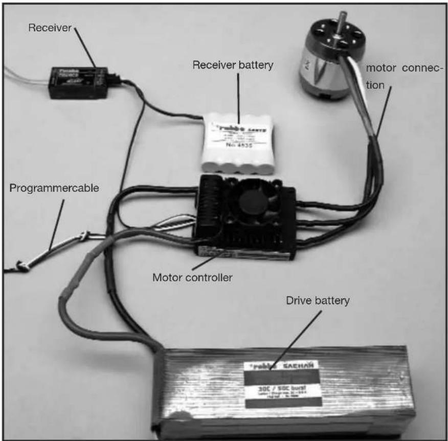
1. Connections, special features
Prepare the red positive and the black negative battery cables for suitable plug/socket connectors. Isolate all solder connections with heat shrink. Connect a suitable battery to the Receiver (Rx) and take note of the Rx manufacturers recommendations! Receiver, Receiver battery, Motor connection, Programmer cable Speed controller, Power battery
- Specification
| BL 975-12 OptoNo. 8639 | BL 9100-12 OptoNo. 8640 | BL 9120-12 OptoNo. 8641 | |
| Function (Choice) Forward-Stop-Brake-Reverse | |||
| Load current: 75 A 100 A 120 A | |||
| Peak load: 85 A 120 A 150 A | |||
| Dimensions (mm): 78x29x14 73,4x56x31 73,4x56x31 | |||
| Weight (g): 79 g 162 g 166 g | |||
| Cell number: | 14...36 NC/ NiMH4...12 LiPo | 14...36 NC/ NiMH4...12 LiPo | 14...36 NC/ NiMH4...12 LiPo |
| SPS: yes yes yes | |||
| Rx-Filter: yes yes yes | |||
| PCO: | yes yes yes | ||
| POR: | yes yes yes | ||
| hec: | 32 kHz | 32 kHz | 32 kHz |
| TP: | yes yes yes | ||
| Cool Power FET: | yes yes yes | ||
| Cooling fan: | - | yes yes | |
3. Programming the stick positions
NOTE!
The model type must be chosen (Parameter 4 or Parameter 5).
Otherwise the new parameters will not be stored.
3.1 Programming the stick positions "forward", "stop" and "reverse"
- Connect the controller according to the above photo graph (with the exception of the power battery)
- Turn on the Tx and move the throttle stick fully for ward.
- Connect Power Battery to the controller.
- The controller will confirm connection with a short beep.
- After approximately 10 seconds you will hear a double beep as confirmation of the fully forward position.
- Move throttle stick to closed position, a short beep will confirm.
- Finally move the throttle stick to the reverse position; a triple beep confirms the programming of the reverse position.
Note:
If after (step 3.1.2) the red LED illuminates, then the SERVO-REVERSE function must be operated in the Tx, remove power supply, reconnect and restart the programming (step 3.1.1).
The fully forward position of the stick must be set near the mechanical stick limit.
3.2 Programming the stick positions "forward" and "stop"
Programming the forwards and stop stick positions of the controller should only be used in forwards operation (no reverse!); this is made in a same manner up to step 3.1.6. The programmed stick positions are confirmed with a triple beep.
4. Programming the speed controller parameters
4.1 Programming the speed controller parameters without using the Programmer
Five parameters may be programmed in this manner.
Entry into programming mode is made by:
- Controller connected as per the above photograph (except the Power Battery)
- Turn Tx on and move throttle stick to forward position.
- Connect Rx battery supply
- Controller will beep to confirm.
- After approximately 10 seconds, you will hear a double beep and after a further 3 seconds, a triple beep will be heard.
Parameter 1 has been chosen when the controller continuously emits single beeps and the LED flashes.
The following stick movements set the program Parameters: Move the throttle stick to closed position and quickly return to full throttle. The controller will indicate the effective programming of Parameter 2 by a continuing double beep and flash of the LED.
For programming Parameters 3, 4 and 5 the sequence described above must be followed.
| Parameter type Beep LED | |||
| Parameter 1 Battery type 1 x 1 x | |||
| Parameter 2 Direction of motor rotation 2 x 2 x | |||
| Parameter 3 | - Brake ON / OFF (AIR)- Brake ON / OFF (HELI)- Reverse ON / OFF (CAR, BOAT) | 3 x 3 x | |
| Parameter 4 Model type AIR / HELI 4 x 4 x | |||
| Parameter 5 Model type BOAT / CAR 5 x 5 x | |||
To change the Parameters, the throttle stick must be moved quickly from full throttle to the stop position and held for a minimum of 3 seconds in the stop position.
To set the parameters, move the throttle stick from the stop position to full throttle and back.
| Parameter type | LED ONBeep every 2 Sec. | LED flashesBeep every 0,5 Sec. |
| Battery type LiPo NiCD/NiMH | ||
| Direction of rotation Normal | Reverse | |
| Brake (AIR)Governor (HELI)Reverse (CAR, BOAT) | OFFOFFOFF | ONONON |
| Model type(AIR / HELI) | AIR | HELI |
| Model type(BOAT / CAR) | BOAT | CAR |
Moving the throttle stick quickly from stop to forward position stories the changes.
Completing and storing the programmed settings is made by momentarily removing the power supply battery.
The controller is now programmed and ready for operation.
4.2 Characteristics, protective functions
POR: start protection, stops involuntary starting of the motor
PCO: Low voltage cut-off, the motor will be stopped before the voltages reaches a level where control is lost and potential deep discharge damage to the cells can occur.
SPS: Super Programming System
Cool Power FET: Latest generation power transistor
Opto: Galvanic separation of the motor interference and receiver.
Rx-Filter: switches the controller OFF when a transmitter signal is not present or corrupted.
TP: Thermal Protection
Hec: High motor frequency
4.3 Programming example
In the following example, the setting up of the controller will be made with the stick positions method and followed by the programming of the model type: AIR (power model) and brake ON used as an example.
4.3.1 Programming the stick positions
- Switch the transmitter on, and move the throttle stick to the "forward" position.
- Connect the drive battery to the speed controller (unit emits a brief beep).
- After about ten seconds a double series of beeps confirms that it has detected the "stick forward" position.
- Move the throttle stick to the "stop" position. A brief series of beeps confirms that the controller has detected the "stop" position.
- Disconnect the drive battery from the speed controller.

4.3.2 Programming the controller parameters
- Switch the transmitter on, and move the throttle stick to the "forward" position.
- Connect the drive battery to the speed controller (unit emits a brief beep).
- After about ten seconds you will hear a double series of beeps, followed by a triple series of beeps after a further three seconds.
- The controller is now in programming mode for Parameter 1 (continuous single beeps and LED flashes).
- Select Parameter 4 by moving the throttle stick four times from the "forward" position to the "stop" position and back to the "forward" position again (continuous quadruple beeps and LED flashes).
- To change the parameter you must first move the throttle stick from the "forward" position to the "stop" position, leaving the throttle stick at the "stop" position for at least three seconds.
- Select the "Air" mode (beep sounds / LED lights up every two seconds).
- The change is stored by moving the throttle stick from the "stop" position to the "forward" position.

4.3.3 Setting Air Brake On
- When you have stored the setting as described above, the speed controller returns to parameter select: Parameter 4.
- Select Parameter 3 by moving the throttle stick four times from the "forward" position to the "stop" position and back to the "forward" position again (continuous triple beeps and LED flashes).
- To change the parameter you must first move the throttle stick from the "forward" position to the "stop" position, leaving the throttle stick at the "stop" position for at least three seconds.
- The controller now displays the currently set brake function: Air Brake ON (beep sounds / LED flashes every 0.5 seconds) or Air Brake OFF (beep sounds / LED lights up every two seconds). If you wish to change the parameter, move the throttle stick rapidly from the "stop" position to the "forward" position and back.
- The change is stored by moving the throttle stick from the "stop" position to the "forward" position.
- Disconnect the speed controller from the drive battery.
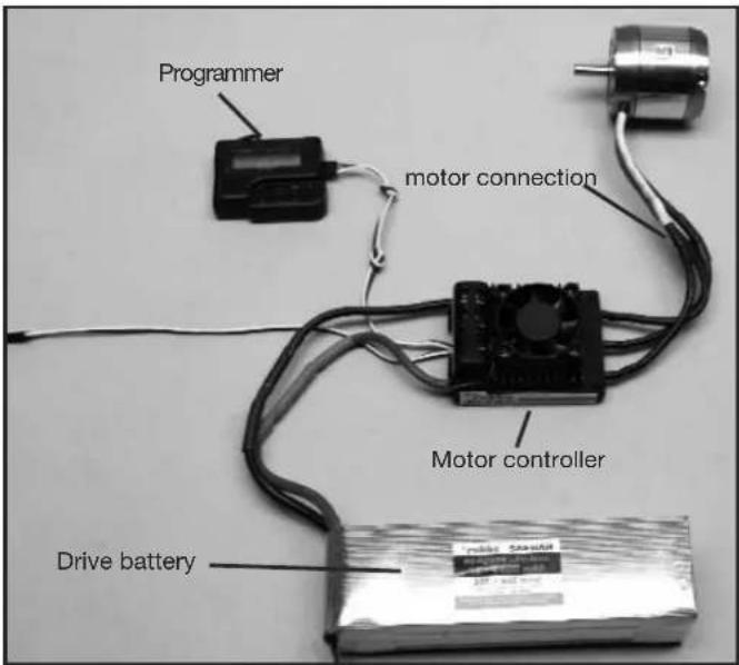
5. Using the Programmer to change settings
Use the robbe Programme No.8642 will enable the easy and efficient programming of the controller to suit the model specific requirements.
This clear, user-friendly unit allows quick and secure programming to be made via the unit's LCD.
5.1 Connecting the Programmer
5.2 Navigating using the Programmer
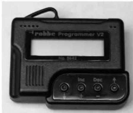
The operation of the Programmer is extremely simple. Using the outer arrow buttons cursor up or down to arrive at your choice of programming mode.
Furthermore, one can change the model type when depressing both arrow buttons. The middle buttons DEC (-) and INC (+) serves to choose and alter the settings.
5.3 Overview of programming facilities
With the exception of a few minor differences between the three modes, all program modes are similarly arranged in a menu format; these are listed in the table below:
| Helicopter Boat / Car Aircraft | ||
| Select Battery Select Battery | Select Battery | |
| Cut Off Voltage Cut Off Voltage | Cut Off Voltage | |
| Cut Off Type Cut Off Type Cut Off Type | ||
| Motor Direction Motor Direction | Motor Direction | |
| Advance Timing Advance Timing | Advance Timing | |
| Acceleration Acceleration Acceleration | ||
| Start Power Start Power | Start Power | |
| Response of Governor | Reverse Function | Air Brake Type |
| Governor On / Off | Motor pole Num | Airbrake On/Off |
| Motor Pole Num | Gear Ratio | Motor pole Num |
| Gear Ratio | Max. RPM Gear Ratio | |
| Max. RPM | Average RPM | Max. RPM |
| Average RPM | Down Load | Average RPM |
| Down Load | Restore Mem. | Down Load |
| Restore Mem. Backup Mem. | Restore Mem. | |
| Backup Mem. | Backup Mem. |
6. PROGRAMMING IN DETAIL
6.1 Battery type

Use the DEC or INC button to set the desired battery type. When you have selected the new battery type you may find that the previously set "CUT OFF VOLTAGE" and "CUT OFF TYPE" parameters have changed. The DEC and INC buttons are always used to set the modes.
6.2 Cut Off Voltage

The Cut Off voltage is determined by the selected battery type. With LiPo in Auto Mode, then the controller cuts off at 3V per cell; a NiCad will be 5.5 V total voltage. Adjust these values using DEC and INC buttons. The scale is from 4.5-50 Volt.
6.3 Cut Off Type

In Cut Off Type mode you can select the cut-off method when battery voltage falls to the set threshold. The options are "Soft Off" or "Hard Off". Use the DEC and INC buttons to set the modes.
6.4 Motor Direction

In Motor Direction mode you can select the direction of rotation of your motor: the two options are normal and reversed.
6.5 Advance Timing

Advance Timing is an alternative term for motor timing. This mode alters the advance of the rotational field, which has a similar effect to "advancing the ignition point". In general terms a setting of 8^ is suitable for most motors. If you wish to use a special set-up for your motor, we recommend the following ranges of values: 0^ to 10^ for in-runner motors, and 15^ to 25^ for out-runner motors.
6.6 Acceleration

In Acceleration mode you can set how fast the controller runs up to maximum speed. This is important if the throttle function is assigned to a switch, as it determines the delay, i.e. the speed with which the motor ramps up to "full-throttle".
Example: Lowest acceleration or Highest acceleration.
Variable parameters:
Lowest / Low / Normal / High / Highest, set using the DEC and INC buttons.
6.7 Start Power

In the Start Power menu you can set the level of power (torque) which the motor produces initially, i.e. from a stand-still. If you are using the controller in a model helicopter, the value should be small in order to avoid premature gear wear. The available values are Lowest / Low / Normal / High / Highest.
6.8 Air Brake Type

When in Air mode (model aircraft), the controller's motor brake effect can be adjusted, enabling the user to decide whether the motor comes to a halt gradually or suddenly. You can select the modes Slow / Normal / Fast, or a percentage setting (5 - 100% - 100% equates to a sudden stop) using the DEC and INC buttons.
6.9 Air Brake On / Off - Air mode only
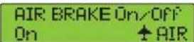
This menu point is used for switching the motor brake on or off.
6.10 Reverse function (Boat and Car modes only)

In Boat or Car mode the Reverse function is used for selecting whether the motor works only in one direction of rotation, or in forward and reverse. In "One Way" mode (only one direction of rotation) the motor's direction of rotation can also be selected: the two options are forward and reverse.
In "Two Way" mode the speed controller is set up for forward / reverse operation. Caution: changing the direction or motor rotation may cause the cancellation of other settings.
6.11 Governor Response - Helicopter mode only

This mode is used for setting the characteristics of the speed controller in speed governor (regulator) mode. The available options are Slowest / Slow / Normal / Fast / Fastest.
Caution: the faster the value you select, the higher the current drawn from the battery. We recommend that you select a fairly low setting in order to avoid premature damage to the speed controller and / or the flight battery.
6.12 Governor On / Off - Helicopter mode only

This mode is used for switching speed governor (regulator) operation on and off. Governor mode stabilises the pre-set rotational speed and keeps it virtually constant. The options are: "On" mode for stabilised, or "Off" mode for non-stabilised.
6.13 Motor Pole Number
MOTOR POLE NUM 2 POLE HELI
In Motor Pole Number mode you can enter the number of poles in your motor. This value is important for indicating the exact rotational speed. The available range extends from 2 to 36 poles.
6.14 Gear Ratio
GEAR RATIO 1.0 : i HELI
This mode allows you to enter the individual gearbox ratio you are using. The value for rotational speed indication is calculated using the number of motor poles and the gearbox reduction ratio. The available range of values is from 1.0 : 1 to 25.0 : 1.
6.15 Max. RPM & Average RPM
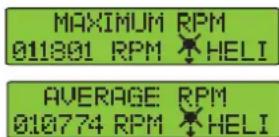
This mode shows you the maximum and average rotational speeds recorded during the last flight, taking into account the values set under Points 6.14 and 6.15.
6.16 Down Load
DOWN LOAD REALLY? No HELI
Download mode is used for writing (transferring) set values to the speed controller. Press the INC button to start the process, and the Programmer then beeps once every second until the procedure is complete. If you wish to interrupt the process, simply press the DEC button.
6.17 Restore Memory
RESTORE MEMORY REALLY? No HELI
Restore Memory is used to access values which have been stored in the Programmer's own memory. Press the INC button to start the process, and the Programmer then beeps once every second until the procedure is complete. If you wish to interrupt the process, simply press the DEC button.
6.18 Backup Memory
BACKUP MEMORY REALLY? No HELI
Backup Memory mode allows you to store permanently the selected values in the Programmer's integral memory. Press the INC button to start the process, and the Programmer then beeps once every second until the procedure is complete. The values set on the speed controller itself are not affected by this action.
If you wish to interrupt the process, simply press the DEC button.
7. GUARANTEE
We guarantee this speed controller for a period of 24 months. Proof for the commencement and conclusion of this guarantee period is provided by your receipt from the model shop, which you obtained when you purchased the product. Any repairs carried out under guarantee do not extend the original guarantee period. During this period we will correct any operating faults, production defects and material faults which arise, at no charge to you. We will not entertain any claims beyond these terms, e.g. consequent damage.
The unit must be returned to us carriage-paid; it will also be returned to you carriage-paid. We will not accept goods sent to us without prepaid carriage. We accept no liability for transit damage and the loss of your shipment; we therefore recommend that you take out suitable insurance to cover these risks. Send the unit to the Service Centre responsible for your country. The following conditions must be fulfilled if we are to process your guarantee claim:
- Send proof of purchase (till receipt) with your shipment.
- The unit must have been operated in accordance with the operating instructions.
- The unit must have been operated with the recommended power sources and genuine robbe accessories.
- The unit must not exhibit damage due to damp, unauthorised intervention, excessive voltage, overload conditions or mechanical damage.
- Please include a concise, accurate description of the fault or defect.
8. SAFETY NOTES
• Take notice of the controller technical data
- Maintain correct polarity of all connections
- Avoid short-circuits at all costs
- Install the controller so that it cannot come into contact with oil, grease and water.
- Ensure sufficient air circulation for cooling
- Avoid bodily contact with all rotating parts whilst operating
- Securely mount the motor and restrain all cables.
We reserve the right to introduce technical modifications.
9. CONFORMITY DECLARATION
robbe Modellsport GmbH & Co. KG hereby declares that this product satisfies the fundamental requirements and other relevant regulations contained in the following Directives:
- Law regarding radio system and telecommunications apparatus (FTEG) and Directive 1999/5/EG (R&TTE)
- Directive RL 2004/108/EG (Electro-magnetic compatibility)
- Directive LVD 72-23 / 93/68 EWG (Low Voltage Directive)
The original Conformity Declaration can be viewed on the Internet under www.robbe.com: click on the logo button marked "Conform" which is included in each device description.
Généralités
6.5 Advance Timing (Timing Motore)

6.5 Advance Timing (timing motor)

natural_image
Symbol of a waste bin with crossed lines indicating no waste, and a solid black rectangle below (no text or labels)This symbol means that you must dispose of electrical and electronic equipment separately from the general household waste when it reaches the end of its useful life. Take your unwanted equipment to your local specialist waste collection point or recycling centre. This applies to all countries of the European Union, and to other European countries with a separate waste collection system.
We accept no liability for errors and technical modifications.
Copyright robbe Modellsport 2009
This document may not be copied or reproduced in whole or in part without the prior written approval of robbe Modellsport GmbH & Co. KG