TBS TB 50 - Heating AEG - Free user manual and instructions
Find the device manual for free TBS TB 50 AEG in PDF.
| Product type | Heating mat for floor (direct floor heating) |
| Brand | AEG |
| Model | TBS TB 50 (Series 160/1-8 and Set 160/1-8) |
| Heating surface | From 1 to 8 m² depending on model |
| Connected power | 160 W to 1280 W depending on length |
| Power supply | 230 V, 50 Hz, single-phase |
| Surface power | 160 W/m² |
| Linear load of heating cable | 10 W/m |
| Nominal limit temperature | 80 °C |
| Protection rating | IPX7 (temporary immersion) |
| Mat dimensions | Width 500 mm, length from 2 to 16 m (depending on area) |
| Compatible floor coverings | Tile, carpet, PVC, parquet, cork (with specified max. thicknesses) |
| Thermostat included | Model FRTD 903 (only in Set version) |
| Temperature sensor | Integrated, to be placed at the center of the cable loops |
| Use | Domestic, floor temperature balancing (bathroom, kitchen, etc.) |
| Installation | By a professional installer only |
| Measurement checks | 3 mandatory measurements (unpacking, after laying, after covering) |
| Warranty | Subject to conditions (completed warranty card mandatory) |
| Maintenance | No special maintenance required |
| Safety instructions | Respect distances, do not damage the cable, use a residual current device ≤ 30 mA |
Frequently Asked Questions - TBS TB 50 AEG
User questions about TBS TB 50 AEG
0 question about this device. Answer the ones you know or ask your own.
Ask a new question about this device
Download the instructions for your Heating in PDF format for free! Find your manual TBS TB 50 - AEG and take your electronic device back in hand. On this page are published all the documents necessary for the use of your device. TBS TB 50 by AEG.
USER MANUAL TBS TB 50 AEG
Operation and installation 15
natural_image
Pure diagram of a coiled spring on grid background (no text or symbols)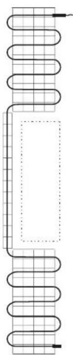
natural_image
Pure diagram of a coiled spring with grid lines and a rectangular block, no text or symbols present.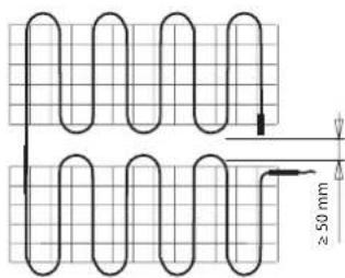
text_image
≥ 50 mm
natural_image
Diagram of a coiled spring with grid lines and a pointer, no text or symbols present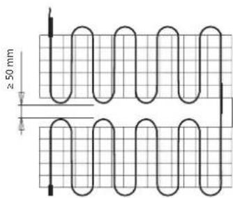
text_image
≥ 50 mm
natural_image
Pure diagram of a coiled spring on grid paper with no text or symbols26_07_29_0108
natural_image
Diagram showing a pair of scissors cutting through a patterned fabric (no text or symbols)26 07 29 0094
Isolationswiderstand (MΩ): ....
Sicherung (A): ....
- General information....15
- Safety 16
- Settings.....16
- Cleaning, care and maintenance 16
- Troubleshooting 16
INSTALLATION
- Safety 17
- Appliance description....17
- Preparations....17
- Installation....19
- Commissioning....22
- Handover 22
- Specification 23
GUARANTEE
ENVIRONMENT AND RECYCLING
SPECIAL INFORMATION
• The appliance may be used by children aged 8 and up and persons with reduced physical, sensory or mental capabilities or a lack of experience and know-how, provided that they are supervised or they have been instructed on how to use the appliance safely and have understood the resulting risks. Children must never play with the appliance. Children must never clean the appliance or perform user maintenance unless they are supervised.
• The connection to the power supply must be in the form of a permanent connection. Ensure the appliance can be separated from the power supply by an isolator that disconnects all poles with at least 3 mm contact separation.
• The power cable must only be replaced by a qualified contractor using original spare parts.
• Fix the appliance in position as described in chapter "Installation / Preparations".
OPERATION
1. General information
The chapters "Special Information" and "Operation" are intended for both the user and qualified contractors. The chapter "Installation" is intended for qualified contractors.

Note
Read these instructions carefully before using the appliance and retain them for future reference. Pass on the instructions to a new user if required.
1.1 Safety instructions
1.1.1 Structure of safety instructions

KEYWORD Type of risk
Here, possible consequences are listed that may result from failure to observe the safety instructions. » Steps to prevent the risk are listed.
1.1.2 Symbols, type of risk
| Symbol | Type of risk |
| Injury | |
| Electrocution |
1.1.3 Keywords
| KEYWORD | Meaning |
| DANGER | Failure to observe this information will result in serious injury or death. |
| WARNING Failure | Failure to observe this information may result in serious injury or death. |
| CAUTION | Failure to observe this information may result in non-serious or minor injury. |
1.2 Other symbols in this documentation

Note
General information is identified by the adjacent symbol.
» Read these texts carefully.
| Symbol Meaning | |
| Material losses(appliance damage, consequential losses and environmental pollution) | |
| Appliance disposal | |
» This symbol indicates that you have to do something. The action you need to take is described step by step.
1.3 Information on the appliance
| Symbol Meaning | |
| Underfloor heating system (direct action) | |
1.4 Units of measurement

Note
All measurements are given in mm unless stated otherwise.
2. Safety
2.1 Intended use
The heating mat provides direct underfloor heating and is used for electric underfloor heating in individual areas, e.g. bathrooms, kitchens, sauna lobbies, hallways or other living areas and in indoor swimming pools and other wet rooms.
This appliance is intended for domestic use. It can be used safely by untrained persons. The appliance can also be used in a non-domestic environment, e.g. in a small business, as long as it is used in the same way.
Any other use beyond that described shall be deemed inappropriate. Observation of these instructions and of instructions for any accessories used is also part of the correct use of this appliance.
2.2 General safety instructions

WARNING Injury
The appliance may be used by children aged 8 and up and persons with reduced physical, sensory or mental capabilities or a lack of experience and know-how, provided that they are supervised or they have been instructed on how to use the appliance safely and have understood the resulting risks. Children must never play with the appliance. Children must never clean the appliance or perform user maintenance unless they are supervised.

Material losses
Only operate the heating mat when fully installed and with all safety equipment fitted.
2.3 CE designation
The CE designation shows that the appliance meets all essential requirements according to the:
- Electromagnetic Compatibility Directive
- Low Voltage Directive
2.4 Test symbols
See type plate label, label on the warranty card or in the main junction box.
3. Settings
You can set the required floor temperature by means of an external temperature controller.
The floor temperature which can be achieved depends on the floor structure and the floor covering. Observe the information in the operating and installation instructions for the temperature controller.
3.4.1 Temperature controller with time switch
Energy saving operation is ensured by installing a temperature controller with time switch.
Using a temperature controller with time switch means that you can adapt the heating operation to your lifestyle by specifying when the heating mat will switch on and off.
» Adjust the operating times so that it switches on a certain amount of time before use. The necessary time depends on the floor structure and the floor covering.
» Adjust the time it switches off so that the appliance switches off approximately half an hour before the end of use.
Further information can be found in the operating and installation instructions for the temperature controller.
4. Cleaning, care and maintenance
The heating mat does not require any particular maintenance.
5. Troubleshooting
| Problem | Cause | Remedy |
| The heating mat does not provide the necessary heating output. | The temperature controller is not set correctly. | Adjust the temperature controller to the maximum heating level. After waiting for a short time, check whether the floor is warming up. |
| For temperature controllers with a time switch: Operating times are not set correctly. | Check the time switch operating times and adjust if necessary. | |
| There is no power. | Check whether the fuses/MCBs in your fuse box have blown/ responded. If the fuses/MCBs blow/ respond repeatedly, notify your heating contractor. |
If you cannot remedy the fault, notify your qualified contractor. To facilitate and speed up your request, provide the number from the type plate (000000-0000-000000).
You will find the type plate on the warranty card in these instructions and in the main junction box.
INSTALLATION
6. Safety
Only a qualified contractor should carry out installation, commissioning, maintenance and repair of the appliance.
6.1 General safety instructions
We guarantee trouble-free operation and operational reliability only if the accessories intended for the appliance are used.
6.2 Instructions, standards and regulations

Material losses
Never install the heating mat on highly or normally flammable materials.

Material losses
Never switch on the heating mat when it is rolled up.

Note
Observe all applicable national and regional regulations and instructions.
7. Appliance description
The heating mat is a surface heating element. The heating mat comprises a heating conductor which is coiled over a self-adhesive fabric.
The heating mat is glued directly to the screed or to levelling compound (e.g. floating screed). The heat generated by the heating mat is thus transferred directly to the floor.
The required floor temperature is set via an external temperature controller. The temperature controller is equipped with a temperature sensor. The temperature sensor must be installed at heating level.

text_image
1 2 3 4 5 26_07_29_0100_1 Heating conductor
2 Temperature sensor
3 Conduit (tube for installing the temperature sensor)
4 Female connection for heating conductor/cold lead
5 Cold lead (electrical power cable)
The heating mat is switched on or off according to the floor temperature set on the temperature controller.
The temperature controller takes account of heat gain, e.g. due to sunlight or lighting, and provides frost protection.
The temperature controller is self-monitoring. In the event of a power failure, sensor break or sensor short-circuit, the heating automatically switches off.
7.1 Standard delivery
TBS TB 50 160/1-8
- Heating mat
- Two type plate labels (warranty card / main junction box)
TBS TB 50 Set 160/1-8
- Heating mat
- Conduit (ø 10 mm) with sensor well
- Anti-kink bend
• Temperature controller FRTD 903 - Temperature sensor
- Two type plate labels (warranty card / main junction box)
7.2 Warranty card / installation diagram
You must complete the warranty card and installation diagram fully. The warranty is not valid without this proof. The chapter "Preparations" contains information on completing the installation diagram.
8. Preparations
8.1 Installation site / Installation conditions

Material losses
Do not install the heating mat at temperatures below 5 °C.

Note
In new builds, allow the screed to cure for 4-6 weeks. Only install the heating mat once this period has ended.
8.1.1 Substrate

Material losses
The heating mat may only be installed on floors. Walls or ceilings may not be used as installation surfaces.
You may install the heating mat on a variety of substrates, e.g. screed, hot mix asphalt or moisture-resistant chipboard. Observe the following information:
• Installation on hot mix asphalt: The substrate must be able to withstand temperatures of approx. 80 °C.
• Installation on chipboard: Suitable insulation boards can also be installed to improve impact sound insulation.
- Very sandy screed surfaces must be coated with an adhesive dispersion.
Thermal insulation
Thermal insulation must be fitted between the unfinished floor and the heating mat.
» Please ensure that the thermal insulation complies with the latest standards.
8.1.2 Bathrooms and shower rooms
The heating mat must not be installed in areas where sanitary equipment such as baths, showers, freestanding WCs, etc. are to be installed.
8.1.3 Floor coverings
The heating mat is suitable for use with a range of floor coverings, e.g. tiles, carpets, PVC or parquet.

Material losses
Only use floor coverings which are suitable for underfloor heating systems.
Note that different floor coverings have different thermal conductivity values according to their type and the thickness of the material:
| Floor covering Max. thickness Thermal conductivity | ||
| Tiles 30 mm | = 1.00 W/( m · K) | |
| Carpet 20 mm | = 0.09 W/( m · K) | |
| Parquet 16 mm | = 0.14 W/( m · K) | |
| PVC 10 mm | = 0.23 W/( m · K) | |
| Cork 10 mm | = 0.08 W/( m · K) | |
8.1.4 Covering the floor
Additional floor coverings, e.g. carpets, may lead to higher temperatures in the floor itself.
» Do not use floor coverings which are more than 10 mm thick.
8.2 Safety clearances

Material losses
Cupboards which cover the whole area must not be placed on heated areas.
» Make sure that you leave a 60 cm wide unheated edge area along the walls.
» Make sure that you observe a distance of at least 30 mm from all conductive materials.

Material losses
The heating conductors on heating mats installed in parallel must not touch.
» Make sure that you observe a distance of at least 50 mm when installing heating mats in parallel.
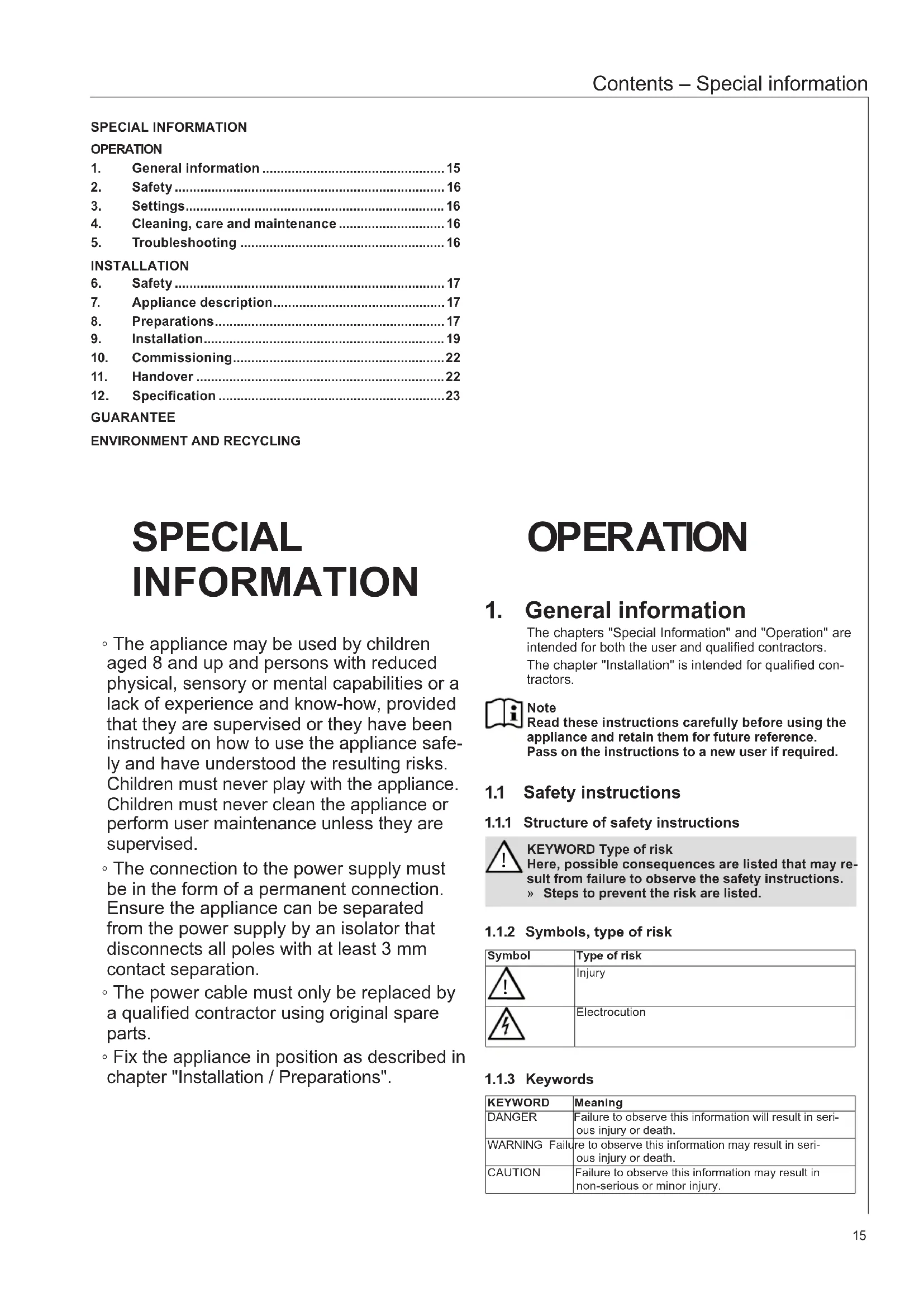
8.3 Installation diagram
You must draw up an installation diagram before installing the heating mat. See chapter "Sample installations" and "Safety clearances" in this respect.
» Draw the position of the heating mats, the unheated edge area, the temperature sensor and the cold lead on the installation diagram.
8.3.1 Sample installations

text_image
Technical diagram showing various coil and spring coil configurations with dimension annotations in millimeters26_07_29_0108
8.3.2 Position of the temperature sensor
The temperature sensor must be positioned directly below the heating mat and approx. 100 mm from the edge of the heating mat.
- The temperature sensor must be positioned halfway between two heating conductor loops.
- The temperature sensor lead must not cross or touch the heating conductor.
8.4 Test measurement 1
Before installation, please check the total resistance and insulation resistance of the heating mats in their delivered condition.

Note The warranty is not valid without proof of this measurement.
» Measure the total resistance and insulation resistance of the heating mat.
» Check whether the measured values are in the permissible measuring range (see chapter "Specification / Data table").
» Enter the measured values on the warranty card.
8.5 Preparing the substrate
» Make sure that the substrate is clean, dry, solid and free from dirt and grease.
» Make sure that no sharp edges or pointed objects are protruding from the floor. These could damage the heating conductor.
» If the substrate is not level, carry out levelling operations so as to avoid cavities beneath the heating conductor. Settlement joints in the substrate must not be bridged using the heating mat.
9. Installation
9.1 Installing a flush box
Please install all power cables in a flush box for connection to the temperature controller.

Material losses In bathrooms and wet rooms, the flush box must only be installed outside safety zone 2.

text_image
1 2 3 4 5 26_07_29_0009_1 Distribution cable (NYM 3x1.5 mm ^2 )
2 Flush box
3 Conduit for temperature sensor
4 Temperature sensor
5 Cold lead / conduit for cold lead
1 Distribution cable (NYM 3x1.5 mm ^2 )
2 Flush box
3 Conduit for temperature sensor
4 Temperature sensor
5 Cold lead / conduit for cold lead
» Choose an appropriate position to install the flush box.
» Install an additional flush box if you would like to connect more heating mats.
» Always install an additional flush box if the cold lead or temperature sensor lead is too short.
9.2 Installing temperature sensors
The temperature sensor must be installed in a conduit. The conduit is included as standard in the set.
» Choose an appropriate position for installing the conduit. Observe the instructions in chapter "Installation diagram / Position of the temperature sensor".
» Install the conduit and insert the temperature sensor into it.
9.3 Installing the cold lead
You can install the cold lead in a conduit or flush with the floor in a groove in the screed.
9.3.1 Installing in a conduit

Material losses
The cold lead must be installed in a separate conduit. The cold lead and the temperature sensor lead must not be installed in the same conduit.
» Install an additional conduit and install the cold lead in the conduit.
» Make sure that the female connection for the heating conductor/cold lead is not subjected to a tensile load of more than 120 N.
9.3.2 Installation in the floor

Material losses
If installed in the floor, the cold lead must be able to be inserted in the flush box without an extension. The cold lead may not cross or touch the heating conductor.
» Chisel out a groove in the screed by using appropriate tools and install the cold lead in this groove.
» Make sure that the female connection for the heating conductor/cold lead is not subjected to a tensile load of more than 120 N.
9.4 Laying out the heating mat

Material losses
Do not cut, squash or kink the heating conductor on the heating mat.
You may shorten and extend the cold lead as long as you do not change its cross-section.

Material losses
» Do not use nails or other metal objects to attach the heating mat to the floor.
» Only stand on the heating mat if absolutely necessary. Take any necessary protective measures to avoid mechanical damage (e.g. shoes with rubber soles).

Material losses
» Do not install the heating mat through or beneath insulating material.
» The installed heating mat may not cross expansion joints in the floor.
» Do not use penetrating fixing materials in the vicinity of the heating mat, e.g. screws and rawl plugs for door stoppers, WC fittings.
Observe the position of the heating mat specified in the installation diagram for the subsequent steps.
» Lay out the heating mat in accordance with the installation diagram. The self-adhesive side must be facing downwards.

natural_image
Diagram showing a pair of coiled fabric strips with scissors cutting through them, no text or symbols present26_07_29_0094_
» Cut the heating mat backing fabric with scissors at the turning point. Make sure that you don't accidentally damage the heating conductor with the scissors.

Material losses
The heating conductor bending radius must be at least 18 mm. The smallest permissible bending radius is six times the diameter of the heating conductor.
» Carefully bend the heating conductor at the cutting point.
» Observe minimum distances (see chapter "Preparations / Safety clearances").
» Make sure that the temperature sensor lead does not cross or touch the heating conductor and that the temperature sensor is halfway between two heating conductor loops.
» Make sure that heating mats do not overlap. Overlapping heating mats may lead to malfunctions.
» Make sure that the fabric is laid out without any creases.
» Press the heating mat firmly onto the floor.
9.5 Test measurement 2
After laying out the heating mat, check the total resistance and insulation resistance of the heating mat to rule out the possibility of damage to the heating mat.

Note
The warranty is not valid without proof of this measurement.
» Measure the total resistance and insulation resistance of the heating mats.
» Check whether the measured values are in the permissible measuring range (see chapter "Specification / Data table").
» Enter the measured values on the warranty card.
» Replace the damaged heating mat if the measured values deviate from the permissible range.
9.6 Laying the floor covering

Material losses
Only use tile adhesive and levelling compound which are suitable for underfloor heating systems and which can withstand constant temperatures of at least 80 °C.

Material losses
When applying tile adhesive and levelling compound, please observe the manufacturer's instructions concerning drying time and other manufacturer's information.

Note
You must wait at least 3 days, depending on the humidity levels within the building, before starting to lay the floor covering.
9.6.1 Tiles
» Select an appropriate tile adhesive or levelling compound if applicable. Note that this must be able to withstand constant temperatures of at least 80 °C.
» Seal the conduits so that tile adhesive cannot get into the conduits whilst installing the heating mats.
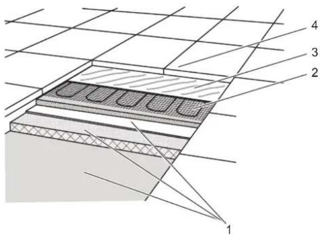
text_image
1 2 3 426 07 29 0004
1 Substrate with thermal insulation
2 Heating mat with heating conductor
3 Tile adhesive
4 Floor covering
» Apply the tile adhesive and levelling compound if applicable. Take care not to damage the heating conductor.
» Make sure that the entire circumference and length of the heating conductor is enclosed in tile adhesive.
» If necessary, lift the heating mat slightly after applying the tile adhesive to make sure that there are no air bubbles beneath the heating mat. These may lead to higher temperatures.
» Press the heating mat back down into the tile adhesive.
» Lay the tiles in accordance with the manufacturer's instructions.
9.6.2 Carpet, PVC, parquet or cork
Before laying floor coverings such as carpet, PVC or cork, cover a large area of the heating mat with a levelling compound.
The levelling compound provides mechanical protection for the heating mats. Appropriate materials include free-flowing cement mortar, for example.
» Choose an appropriate levelling compound. Note that this must be able to withstand constant temperatures of at least 80 °C.
» Seal the conduits so that levelling compound cannot get into the conduits whilst installing the heating mats.
» Apply the levelling compound in a 5-10 mm thick layer. Take care not to damage the heating conductor.
» Make sure that the entire circumference and length of the heating conductor is enclosed in levelling compound.
» If necessary, lift the heating mat slightly after applying the levelling compound to make sure that there are no air bubbles beneath the heating mat. These may lead to higher temperatures.
» Press the heating mat back down into the levelling compound.
» Allow the levelling compound to cure in accordance with manufacturer's instructions.
» Fill settlement joints with suitable materials, e.g. silicone.
» Lay the floor covering in accordance with the manufacturer's instructions.
9.7 Test measurement 3
After laying the floor covering, check the total resistance and insulation resistance of the heating mat to rule out the possibility of damage to the heating mats.

Note
The warranty is not valid without proof of this measurement.
» Measure the total resistance and insulation resistance of the heating mats.
» Check whether the measured values are in the permissible measuring range (see chapter "Specification / Data table").
» Enter the measured values on the warranty card.
9.8 Power supply

WARNING Electrocution
Carry out all electrical connection and installation work in accordance with relevant regulations. Observe the local requirements of the relevant power supply utility.

WARNING Electrocution
Only use a permanent connection to the power supply.
» Separate the appliance from the power supply by an additional isolator that disconnects all poles with at least 3 mm contact separation. Use mains isolators, fuses, contactors, etc. for this purpose.
» Install an RCD with a nominal earth leakage current of ≤ 30 mA.

Material losses
The heating conductor must not be connected to the power supply.
» Only connect the cold lead to the power supply.

Material losses
Observe the type plate. The specified voltage must match the mains voltage.
Design all materials in accordance with the rated consumption of the appliance.
Basic wiring diagram
(e.g. for temperature controller FRTD 903)
The basic wiring diagram below is provided for clarification purposes. The temperature controller wiring diagram is the only applicable wiring diagram (see operating and installation instructions for the temperature controller).

text_image
L N PE NLNL 123456 t° 1 285_07_21_0002
1 Heating mat
2 Temperature sensor
In connection with the following installation steps, observe the operating and installation instructions for the temperature controller:
» Connect the earth conductor to the earth connection (PE).
» Connect the heating mats to the temperature controller via the cold lead.
» Check whether the earth conductor is connected correctly.
9.8.1 Connecting additional heating mats

Material losses
Only connect additional heating mats in parallel.
» Make sure that the total current does not exceed the maximum switching current and breaking capacity of the temperature controller.
» Information can be found in the operating and installation instructions for the temperature controller.
10. Commissioning
10.1 Initial start-up
After installing the heating mat and applying tile adhesive or levelling compound, you must wait at least 2 days before switching on the heating mat for the first time.
» Switch on the heating mat for short periods over several days once this initial drying phase has been completed. This ensures that the tile adhesive and levelling compound cure slowly.
» If you have laid impermeable synthetic floor coverings, you must heat the floor for a period of approx. 36 hours. This ensures that there will be no residual humidity left in the floor.

Note
Final commissioning can take place no sooner than 5 days after completion of the floor.
10.2 Commissioning report
» Make sure that you have completed the warranty card and the installation diagram correctly. Observe the following information:
- The installation diagram must show the exact position of the heating mats, cold leads and temperature sensor.
• Measured values from all three test measurements must be entered on the warranty card.
» Enter the measured total resistance and insulation resistance on both type plate labels.
» Attach the type plate label for the warranty card to the specified position on this card.
» Attach the type plate label for the main junction box in a highly visible location on this box.
11. Handover
Explain the functions of the appliance to the user. Draw special attention to the safety instructions.
Hand over these operating and installation instructions to the user.
Hand over the warranty card and installation diagram to the user.
12. Specification
12.1 Data table
12.1.1 TBS TB 50 160/1-8
| TBS TB50 160/1 | TBSTB 50160/1,5 | TBS TB50 160/2 | TBSTB 50160/2.5 | TBS TB50 160/3 | TBS TB50 160/4 | TBS TB50 160/5 | TBS TB50 160/6 | TBS TB50 160/7 | TBS TB50 160/8 | ||
| 234267 | 234268 | 234269 | 234270 | 234271 | 234272 | 234273 | 234274 | 234275 | 234276 | ||
| Electrical details | |||||||||||
| Connected load | W | 160 | 240 | 320 | 400 | 480 | 640 | 800 | 960 | 1120 | 1280 |
| Power supply | 1/N/PE~230 V50Hz | 1/N/PE~230 V50Hz | 1/N/PE~230 V50Hz | 1/N/PE~230 V50Hz | 1/N/PE~230 V50Hz | 1/N/PE~230 V50Hz | 1/N/PE~230 V50Hz | 1/N/PE~230 V50Hz | 1/N/PE~23O V50Hz | 1/N/PE~230 V50Hz | |
| Electrical resistance (+10/-5 %) | Ω | 330,0 | 206,8 | 156,9 | 123,5 | 102,7 | 78,8 | 63,1 | 52,3 | 40,8 | 35,9 |
| Dimensions | |||||||||||
| Length | mm | 2000 | 3000 | 4000 | 5000 | 6000 | 8000 | 10000 | 12000 | 14000 | 16000 |
| Width | mm | 500 | 500 | 500 | 500 | 500 | 500 | 500 | 500 | 500 | 500 |
| Surface | m2 | 1 | 1,5 | 2 | 2,5 | 3 | 4 | 5 | 6 | 7 | 8 |
| Versions | |||||||||||
| IP-Rating | IPX7 | IPX7 | IPX7 | IPX7 | IPX7 | IPX7 | IPX7 | IPX7 | IPX7 | IPX7 | |
| Values | |||||||||||
| Area-specific output | W/m2 | 160 | 160 | 160 | 160 | 160 | 160 | 160 | 160 | 160 | 160 |
| Heat conductor load | W/m | 10 | 10 | 10 | 10 | 10 | 10 | 10 | 10 | 10 | 10 |
| Rated limit temperature, heating element | °C | 80 | 80 | 80 | 80 | 80 | 80 | 80 | 80 | 80 | 80 |
12.1.2 TBS TB 50 Set 160/1-8
| TBS TB50 Set160/1 | TBS TB50 Set160/1,5 | TBS TB50 Set160/2 | TBS TB50 Set160/2,5 | TBS TB50 Set160/3 | TBS TB50 Set160/4 | TBS TB50 Set160/5 | TBS TB50 Set160/6 | TBS TB50 Set160/7 | TBS TB50 Set160/8 | ||
| 234277 | 234278 | 234279 | 234280 | 234281 | 234282 | 234283 | 234284 | 234285 | 234286 | ||
| Electrical details | |||||||||||
| Connected load | W | 160 | 240 | 320 | 400 | 480 | 640 | 800 | 960 | 1120 | 1280 |
| Power supply | 1/N/PE~ 230 V50Hz | 1/N/PE~ 230 V50Hz | 1/N/PE~ 230 V50Hz | 1/N/PE~ 230 V50Hz | 1/N/PE~ 230 V50Hz | 1/N/PE~ 230 V50Hz | 1/N/PE~ 230 V50Hz | 1/N/PE~ 230 V50Hz | 1/N/PE ~ 230 V50Hz | 1/N/PE~ 230 V50Hz | |
| Electrical resistance (+10/-5 %) | Ω | 330,0 | 206,8 | 156,9 | 123,5 | 102,7 | 78,8 | 63,1 | 52,3 | 40,8 | 35,9 |
| Dimensions | |||||||||||
| Length | mm | 2000 | 3000 | 4000 | 5000 | 6000 | 8000 | 10000 | 12000 | 14000 | 16000 |
| Width | mm | 500 | 500 | 500 | 500 | 500 | 500 | 500 | 500 | 500 | 500 |
| Surface | m^2 | 1 | 1,5 | 2 | 2,5 | 3 | 4 | 5 | 6 | 7 | 8 |
| Versions | |||||||||||
| IP-Rating | IPX7 | IPX7 | IPX7 | IPX7 | IPX7 | IPX7 | IPX7 | IPX7 | IPX7 | IPX7 | |
| Values | |||||||||||
| Area-specific output | W/m^2 | 160 | 160 | 160 | 160 | 160 | 160 | 160 | 160 | 160 | 160 |
| Heat conductor load | W/m | 10 | 10 | 10 | 10 | 10 | 10 | 10 | 10 | 10 | 10 |
| Rated limit temperature, heating element | °C | 80 | 80 | 80 | 80 | 80 | 80 | 80 | 80 | 80 | 80 |
Guarantee
The warranty conditions of our German companies do not apply to appliances acquired outside of Germany. In countries where our subsidiaries sell our products, it is increasingly the case that warranties can only be issued by those subsidiaries. Such warranties are only granted if the subsidiary has issued its own terms of warranty. No other warranty will be granted.
We shall not provide any warranty for appliances acquired in countries where we have no subsidiary to sell our products. This will not affect warranties issued by any importers.
Environment and recycling
We would ask you to help protect the environment. After use, dispose of the various materials in accordance with national regulations.
Warranty card
Customer
Name
Street
Postcode/Town
Telephone
Customer
Electrician
Date laid
Date installed
Company stamp
Purpose

Cement screed

Wooden floor

Type plate
Test report
This warranty is only valid if the warranty card is completed fully. The insulation resistance must be > 1 M Ohm.
Test measurement 1 (in the delivered condition)
Date
Signature
Before installing the heating mat, the following values were measured:
Total resistance ____ Ohm
Insulation resistance ____ M Ohm
Test measurement 2 (after laying out the heating mat)
Date
Signature
After laying out the heating mat, the following values were measured:
Total resistance ____ Ohm
Insulation resistance ____M Ohm
Test measurement 3 (after laying the floor covering)
Date
Signature
After laying the floor covering, the following values were measured:
Total resistance ____ Ohm
Insulation resistance ____ M Ohm
Installation diagram
Please create an accurate drawing of the room, the installed heating mats and the floor sensor.
| 1 | 23 | 456 | 789 | 101 | 112 | 314 | 151 | 1617 | 181 | 920 | 212 | 223 | 242 | 252 | 262 | 2728 | 293 | 3031 | 323 | 334 | 353 | 6 | ||||||||||||||||
| 1 | ||||||||||||||||||||||||||||||||||||||
| 2 | ||||||||||||||||||||||||||||||||||||||
| 3 | ||||||||||||||||||||||||||||||||||||||
| 4 | ||||||||||||||||||||||||||||||||||||||
| 5 | ||||||||||||||||||||||||||||||||||||||
| 6 | ||||||||||||||||||||||||||||||||||||||
| 7 | ||||||||||||||||||||||||||||||||||||||
| 8 | ||||||||||||||||||||||||||||||||||||||
| 9 | ||||||||||||||||||||||||||||||||||||||
| 10 | ||||||||||||||||||||||||||||||||||||||
| 11 | ||||||||||||||||||||||||||||||||||||||
| 12 | ||||||||||||||||||||||||||||||||||||||
| 13 | ||||||||||||||||||||||||||||||||||||||
| 14 | ||||||||||||||||||||||||||||||||||||||
| 15 | ||||||||||||||||||||||||||||||||||||||
| 16 | ||||||||||||||||||||||||||||||||||||||
| 17 | ||||||||||||||||||||||||||||||||||||||
| 18 | ||||||||||||||||||||||||||||||||||||||
| 19 | ||||||||||||||||||||||||||||||||||||||
| 20 | ||||||||||||||||||||||||||||||||||||||
| 21 | ||||||||||||||||||||||||||||||||||||||
| 22 | ||||||||||||||||||||||||||||||||||||||
| 23 | ||||||||||||||||||||||||||||||||||||||
| 24 | ||||||||||||||||||||||||||||||||||||||
| 25 | ||||||||||||||||||||||||||||||||||||||
| 26 | ||||||||||||||||||||||||||||||||||||||
| 27 | ||||||||||||||||||||||||||||||||||||||
| 28 | ||||||||||||||||||||||||||||||||||||||
| 29 | ||||||||||||||||||||||||||||||||||||||
| 30 | ||||||||||||||||||||||||||||||||||||||
| 31 | ||||||||||||||||||||||||||||||||||||||
| 32 | ||||||||||||||||||||||||||||||||||||||
| 33 | ||||||||||||||||||||||||||||||||||||||
| 34 | ||||||||||||||||||||||||||||||||||||||
| 35 | ||||||||||||||||||||||||||||||||||||||
| 36 | ||||||||||||||||||||||||||||||||||||||
| 37 | ||||||||||||||||||||||||||||||||||||||
| 38 | ||||||||||||||||||||||||||||||||||||||
| 39 | ||||||||||||||||||||||||||||||||||||||
| 40 |
Date installed: ....
Model:
Total resistance (Ω): ....
Insulation resistance (MΩ): ....
Fuse (A): ....
RCD (mA): ....
REMARQUES PARTICULIÈRES
UTILISATION
text_image
Technical diagram showing various coil and spring coil configurations with dimension annotations in millimetersnatural_image
Diagram showing a pair of scissors cutting through a wavy fabric pattern (no text or symbols)26 07 29 0094
text_image
Technical diagram showing various coil and spring coil configurations with dimension annotations in millimeters26_07_29_0108
natural_image
Diagram showing scissors cutting through a wavy fabric pattern with a hatched background (no text or symbols)26_07_29_0094_
text_image
Technical diagram showing various coil and spring coil configurations with dimension annotations in millimeters26 07 29 0108
natural_image
Diagram showing scissors cutting through a wavy fabric pattern with a grid background (no text or symbols)text_image
Technical diagram showing various coil and spring coil configurations with dimension annotations in millimetersnatural_image
Diagram showing scissors cutting through a wavy fabric pattern with a grid background (no text or symbols)26_07_29_0094_
Urzhumskaya street 4,
building 2
129343 Moscow
Tel. 0495 7753889
Fax 0495 7753887
Switzerland
STIEBEL ELTRON AG
Industrie West
Gass 8
5242 Lupfig
Tel. 056 4640-500
Fax 056 4640-501