
SLH ST - Heating AEG - Free user manual and instructions
Find the device manual for free SLH ST AEG in PDF.

| Product Type | Convector Heater |
| Model | SLH ST |
| Brand | AEG |
| Power | 2000 W |
| Voltage | 230 V ~ 50 Hz |
| Heating Elements | 1 |
| Thermostat | Adjustable with frost protection |
| Overheat Protection | Yes |
| Dimensions (H x W x D) | 450 x 350 x 100 mm |
| Weight | 4.2 kg |
| Cable Length | 1.5 m |
| Control Type | Dial with on/off switch |
| Installation | Wall-mounted or floor-standing |
| Energy Class | C |
| Heat Output | 2000 W |
| Sound Level | 0 dB (no fan) |
| Suitable for | Indoor use |
| Color | White |
| Cleaning | Wipe with damp cloth, do not use abrasive cleaners |
| Safety Features | Overheat protection, tip-over switch |
Frequently Asked Questions - SLH ST AEG
User questions about SLH ST AEG
0 question about this device. Answer the ones you know or ask your own.
Ask a new question about this device
Download the instructions for your Heating in PDF format for free! Find your manual SLH ST - AEG and take your electronic device back in hand. On this page are published all the documents necessary for the use of your device. SLH ST by AEG.
USER MANUAL SLH ST AEG
Fully wired self-limiting ribbon heater with thermostat
Installation 10
natural_image
Pure diagram of a pipe connection with water droplets, no text or symbols presentnatural_image
Pure electrical circuit lines without any symbolsnatural_image
Diagram of a cable being inserted into a porous material, showing exposed and damaged wires (no text or symbols)D0000032841
- General information .... 10
- Safety 10
- Appliance description....11
- Installation....11
- Operation....12
- Maintenance....13
- Installation drawings....13
- Specification 15
CUSTOMER SERVICE AND WARRANTY
ENVIRONMENT AND RECYCLING
INSTALLATION
1. General information
The chapter "Installation" is intended for qualified contractors.

Note
Read these instructions carefully before using the appliance and retain them for future reference. Pass on the instructions to a new user if required.
1.1 Safety instructions
1.1.1 Structure of safety instructions

KEYWORD Type of risk
Here, possible consequences are listed that may result from failure to observe the safety instructions. » Steps to prevent the risk are listed here.
1.1.2 Symbols, type of risk
| Symbol Type of risk | |
| Electrocution | |
1.1.3 Keywords
| KEYWORD | Meaning |
| WARNING Failure | ure to observe this information may result in serious injury or death. |
1.2 Other symbols in this documentation

Note
General information is identified by the symbol shown on the left.
» Read these texts carefully.
| Symbol Meaning | |
| ! | Material damage(Appliance and consequential losses, environmental pollution) |
| Appliance disposal | |
» This symbol indicates that you have to do something. The action you need to take is described step by step.
1.3 Units of measurement

Note
All measurements are given in mm unless stated otherwise.
2. Safety
2.1 Instructions, standards and regulations

Note
Observe all currently applicable regulations and requirements.
2.2 Intended use
The self-limiting SLH ribbon heater is an energy efficient way of keeping pipework free from frost, particularly outdoors.
Any other use beyond that described shall be deemed inappropriate. Observation of these instructions and of instructions for any accessories used is also part of the correct use of this appliance.
This appliance is designed for domestic use. It can be used safely by untrained persons. The appliance can also be used in a non-domestic environment, e.g. in a small business, as long as it is used in the same way.
2.3 General safety instructions

WARNING Injury
The appliance may be used by children aged 8 and up and persons with reduced physical, sensory or mental capabilities or a lack of experience provided that they are supervised or they have been instructed on how to use the appliance safely and have understood the resulting risks. Children must never play with the appliance. Children must never clean the appliance or perform user maintenance unless they are supervised.
Only a qualified contractor should carry out installation, commissioning, maintenance and repair of the appliance. We guarantee trouble-free function and operational reliability only if the original accessories and spare parts intended for the appliance are used.
3. Appliance description
The self-limiting SLH ribbon heater is an energy efficient way of keeping pipework free from frost, particularly outdoors. It consists of 2 supply conductors routed in parallel, that are separated from each other by a special semiconductor matrix.
At low temperatures the electrical resistance of the ribbon heater drops, causing the output to increase. At high temperatures the resistance rises and the output drops.
The ribbon heater can be trimmed individually. The end of the ribbon heater can be appropriately resealed with the terminators provided.

Note
The use of higher ranking control units is advisable as these can save energy, keep process temperatures constant and protect the ribbon heaters.
» If in doubt, consult our service department.
4. Installation
4.1 Protective measures

WARNING Electrocution
We strongly recommend the use of an RCD (30 mA).
» If you are using the ribbon heater on metal, make sure you protect the ribbon heater against indirect contact to DIN VDE 100, part 410 prior to commissioning.
» Protect the ribbon heater against mechanical and chemical damage.
4.2 Preparations
» Before fitting the cable, ensure that the area around the pipe is freely accessible.
» If you want to fit the ribbon heater to a plastic pipe, first wrap the plastic pipe in aluminium foil to ensure optimal heat distribution.
4.3 Installing the heating circuit

Material damage
Keep the ribbon heater away from any sharp edges or easily flammable materials to prevent damage to the ribbon heater and surrounding areas.

Note
There is no danger of overheating if ribbon heaters overlap or touch.
» Remove sharp burrs or any other roughness from the surface you will be heating. » Clean and degrease the surface you will be heating.
Power supply

WARNING Electrocution
Carry out all electrical connection and installation work in accordance with relevant regulations.

Material damage
Observe the type plate. The specified voltage must match the mains voltage.
natural_image
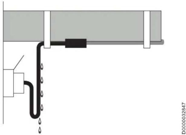
Pure diagram of a pipe connection with a black and white component, no text or symbols present» To prevent condensate from the pipe entering the standard socket, form a "drip loop" with the power cable.
Positioning the thermostat
The thermostat measures the temperature of the pipe and switches the ribbon heater on and off as required.
natural_image
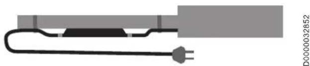
Pure electrical circuit lines without any symbols» Secure the thermostat with a close fit against the pipe at the coldest end of the pipe. Use suitable fixing materials for this purpose, such as fabric tape, aluminium adhesive tape or temperature-resistant cable ties.
Installing the ribbon heater

Note
Secure the ribbon heater to the underside of the pipe.
» Hold the ribbon heater against the pipe parallel to the pipe run, and secure it with aluminium adhesive tape or temperature-resistant cable ties every 20 - 30 cm.
» Cover the ribbon heater with aluminium foil along its entire length to prevent thermal insulation material penetrating between the ribbon heater and the surface that you want to heat.
» If you are using thermal insulation with a sheet metal jacket, use an insulation grommet to protect the ribbon heater from mechanical damage.

Material damage
Make certain that the ribbon heater's supply conductors do not touch each other as this will cause a short circuit.
» Ensure the ribbon heater is appropriately supported in the area next to the electrical connection to prevent any pulling, pushing or twisting forces being applied to the connection.
4.4 Trimming the ribbon heater and terminator

Note
Use a tool that is appropriate for the cross-section of the cable.
» Trim the ribbon heater to the required length.
D0000032838
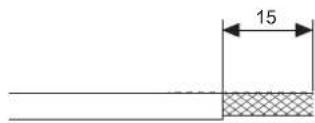
» Strip the end of the ribbon heater to a length of 15 mm.
» Pull back the protective braiding.
D0000032840

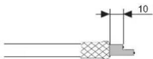
Material damage
To prevent short circuiting, trim one of the two supply conductors to approx. 10 mm.

Note
Do not slide the silicone cap into place without first applying adhesive.
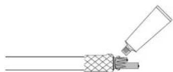
natural_image
Diagram of a cable being inserted into a wire, showing sheath and sheath joint (no text or symbols)D0000032841
» Apply silicone adhesive to the supply conductors in a wave pattern.
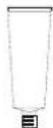
» Check the end cap for integrity.
D0000032842
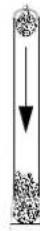
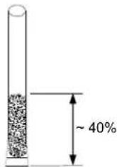
» Drip silicone adhesive into the end cap until the cap is around 40 % full of adhesive.

D0000032848
» Slide the end cap fully onto the end of the ribbon heater.
» Carry out a visual inspection to check that the end cap is correctly positioned on the end of the ribbon heater and is not loose.
4.5 Checks
Once you have finished with the heating circuit, carry out the following checks before fitting the thermal insulation:
» Visually inspect the ribbon heater for any mechanical damage.
» Repair any damage. If the heating circuit is only short, replace the ribbon heater. If the heating circuit is long, cut out the damaged section and use a new section of ribbon.

Note
The insulation resistance must not be below 20 MOhm.
» Measure and log the insulation resistance of the heating circuit between each individual supply conductor and the protective braiding. The test voltage is 1000 V.
» Check the function of the heating circuit.
» Repeat the checks once the thermal insulation has been fitted.
» Identify electrically heated systems with warning labels (e.g. SLHZ stickers) positioned every 5 m.
5. Operation

Note
» Observe local safety regulations.
» Ensure compliance with the permissible operating conditions outlined in the specification table.
6. Maintenance
Self-limiting ribbon heaters are generally maintenance-free. We recommend you arrange for a contractor to carry out a visual inspection and check the insulation resistance on a regular basis.
» When carrying out repairs to heated system parts, protect the ribbon heater from damage.

WARNING Electrocution
Controllers, terminal boxes and female connections may only be opened while the system is isolated from the power supply.
» Recheck the heating circuit once the repair work is complete.
» Damaged heating circuits must be taken out of use.
» Arrange for a contractor to check the thermostats and controls on an annual basis.
7. Installation drawings
7.1 Installation on pipes
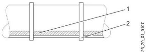
1 Heating ribbon
2 Adhesive tape
» Route and secure the heating cable in parallel with the pipe axis.
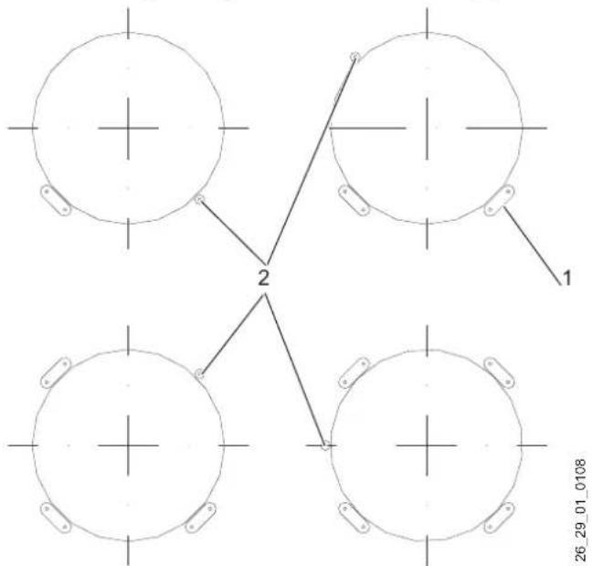
Installing multiple ribbon heaters on pipes
flowchart
graph TD
    A["Top Left Circle"] -->|1| B["Bottom Left Circle"]
    C["Top Right Circle"] -->|1| D["Bottom Right Circle"]
    E["Bottom Left Circle"] -->|2| F["Bottom Right Circle"]
    G["Bottom Right Circle"] -->|2| H["Bottom Left Circle"]
1 Heating ribbon
2 Temperature sensor
Installation on pipe supports
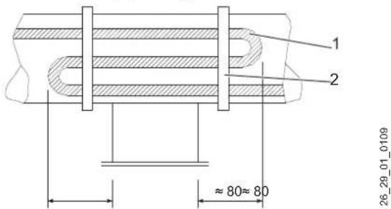
1 Heating ribbon
2 Adhesive tape
7.2 Installation on hydraulic actuators
1 Heating ribbon
2 Adhesive tape
Installation with wire basket on hydraulic actuators
The wire basket allows the ribbon heater to be quickly installed and removed when carrying out maintenance work on hydraulic actuators.
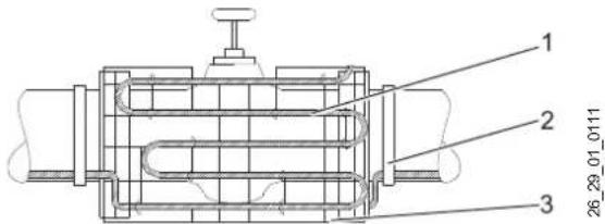
1 Heating ribbon
2 Adhesive tape
3 Wire basket
7.3 Installation on pipe bends
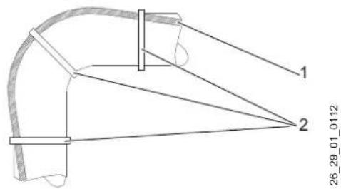
1 Heating ribbon
2 Adhesive tape
7.4 Installation on flanges
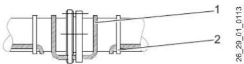
1 Heating ribbon
2 Adhesive tape
7.5 Installation on figure-eight blanks
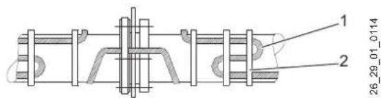
1 Heating ribbon
2 Adhesive tape
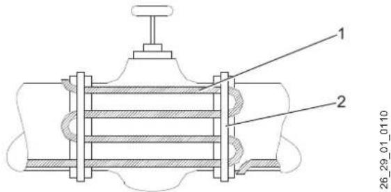
7.6 Installation on valves
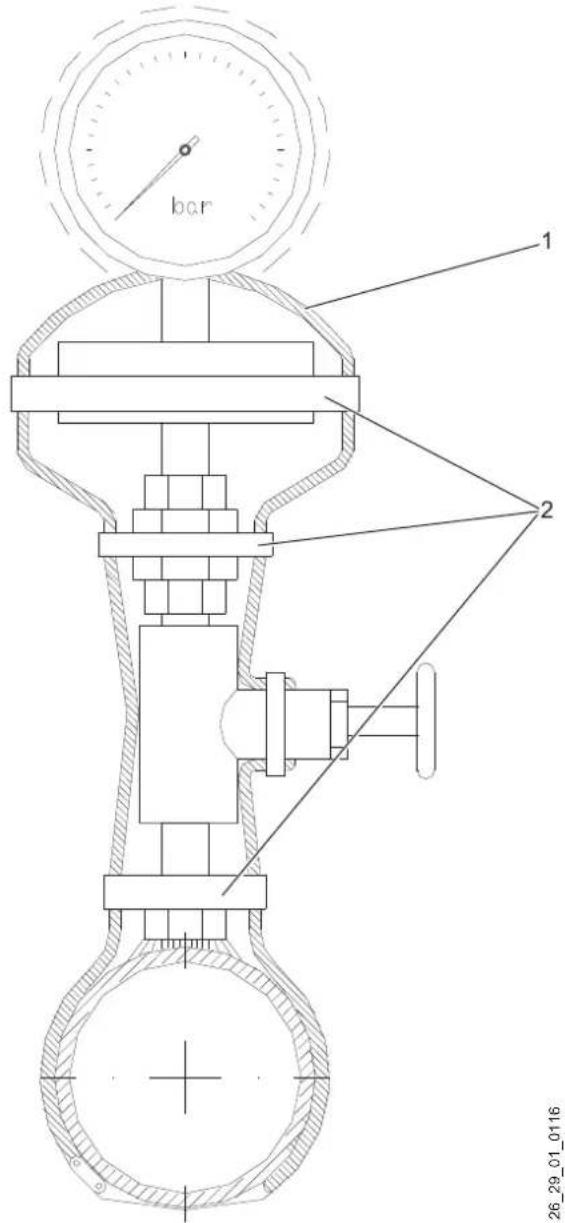
1 Heating ribbon
2 Adhesive tape
7.7 Installation on level indicators
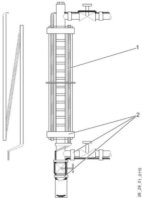
1 Heating ribbon
2 Adhesive tape
» Secure the ribbon heater with self-adhesive aluminium tape.
8. Specification
8.1 Output diagram
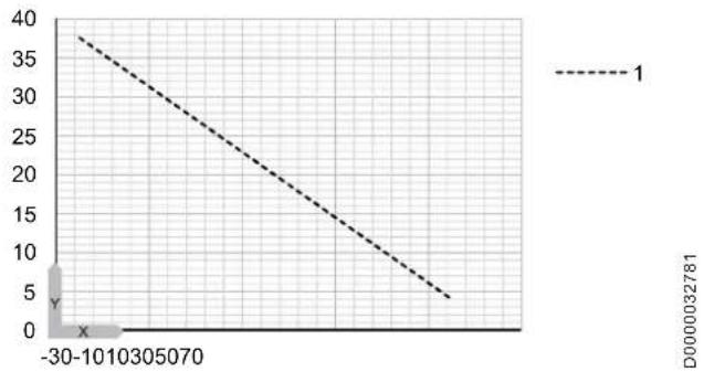
X Pipe temperature [°C]
Y Heating output [W/m]
1 SLH 25
8.2 Specification
| SLH 25/L5 ST SLH 25/L10 ST | SLH 25/L15 ST SLH 25/L20 ST SLH | 25/L25 ST SLH 25/L30 ST | |||||
| 232559 | 232560 | 232561 | 232562 | 232563 | 232564 | ||
| Outputs to EN 14511 | |||||||
| Heating output | W | 125 | 250 | 375 | 500 | 625 | 750 |
| Values | |||||||
| Heat conductor load | W/m | 25 | 25 | 25 | 25 | 25 | 25 |
| Electrical details | |||||||
| Rated voltage | V | 230 | 230 | 230 | 230 | 230 | 230 |
| Power connection | 1/N/PE~230 V | 1/N/PE~230 V | 1/N/PE~230 V | 1/N/PE~230 V | 1/N/PE~230 V | 1/N/PE~230 V | |
| Application limits | |||||||
| Start temperature | °C | 5 | 5 | 5 | 5 | 5 | 5 |
| Shutdown temperature | °C | 13 | 13 | 13 | 13 | 13 | 13 |
| Dimensions | |||||||
| Height | mm | 11 | 11 | 11 | 11 | 11 | 11 |
| Width | mm | 5.6 | 5.6 | 5.6 | 5.6 | 5.6 | 5.6 |
| Length | mm | 7500 | 12500 | 17500 | 22500 | 27500 | 32500 |
| [Heat conductor length] | mm | 5000 | 10000 | 15000 | 20000 | 25000 | 30000 |
| Length of connecting cable | mm | 2500 | 2500 | 2500 | 2500 | 2500 | 2500 |
| Versions | |||||||
| IP rating | IP67 | IP67 | IP67 | IP67 | IP67 | IP67 | |
| Application | Ribbon heater | Ribbon heater | Ribbon heater | Ribbon heater | Ribbon heater | Ribbon heater | |
| Connections | |||||||
| Power cable | Standard plug, connecting cable 2.5 metres long | Standard plug, connecting cable 2.5 metres long | Standard plug, connecting cable 2.5 metres long | Standard plug, connecting cable 2.5 metres long | Standard plug, connecting cable 2.5 metres long | Standard plug, connecting cable 2.5 metres long | |
Warranty
The warranty conditions of our German companies do not apply to appliances acquired outside of Germany. In countries where our subsidiaries sell our products, it is increasingly the case that warranties can only be issued by those subsidiaries. Such warranties are only granted if the subsidiary has issued its own terms of warranty. No other warranty will be granted.
We shall not provide any warranty for appliances acquired in countries where we have no subsidiary to sell our products. This will not affect warranties issued by any importers.
Environment and recycling
We would ask you to help protect the environment. After use, dispose of the various materials in accordance with national regulations.
INSTALACE
natural_image
Pure diagram of a pipe connection with water droplets, no text or symbols presentD0000032847
natural_image
Pure electrical circuit lines without any symbolsD0000032852
natural_image
Diagram of a cable being inserted into a porous material (no text or symbols)D0000032841
26_29_01_0110
26 29 01 0111
26_29_01_0112
26_29_01_0113
26 29 01 0114
natural_image
Pure diagram of a pipe connection with water droplets, no text or symbols presentD0000032847
natural_image
Pure electrical circuit lines without any symbolsnatural_image
Diagram of a cable being inserted into a wire, showing material layers and tip (no text or symbols)D0000032841
Urzhumskaya street 4,
building 2
129343 Moscow
Tel. 0495 7753889
Fax 0495 7753887
Switzerland
STIEBEL ELTRON AG
Industrie West
Gass 8
5242 Lupfig
Tel. 056 4640-500
Fax 056 4640-501