RR Rockstar - Remote control toy MULTIPLEX - Free user manual and instructions
Find the device manual for free RR Rockstar MULTIPLEX in PDF.

User questions about RR Rockstar MULTIPLEX
0 question about this device. Answer the ones you know or ask your own.
Ask a new question about this device
Download the instructions for your Remote control toy in PDF format for free! Find your manual RR Rockstar - MULTIPLEX and take your electronic device back in hand. On this page are published all the documents necessary for the use of your device. RR Rockstar by MULTIPLEX.
USER MANUAL RR Rockstar MULTIPLEX
natural_image
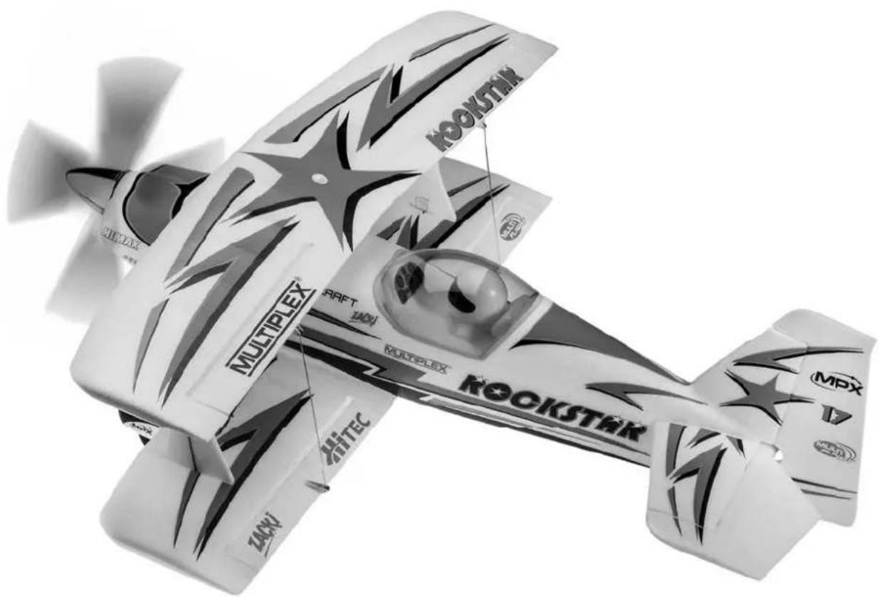
Black-and-white photo of a Star propeller aircraft with visible branding and propellers (no text-heavy elements)D Bauanleitung 2 ... 10
GB Building instructions 11 ... 19
F Notice de construction 20 ... 35
① Instruzioni di montaggio 36 ... 44
ES Instrucciones de montaje 45 ... 53
Abbildungen
Illustrations
Illustrations
Illinstrazioni
liustraciones
Ersatzteile
Replacement parts
Pièces de rechanges
Parti di ricambio
Repuestos
54-56
natural_image
Cross-shaped diagram with diagonal lines and a vehicle silhouette, no text or symbols present
text_image
Prohibition sign with crossed-out lines and icons, featuring a train crossing over water and a cross symbol
natural_image
Diagram of transmission towers crossed out by a diagonal line, no text or symbols present
natural_image
Weather warning symbol with lightning and cloud over rain (no text)
Restrisiken
Inbusschlüssel 3 (KIT)
10er Gabelschlüssel (KIT)
2,5mm Bohrer (KIT)
Vor dem Bau:
This model is NOT A TOY in the usual sense of the term.
By operating the model the owner affirms that he is aware of the content of the operating instructions, especially those sections which concern safety, maintenance, operating restrictions and faults, and is capable of fulfilling these requirements.
This model must not be operated by any child under fourteen years of age. If a person below this age operates the model under the supervision of a competent adult who is acting as the child's guardian within the legal sense of the term, this individual is responsible for the implementation of the information in the OPERATING INSTRUCTIONS.
THE MODEL AND ASSOCIATED ACCESSORIES MUST BE KEPT OUT OF THE REACH OF CHILDREN UNDER THREE YEARS OF AGE! MODELS CONTAIN SMALL DETACHABLE PARTS WHICH MAY BE SWALLOWED BY CHILDREN UNDER THREE YEARS. CHOKING HAZARD!
All the warnings in the OPERATING INSTRUCTIONS must be observed whenever the model is operated. Multiplex Modellsport GmbH & Co. KG accepts no liability for loss or damage or any kind which occurs as a result of incorrect operation or misuse of this product, including the accessories required for its operation. This includes direct, indirect, deliberate and accidental loss and damage, and all forms of consequent damage.
Every safety note in these instructions must always be observed, as all the information contributes to the safe operation of your model. Use your model thoughtfully and cautiously, and it will give you and your spectators many hours of pleasure without constituting a hazard. Failure to operate your model in a responsible manner may result in significant property damage and severe personal injury. You alone bear the responsibility for the implementation of the operating instructions and the safety notes.
Approved usage
The model is approved exclusively for use within the modelling hobby. It is prohibited to use the model for any other purpose than that stated. The operator of the model, and not the manufacturer, is responsible for damage or injury of any kind resulting from non-approved use.
The model may only be operated in conjunction with those accessories which we expressly recommend. The recommended components have undergone thorough testing, are an accurate match to the model, and ensure that it functions safely. If you use other components, or modify the model, you operate it at your own risk, and any claim under guarantee is invalidated.
To minimise the risk when operating the model, please observe the following points:
- The model is guided using a radio control system. No radio control system is immune to radio interference, and such interference may result in loss of control of the model for a period of time. To avoid collisions, you must therefore ensure at all times that there is a wide margin of safety in all directions when operating your model. At the slightest sign of radio interference you must cease operating your model!
- Never operate your model until you have successfully completed a thorough check of the working systems, and carried out a range-check as stipulated in the instructions supplied with your transmitter.
- The model may only be flown in conditions of good visibility. You can avoid being temporarily blinded by not flying towards the sun, or in other difficult light conditions.
- A model must never be operated by a person who is under the influence of alcohol, drugs or medication which have an adverse effect on visual acuity and reaction time.
- Only fly your model in conditions of wind and weather in which you are able to maintain full control of the model. Even when the wind is light, bear in mind that turbulence can form at and around objects which may have an effect on the model.
- Never fly in any location where you may endanger yourself of others, e.g. close to residential areas, overhead cables, open roads and railway lines.
- Never fly towards people or animals. You may think that flying low over other people's heads is proof of your piloting skill, but all it does is place others at unnecessary risk. It is in all our interests that you let other pilots know that this is what you think. Always fly in such a way that you do not endanger yourself or others. Bear in mind that even the best RC system in the world is subject to outside interference. No matter how many years of accident-free flying you have under your belt, you have no idea what will happen in the next minute.
natural_image
Cross-shaped diagram with a vehicle on a road, no text or symbols present
text_image
Prohibition sign with crossed-out lines and symbols, including a train crossing over water and a cross symbol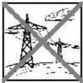
natural_image
Diagram of transmission towers crossed out by a diagonal line, no text or symbols present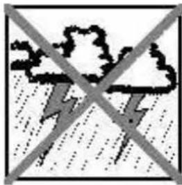
natural_image
Weather warning symbol with lightning and cloud (no text)Residual risks
Even if the model is operated in the correct manner, and you observe all safety aspects, there is always a certain residual risk.
For this reason it is mandatory to take out third-party liability insurance. If you join a club or flying association, insurance is usually available or included in the annual fee. Make sure that your insurance cover is adequate (i.e. that it covers powered model aircraft). Always keep your models and your radio control equipment in perfect order.
The following hazards may occur owing to the model's construction and type:
- Injury caused by the propeller: you must keep well clear of the area around the propeller from the moment that the battery is connected. Please bear in mind that objects in front of the propeller may be sucked into it, and objects behind the propeller may be blown away by it. The model may start moving when the propeller starts to turn. You must therefore position the model in such a way that it cannot move towards other persons if the motor should unexpectedly start running. When you are carrying out adjustment work involving the running motor, you must ensure that the model is always held securely by an assistant.
- Crash caused by pilot error: this can happen even to the best of pilots, so it is essential to fly exclusively in a safe environment; an approved model fl ving site and suitable insurance are basic essentials.
- Crash caused by technical failure or unnoticed damage in transit or in the workshop. A thorough check of the model before every flight is essential. However, you should also take into account at all times that material failures can and do occur. Never fly in a location where your model may damage or injure others.
- Keep within the stated operating limits. Excessively violent flying will weaken the airframe, and may result in sudden material failure, or may cause the model to crash during a subsequent flight due to “creeping” consequent damage.
- Fire hazard caused by electronic failure or malfunction. Store batteries safely, and always observe safety notes which apply to the airborne electronic components, the battery and the battery charger. Protect all electronic equipment from damp. Ensure that the speed controller and battery are adequately cooled.
The instructions which accompany our products must not be reproduced and / or published, in full or in part, in print or any electronic medium, without the express written approval of Multiplex Modellsport GmbH & Co. KG.
MULTIPLEX model kits are subject to constant quality checks throughout the production process, and we sincerely hope that you are completely satisfied with the contents of your kit. However, we would ask you to check all the parts before you start construction, as we cannot exchange components which you have already worked on. If you find any part is not acceptable for any reason, we will readily correct or exchange it. Just send the component to our Model Department. Please be sure to include the purchase receipt and a brief description of the fault.
We are constantly working on improving our models, and for this reason we must reserve the right to change the kit contents in terms of shape or dimensions of parts, technology, materials and fittings, without prior notification. Please understand that we cannot entertain claims against us if the kit contents do not agree in every respect with the instructions and the illustrations.
Caution!
Radio-controlled models, and especially model aircraft, are by no means playthings. Building and operating them safely requires a certain level of technical competence and manual skill, together with discipline and a responsible attitude at the flying field. Errors and carelessness in building and flying the model can result in serious personal injury and damage to property. Since we, as manufacturers, have no control over the construction, maintenance and operation of our products, we are obliged to take this opportunity to point out these hazards and to emphasise your personal responsibility.
Warning:
Like every aeroplane, this model has static limits. Steep dives and senseless manoeuvres inappropriate to the type may result in the loss of the aircraft. Please note: we will not replace the model in such cases. It is your responsibility to approach the airframe's limits gradually. It is designed for the power system recommended in these instructions, but is only capable of withstanding the flight loads if built exactly as described and if it is in an undamaged state.
Recommended equipment:
Zacki ELAPOR 20g VE1 RR+KIT Item number: 852727
Li-BATT FX 4/1 2600 (M6) RR+KIT Item number: 157362
Receiver RX-5 light M-LINK 2,4 GHz RR+KIT Item number: 55808
Drive set ROCKSTAR KIT Item number: 332667
Servo HS-82 MG (4x) KIT Item number: 112088
Extension lead 15 cm (UNI) (2x)
KIT Item number: 85019
Important note
This model is not made of Styrofoam™, and it is not possible to glue the material using white glue, polyurethane or epoxy; these adhesives only produce superficial joints, and simply break away under stress. Please be sure to use medium-viscosity cyano-acrylate glue exclusively, preferably Zacki ELAPOR® # 59 2727, which is optimised specifically for ELAPOR® particle foam. If you se Zacki ELAPOR® there is usually no need for cyano ‘kicker’ or activator. However, if you wish to use a different adhesive which requires the use of activator, please note that these materials are injurious to health, and should always be applied in the open air. Take care when handling all cyano-acrylate adhesives, as they harden in seconds, so don’t get them on your fingers or other parts of the body. We strongly recommend the use of goggles to protect your eyes. Keep the adhesive out of the reach of children! For certain joints it is also possible to use hot-melt adhesive; the instructions indicate where this is the case.
Working with Zacki ELAPOR®
Zacki ELAPOR® has been developed specifi cally for glued joints in our models which consist of moulded ELAPOR® foam parts.
Please observe the following points in order to obtain perfect joints:
- Avoid the use of activator. 'Kicker' significantly weakens the joint. We advise leaving joined parts for 24 hours to obtain maximum strength, particularly when the glued area is large.
- Activator should only be used for temporary, small-area joints ('tacking'). Spray a little activator on one surface, and allow it to air-dry for about thirty seconds.
- To obtain maximum joint strength you should lightly sand the surface with 320-grit abrasive paper before applying glue.
Bent parts - actually don't exist. If you find that a component has taken up a curve, perhaps after being transported, it is easy to straighten again. In this respect ELAPOR® behaves in a similar way to metal: bend the component back slightly beyond the correct position, and the material will then spring back to its proper shape when released, and maintain it. There are limits, however - don't overdo it!
Bent parts - really do exist. If you wish to paint your model, apply MPX Primer # 60 2700 to the surfaces, wiping it on very lightly as if you were cleaning the model. Paint must always be applied thinly and evenly, otherwise the component will warp. Then you really will have bent parts, and they will also be heavy and perhaps even unusable. We have found that matt-fi nish paints produce the best visual effect.
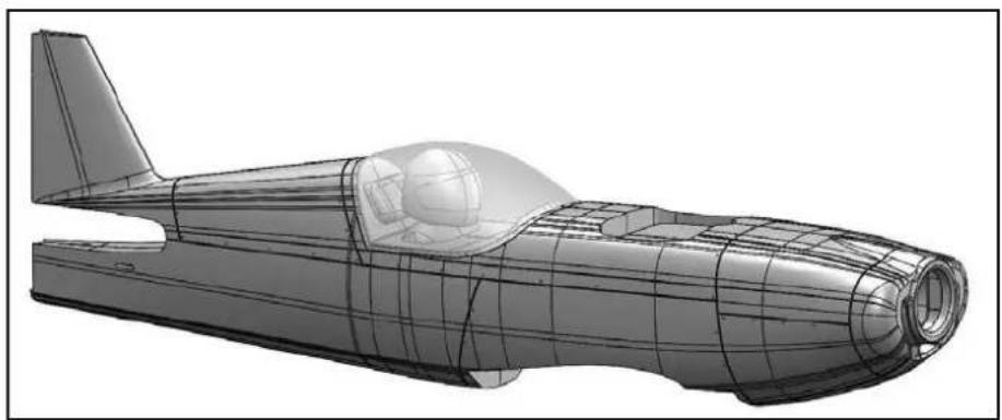
Technical information ROCKSTAR:
Wingspan: 1050 mm
Overall length: 1060 mm
All-up weight: 1800 g
Total surface area: 48 dm²
Wing loading: 38 g/dm²
Channels: 5
RC Functions: rudder, elevator, aileron, motor
Flight time: ca. 7 min (4S \~2600 mAh)
Note: please remove the pictures from the center of the instructions!
Congratulations on your new ROCKSTAR!
You will need the following tools to build the model:
2 x Zacki-Elapor # 85 2727 (KIT) (1xRR)
1 x UHU Por (KIT)
Hot glue gun (KIT)
Medium-sized cross-point screwdriver (KIT)
Medium-sized slot-head screwdriver (KIT)
Balsa knife (KIT)
Pointed-nose pliers (KIT)
1.5 mm A/F allen key (KIT)
3 mm A/F allen key (KIT)
10 mm A/F open-ended spanner (KIT)
2.5 mm drill (KIT)
Before starting construction:
Please check that all the parts are present, referring to the Parts List on page 18+19 (Figs. 01 & 02).
1. Assembling the fuselage (KIT)
Clip together the two parts 33 and 34 which form the spread-er plate for the wing retaining bolt, and glue the joint with Zacki. ! Caution ! Watch out for excess glue squirting out when the parts are joined. Glue the Canopy Lock clip 31, the cabane socket 28 and the wing bolt spreader plate in the right-hand fuselage shell 5. Glue the two rudder hinge pin supports 44 in the slots in the right-hand fi n shell. At the same time glue the M5 nut support 39 and the tailwheel bracket 40 in place.
Figs. 03 + 04
Slip a length of spring steel wire 73 through the snake outer sleeve 74, and lay it in the right-hand fuselage shell as shown; the snake outer should project about 30 mm from the tail end of the fuselage. Glue it in place permanently.
Figs. 05 - 07
Now glue the pre-assembled M-Frame 27 in the right-hand fuselage shell 5.
Fig. 08
Working in a similar manner, glue the following parts in the left-hand fuselage shell 4: the Canopy Lock clip 31 and the cabane socket 28. A second spring steel rod 73 should now be slipped into a snake outer sleeve 74, and fitted in the left-hand fuselage shell; this should also project at the tail end by about 30 mm.
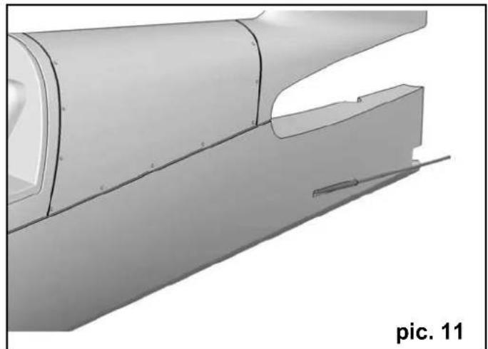
Figs. 09 - 11
Now offer up the two fuselage shells to each other dry (WITHOUT glue), and check that they fi t together snugly at all points. When you are confi dent that everything matches up correctly, apply glue to the joint surfaces, fi t the two shel together, and check that they are accurately aligned.
Figs. 12 + 13
With this step complete, it is time to paint the dummy pilot in the colour scheme of your choice.
Please note that dark areas under the canopy may heat up strongly if subjected to direct sunshine. If this should happen, the ELAPOR foam may swell and bubble!
Apply the instrument panel sticker (decal sheet) to the moulded-in binnacle inside the cockpit. When you are satisfi ed with the appearance of your cockpit, glue the canopy 26 to the fuselage using UHU Por.
Fig. 14
Locate the four magnets 58 which retain the cowl 6, and glue them in the appropriate recesses at the front of the fuselage.
Fig. 15
Hold the rudder servo in your hand and centre it from the transmitter. Drill out the outermost hole in the servo output arm using a 2.5 mm ∅ bit. Fit the output arm on the servo shaft as shown in Fig. 16, and secure it with the output screw. Mount the swivel pushrod connector 54 in the outer hole in the output arm, securing it with the M2 self-locking nut 56. Fit an M3 grubscrew 55 in the open end of the pushrod connector barrel.
Place the servo in the opening in the left-hand side of the M-Frame, and secure it with the retaining screws supplied with the servo.
Fig. 16
Repeat the procedure with the elevator servo, with this exception: fi t the output arm on the servo facing the opposite direction. Install the elevator servo in the right-hand opening in the M-Frame.
Fig. 17
Glue the four remaining magnets 58 in the appropriate recesses in the cowl 6.
! CAUTION !: Ensure that the pairs of magnets attract, rather than repel!
Fig. 18
Glue the two Canopy Lock lugs 32 in the slots in the fuselage hatch 7.
Fig. 19
2. Assembling the undercarriage (KIT+RR)
Glue the left-hand wheel spat holder 45 in the inboard left-hand wheel spat shell 18, then glue the outboard wheel spat shell 19 to the inboard shell. Repeat the procedure with the right-hand wheel spat (parts 20, 46 and 21).
Figs. 20 + 21
Place one lightweight wheel 67 in the left-hand wheel spat, then slip the wheel axle (M4 x 40 mm machine screw) 64 through the spat and wheel. Fit an M4 nut 66 loosely on the end of the screw. Fit a washer 65 on the screw, then slip it through the hole in the left-hand leg of the undercarriage unit 62 before securing it with a further washer 65 and an M4 self-locking nut 63.
Caution: the straight edge of the undercarriage unit is "forward"! Fig. 47 clearly shows the correct orientation of the undercarriage. Repeat the procedure with the right-hand wheel spat, and attach it to the right-hand leg of the undercarriage unit in the same way.
Fig. 22
The next step is to glue the undercarriage fairing 22 to the metal undercarriage unit with a drop of Zacki, but first check the correct position of the fairing by holding the undercarriage on the fuselage. The completed undercarriage unit can now be fixed to the fuselage using four M4 x 12 mm socket-head screws. Figs. 23 + 24
Fit the tailwheel 70 on the axle of the tailwheel unit, and secure it with the collet 71.
Fig. 25
3. Tail panels (KIT+RR)
Glue four hinge pin supports 44 in the bottom half of the tailplane 13. Glue the sleeve 38 for the tailplane retainer screw between the inboard hinge pin supports as shown, then glue the bottom tailplane shell 13 to the top tailplane shell 12.
Fig. 26
Glue the recessed hinge pin units 43 in the elevator 14. Glue the 3 mm ∅ carbon fi bre tube 72 in the long slot. Close the elevator by gluing the cover 15 in place, followed by the elevator horn 49.
Fig. 27
The hinges can now be clipped together to attach the elevator to the tailplane. Slide the tailplane assembly into the slot in the fuselage, and secure it by ft tting the plastic M5 x 60 retaining screw 48 from the underside.
Figs. 28 + 29
Attach a swivel pushrod connector 53 to the elevator horn and slip the spring steel pushrod through the hole in the barrel. Set the elevator to neutral (centre), then tighten the M3 grubscrew 55 in the barrel to clamp the pushrod in place
Fig. 30
Glue two hinge pin units 43 and the rudder horn 42 in the rudder 16, then close the rudder by gluing the cover 17 in place. The completed rudder can now also be attached to the fi n: fi rst engage the spigot which forms the bottom fi n hinge, then clip the two upper hinges together.
Figs. 31 - 33
Mount a swivel pushrod connector 53 on the rudder horn as described for the elevator, and clamp the spring steel pushrod in the barrel using an M3 grubscrew 55.
Fig. 34
4. Installing the motor (KIT+RR)
Attach the motor to the aluminium mount 59 using the four screws supplied, not forgetting to apply a drop of medium-strength thread-lock fluid to each screw! Now install the motor in the fuselage using the stand-off pillars 61 and four M4 x 65 mm machine screws 60 and washers 65.
Fig. 35
Fit the propeller driver 86 on the motor shaft together with the taper collet 87, the spinner backplate 85, the propeller 84, a 6 mm I.D. washer 83 and the M6 nut 82. Tighten the retaining nut lightly, then rotate the propeller until it rests against the spinner backplate's integral bosses. Hold the propeller in this position while you tighten the retaining nut fully.
Fit the spinner cap 81 over this assembly, and fi x it to the spinner backplate using two 3 x 16 mm screws 81.
Fig. 36
5. Completing the wings (KIT+RR)
The first step is to assemble the cabane for the top wing: glue the cabane struts 23 and 24 and the wing bolt sleeve 35 to the cabane core 25. Glue the left and right cabane retainers 29 and 30 in the underside of the cover, followed by the 3 x 1 x 100 mm CFRP strip 78.
Fig. 37
Glue the strut clips 36 to both ends of the two wing struts 10 and 11, and glue a 3 x 1 x 190 mm CFRP strip 77 on the inboard face of each strut. Take care that no glue runs into the strut clips.
Figs. 38 + 39
Glue the tubular spar 79 in the channel in the underside of the top wing 8, and a socket 37 for the strut clips on each side. You will find recesses in the ailerons for the aileron link rod supports 50; glue these in place on both sides.
Fig. 40
Centre the aileron servos from your transmitter before screwing the output arms to the output shafts. The servos should be glued in the openings in the bottom wing 9, applying just a little hot-melt glue to the servo mounting lugs. Deploy the servo leads in the cable ducts, and apply adhesive tape over the open slots to seal them. Glue a horn 49 and an aileron link rod support 50 in each aileron. Locate the hole in the central wing fairing for the wing bolt, and glue the sleeve 35 in it.
Fig. 41
Connect the pre-formed end of the aileron pushrods 75 to the aileron servos, and connect them to the aileron horns in the usual manner, using the swivel pushrod connectors 53 and M3 grubscrews 55.
Fig. 42
Carefully glue the cabane assembly to the underside of the top wing as shown, ensuring that it fi ts the correct way round!
Fig. 43
6. Installing the receiving system (KIT+RR)
Connect all the servo leads to the receiver, and program the model memory to give the recommended control surface travels. Unless you have changed the channel assignment -at the transmitter, the standard sequence for MULTIPLEX radio systems is as follows:
- L.H. aileron
- Elevator
- Rudder
- Throttle
- R.H. aileron
Fix the receiver to the bottom of the M-Frame using hook-and-loop tape. A few drops of Zacki will ensure that the tape adheres firmly to the wood. The receiver can also be secured with a cable-tie.
7. Final airframe assembly (KIT+RR)
The first step is to attach the bottom wing to the fuselage: turn the fuselage onto its back, then guide the leading edge of the wing into the corner between the undercarriage and the undercarriage fairing. Connect the aileron lead to the receiver, then fold the wing's trailing edge down onto the wing saddle, and engage the locating lug in the fuselage. The wing can now be finally positioned, and fixed to the fuselage using a single M5 x 35 mm plastic screw 47. Turn the aircraft right side up so that it stands on its undercarriage, and clip the wing struts to the bottom wing on each side. The top wing and cabane can now be fitted on the fuselage, and the top end of the wing struts clipped in place. The final step is to secure the top wing with a second M5 x 35 mm plastic screw 47.
Fig. 44
Two metal rods 76 are used to link the top and bottom ailerons: fi rst attach swivel pushrod connectors to all four aileron link rod supports. Note that the red parts 51 belong on the left-hand side, and the green parts 52 on the right-hand side. Centre the ailerons from the transmitter before attaching one aileron link rod at the top using an M3 grubscrew 55. Clamp the link rod at the bottom with a further M3 grubscrew, taking care to keep both ailerons centred. Repeat the procedure on the other side.
Figs. 45 + 46
When dismantling the model, simply unclip the swivel pushrod connector barrels from their supports; this method maintains the correct alignment of the ailerons relative to each other. The colour of the connectors makes it easy to see the side to which they belong:
$$ \begin{array}{l} \text { RED = left } \ \text { GREEN = right } \end{array} $$
8. Balancing (KIT+RR)
First glue the two ballast weights 91 in the motor compartment with Zacki; check that the cowl can still be closed. Slide the flight battery into the battery tray, and adjust its position until the model balances at the recommended Centre of Gravity (100 mm back from the top wing leading edge, measured adjacent to the fuselage). Fix the battery in place using the strips of hook-and-loop tape 88 and 89 and the hook-and-loop strap 90. To ensure a strong joint, we recommend applying a few drops of Zacki to the hook-and-loop tape where it makes contact with the bottom of the fuselage.
9. Recommended control surface travels
for the classic aerobatic schedule:
$$ \begin{array}{l} \text {Rudder:} \quad 40 \mathrm{mmright/left,} 60 \% \text {EXPO} \ \text{Elevator:} \quad 40 \text{ mm up, } 40 \text{ mm down, } 70\% \ \text { EXPO } \ \text{Ailerons:} \quad 17 \text{ mm up, } 17 \text{ mm down, } 40\% \ \text { EXPO } \ \end{array} $$
Mixer (linear): 3,5mm aileron to rudder, opposite travel →i.e.: ailerons defl ect left by 3,5mm at full right-rudder
For 3D aerobatics:
Rudder: 65 mm right / left, 60% EXPO
Elevator: 55 mm up / 55 mm down, 70%
Ailerons: 22 mm up / 22 mm down, 50%
Mixer (linear): 3,5mm aileron to rudder, opposite travel
→i.e.: ailerons defl ect left by
3,5mm at full right-rudder
4mm elevator to rudder
→i.e.: elevator defl ects up by
4mm at full right /left -rudder
No. Kit RR Description Material Dimensions
| 1 | 1 | 1 | KIT building instructions Paper 80 g/m2 DIN-A4 | ||
| 2 | 1 | 1 | Model complaints form Paper 80 g/m2 DIN-A4 | ||
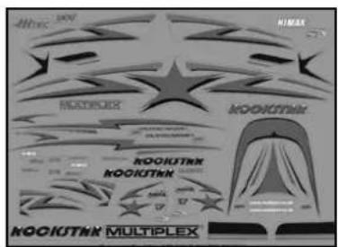
| 3 | 1 | 1 | Decal sheet Printed self-adhesive fi lm 700 x 1000mm | ||
| 4 | 1 | 1 | L.H. fuselage shell | Moulded Elapor foam | Ready made |
| 5 | 1 | 1 | R.H. fuselage shell | Moulded Elapor foam | Ready made |
| 6 | 1 | 1 | Cowl | Moulded Elapor foam | Ready made |
| 7 | 1 | 1 | Fuselage hatch | Moulded Elapor foam | Ready made |
| 8 | 1 | 1 | Top wing | Moulded Elapor foam | Ready made |
| 9 | 1 | 1 | Bottom wing Moulded Elapor foam | Ready made | |
| 10 | 1 | 1 | L.H. wing strut | Moulded Elapor foam | Ready made |
| 11 | 1 | 1 | R.H. wing strut | Moulded Elapor foam | Ready made |
| 12 | 1 | 1 | Tailplane, top | Moulded Elapor foam | Ready made |
| 13 | 1 | 1 | Tailplane, bottom | Moulded Elapor foam | Ready made |
| 14 | 1 | 1 | Elevator | Moulded Elapor foam | Ready made |
| 15 | 1 | 1 | Elevator cover | Moulded Elapor foam | Ready made |
| 16 | 1 | 1 | Rudder | Moulded Elapor foam | Ready made |
| 17 | 1 | 1 | Rudder cover | Moulded Elapor foam | Ready made |
| 18 | 1 | 1 | L.H. inboard wheel spat shell | Moulded Elapor foam | Ready made |
| 19 | 1 | 1 | L.H. outboard wheel spat shell | Moulded Elapor foam | Ready made |
| 20 | 1 | 1 | R.H. inboard wheel spat shell | Moulded Elapor foam | Ready made |
| 21 | 1 | 1 | R.H. outboard wheel spat shell | Moulded Elapor foam | Ready made |
| 22 | 1 | 1 | Central undercarriage fairing | Moulded Elapor foam | Ready made |
| 23 | 1 | 1 | L.H. cabane strut | Moulded Elapor foam | Ready made |
| 24 | 1 | 1 | R.H. cabane strut | Moulded Elapor foam | Ready made |
| 25 | 1 | 1 | Cabane core | Moulded Elapor foam | Ready made |
| 26 | 1 | 1 | Canopy | Vac.-moulded plastic Ready made | |
| 27 | 1 | 1 | Tornado motor dome, complete | Lime plywood, 3 mm | Ready made |
| 28 | 4 | 4 | Cabane socket | Lime plywood, 3 mm | Ready made |
| 29 | 1 | 1 | L.H. cabane retainer | Inj.-moulded plastic | Ready made |
| 30 | 1 | 1 | R.H. cabane retainer | Inj.-moulded plastic | Ready made |
| 31 | 2 | 2 | Canopy Lock clip | Inj.-moulded plastic | Ready made |
| 32 | 2 | 2 | Canopy Lock lug | Inj.-moulded plastic | Ready made |
| 33 | 2 | 2 | Wing bolt spreader plate A | Inj.-moulded plastic | Ready made,M5 |
| 34 | 2 | 2 | Wing bolt spreader plate B | Inj.-moulded plastic | Ready made,M5 |
| 35 | 2 | 2 | Wing bolt sleeve | Inj.-moulded plastic | Ready made |
| 36 | 4 | 4 | Wing strut clip | Inj.-moulded plastic | Ready made |
| 37 | 4 | 4 | Wing strut clip socket | Inj.-moulded plastic | Ready made |
| 38 | 1 | 1 | Tailplane retainer screw sleeve | Inj.-moulded plastic | Ready made |
| 39 | 1 | 1 | M5 nut support | Inj.-moulded plastic | Ready made |
| 40 | 1 | 1 | Tailwheel bracket | Inj.-moulded plastic | Ready made |
| 41 | 1 | 1 | Tailwheel bracket clamp | Inj.-moulded plastic | Ready made |
| 42 | 1 | 1 | Rudder horn | Inj.-moulded plastic | Ready made |
| 43 | 6 | 6 | Recessed hinge pin unit | Inj.-moulded plastic | Ready made |
| 44 | 6 | 6 | Recessed hinge pin support | Inj.-moulded plastic | Ready made |
| 45 | 1 | 1 | L.H. wheel spat holder | Inj.-moulded plastic | Ready made |
| 46 | 1 | 1 | R.H. wheel spat holder | Inj.-moulded plastic | Ready made |
| 47 | 2 | 2 | Plastic cheesehead screw | Plastic | M5 x 35mm |
| 48 | 1 | 1 | Plastic cheesehead screw | Nylon | M5 x 60mm |
No. Kit RR Description Material Dimensions
| 49 | 3 | 3 | „Twin“ control surface horn Inj.-moulded plastic Ready made | |
| 50 | 4 | 4 | Aileron link rod barrel support Inj.-moulded plastic Ready made | |
| 51 | 2 | 2 | Swivel barrel RED Metal 6 ∅ x 8mm | |
| 52 | 2 | 2 | Swivel barrel GREEN Metal 6 ∅ x 8mm | |
| 53 | 4 | 4 | Swivel barrel CLEAR Metal 6 ∅ x 8mm | |
| 54 | 2 | 2 | Swivel barrel CLEAR Metal 6 ∅ x 8mm | |
| 55 | 11 | 11 | Socket-head grubscrew Metal M3 x 3mm | |
| 56 | 2 | 2 | Self-locking nut Metal M2 | |
| 57 | 1 | 1 | Nut Metal M5 | |
| 58 | 8 | 8 | Magnet Neodymium 5 x 2 x 10mm | |
| 59 | 1 | 1 | Aluminium motor mount Aluminium Ready made | |
| 60 | 4 | 4 | Socket-head screw, motor bulkhead mounting, Metal M4 x 65mm | |
| 61 | 4 | 4 | Motor bulkhead stand-off pillar Aluminium Ready made | |
| 62 | 1 | 1 | Main undercarriage unit Aluminium F38 Ready made | |
| 63 | 2 | 2 | Self-locking nut Metal M4 | |
| 64 | 2 | 2 | Machine screw for wheel axle Metal M4 x 40mm | |
| 65 | 8 | 8 | Washer Metal 4mm I.D. | |
| 66 | 2 | 2 | Wheel axle retaining nut Metal M4 | |
| 67 | 2 | 2 | Lightweight wheel Plastic 73mm ∅ | |
| 68 | 4 | 4 | Socket-head screw Metal M4 x 12mm | |
| 69 | 1 | 1 | Tailwheel unit Spring steel 1.5∅ x 210mm | |
| 70 | 1 | 1 | Lightweight tailwheel Foam rubber 26mm ∅ | |
| 71 | 1 | 1 | Tailwheel collet Metal 2mm I.D. | |
| 72 | 1 | 1 | CFRP tube, 3 ∅ Metal 3 ∅ x 370mm | |
| 73 | 2 | 2 | Spring steel wire Metal 1.2∅ x 740mm | |
| 74 | 2 | 2 | Snake outer sleeve Plastic 3 ∅ x 590mm | |
| 75 | 2 | 2 | Pre-formed aileron pushrod Metal (1.4310) 1.3 ∅ x 70mm | |
| 76 | 2 | 2 | Aileron link rod Metal (1.4310) 1.5∅ x 210mm | |
| 77 | 2 | 2 | CFRP strip, wing strut CFRP 3x1 x 190mm | |
| 78 | 1 | 1 | CFRP strip, central strut CFRP 3x1 x 100mm | |
| 79 | 1 | 1 | Tubular spar GRP tube 8 ∅ x 800mm | |
| 80 | 2 | 2 | Spinner retaining screw Metal 3 x 16mm | |
| 81 | 1 | 1 | Spinner cap Inj.-moulded plastic 62mm ∅ | |
| 82 | 1 | 1 | Nut Metal M6 | |
| 83 | 1 | 1 | Washer Metal 6mm I.D. | |
| 84 | 1 | 1 | Propeller Inj.-moulded plastic 14 x 7" | |
| 85 | 1 | 1 | Spinner backplate Inj.-moulded plastic 62mm ∅ | |
| 86 | 1 | 1 | Propeller driver Metal Ready made | |
| 87 | 1 | 1 | Taper collet Metal Ready made | |
| 88 | 3 | 3 | Hook-and-loop tape, hook Plastic 25 x 60mm | |
| 89 | 3 | 3 | Hook-and-loop tape, loop Plastic 25 x 60mm | |
| 90 | 1 | 1 | Hook-and-loop strap Plastic 25 x 200mm | |
| 91 | 2 | 2 | Ballast weight Metal 25 x 19x5mm | |
| 92 | 0 | 4 | Motor mount screws Metal 3 x 8mm | |
| 93 | 0 | 1 | Motor Himax 4220-620 | |
| 94 | 0 | 4 | Servos HiTec HS-82MG | |
| 95 | 0 | 1 | ESC MULTIcont BL-60 SD |
natural_image
Technical line drawing of a mechanical assembly with no visible text or symbols
natural_image
3D mechanical component diagram showing internal structural elements (no text or symbols)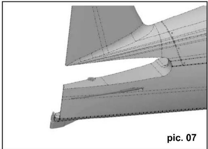
natural_image
Technical line drawing of a mechanical component with no visible text or symbols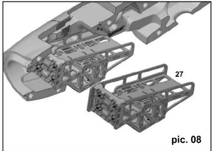
natural_image
3D mechanical assembly diagram showing two views of a vehicle chassis with internal components (no text or symbols)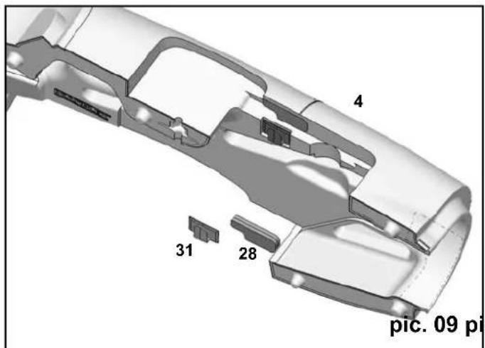
text_image
4 31 28 pic. 09 pi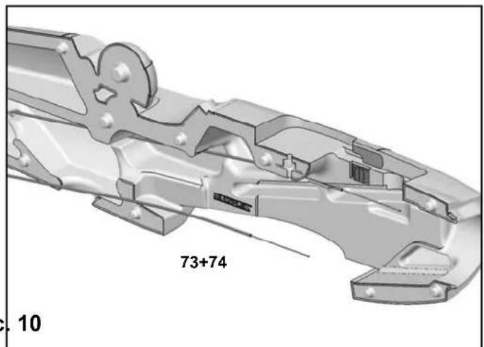
text_image
73+74 1005
natural_image
3D CAD model of a mechanical component with cutaway view, labeled 'pic. 11' (no other text or symbols)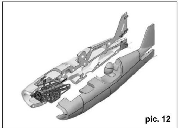
natural_image
3D cutaway diagram of an aircraft fuselage showing internal components and structural details (no text or symbols)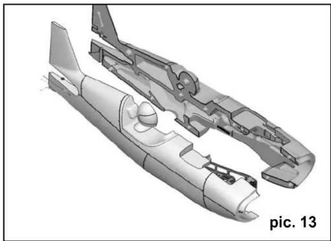
natural_image
3D cutaway diagram of a mechanical component with no visible text or symbols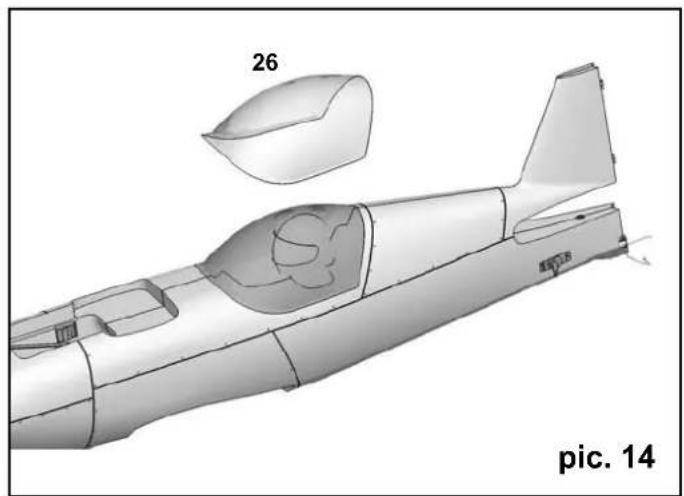
natural_image
Technical line drawing of a propeller aircraft with labeled parts (no text or symbols on the diagram itself)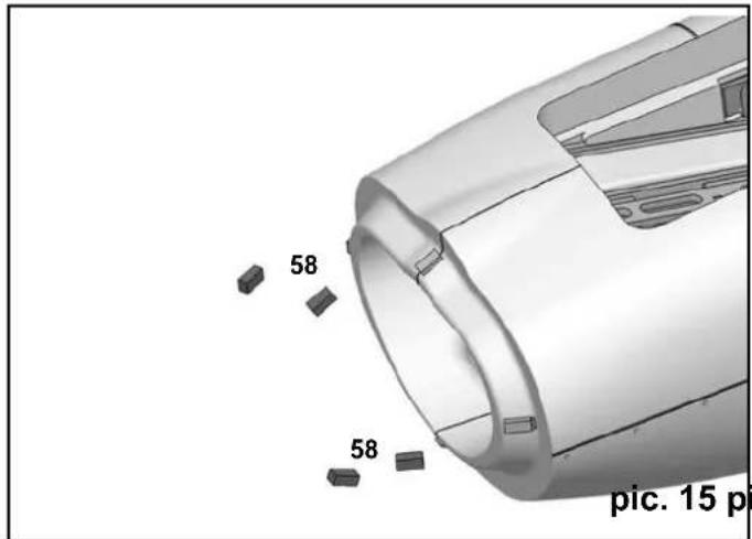
text_image
58 58 pic. 15 p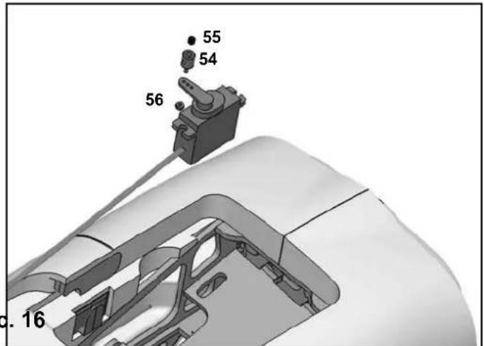
text_image
55 54 56 16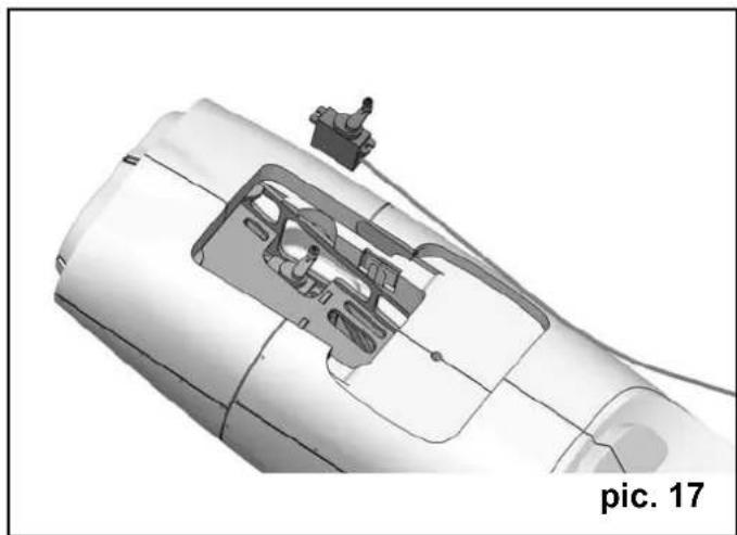
natural_image
Technical illustration of a mechanical component with internal components and a labeled section 'pic. 17' (no readable text or symbols beyond label)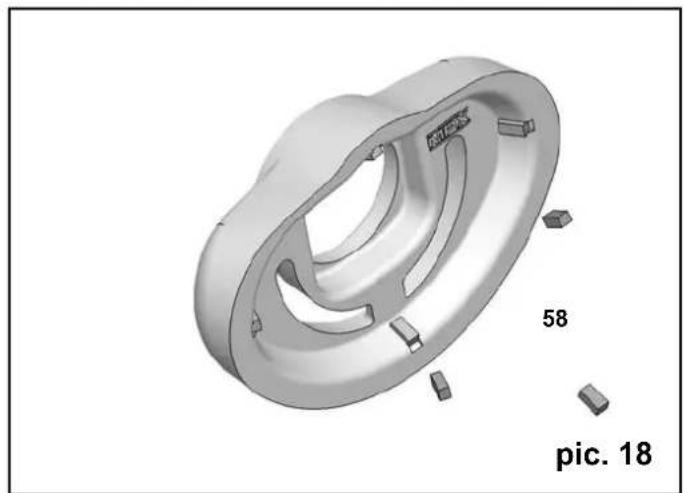
natural_image
3D rendered mechanical component with cutouts and labeled parts (no readable text or symbols)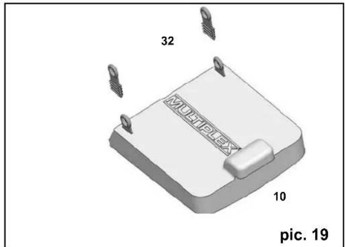
text_image
32 MULTIPLEX 10 pic. 19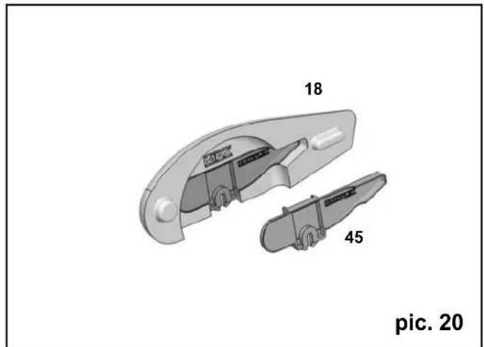
text_image
18 MCK 45 pic. 20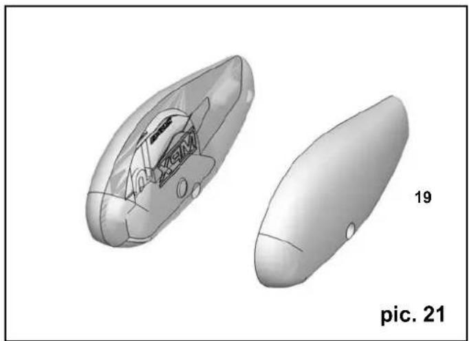
natural_image
3D rendered diagram of two views of an elongated object, one cutaway showing internal structure and the other flat (no text or symbols)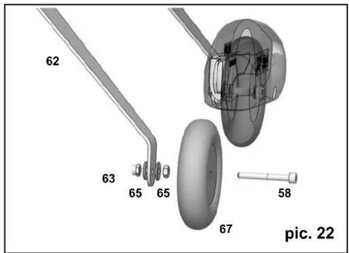
text_image
62 63 65 65 67 58 pic. 22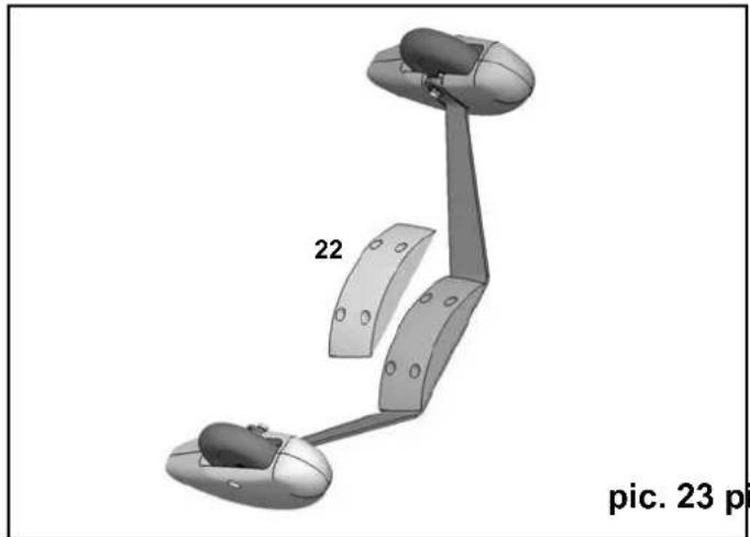
natural_image
3D mechanical assembly diagram with labeled parts (22 and pic. 23 p), no readable text or symbols beyond labels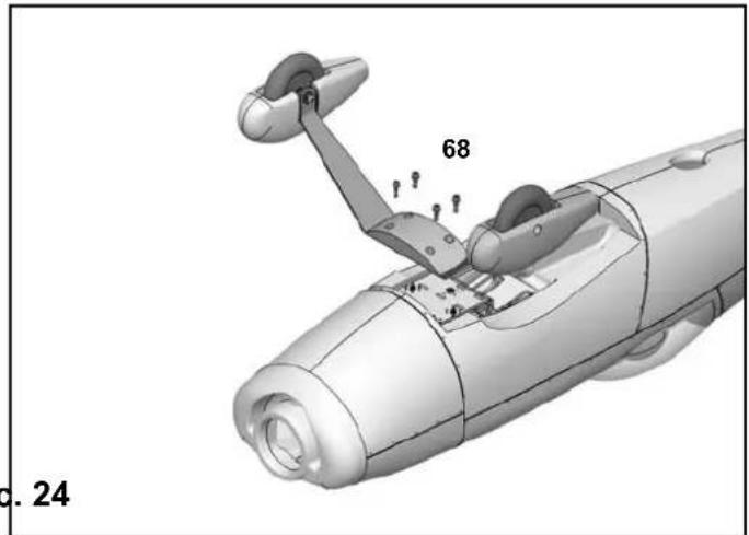
text_image
68 24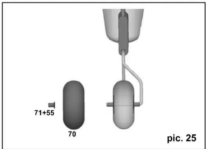
text_image
71+55 70 pic. 25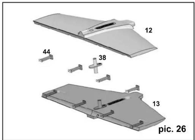
text_image
12 44 38 13 pic. 26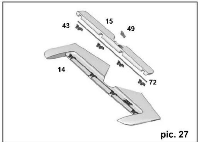
text_image
43 15 49 14 72 pic. 27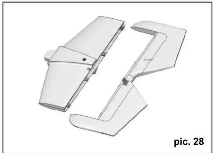
natural_image
3D model of a white plastic mechanical component with no visible text or symbols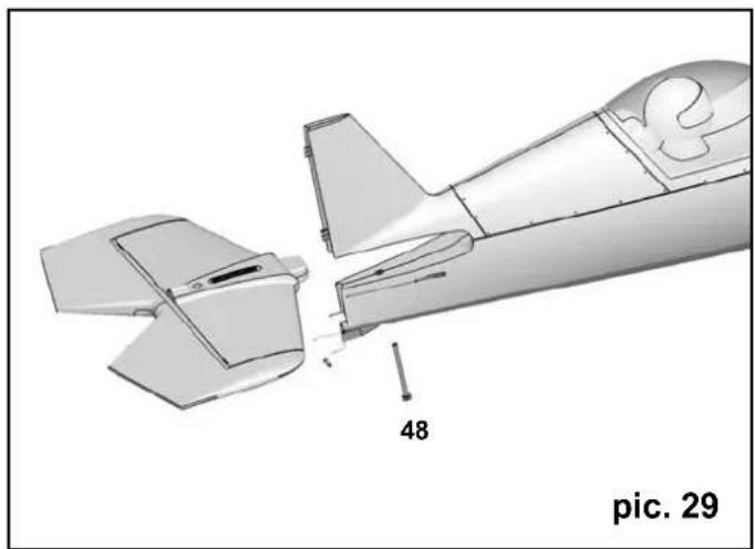
natural_image
Technical illustration of a mechanical aircraft with cutaway sections and labeled part (48), no readable text or symbols beyond labels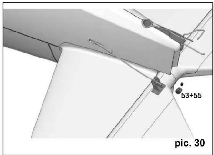
text_image
53+55 pic. 30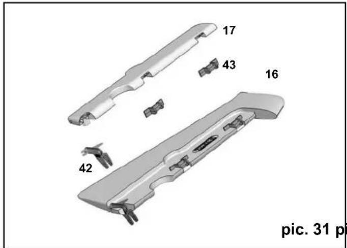
text_image
17 43 16 42 pic. 31 p
natural_image
Technical illustration of an aircraft wing assembly (no text or symbols visible)
natural_image
3D mechanical component diagram with no visible text or symbols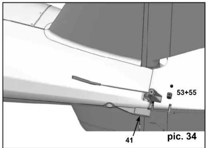
text_image
53+55 41 pic. 34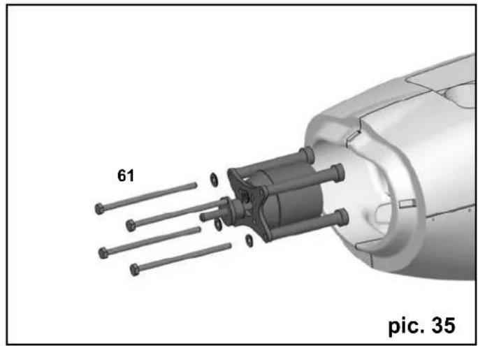
natural_image
3D mechanical assembly diagram showing internal components with pins, labeled 'pic. 35' (no text or symbols beyond labels)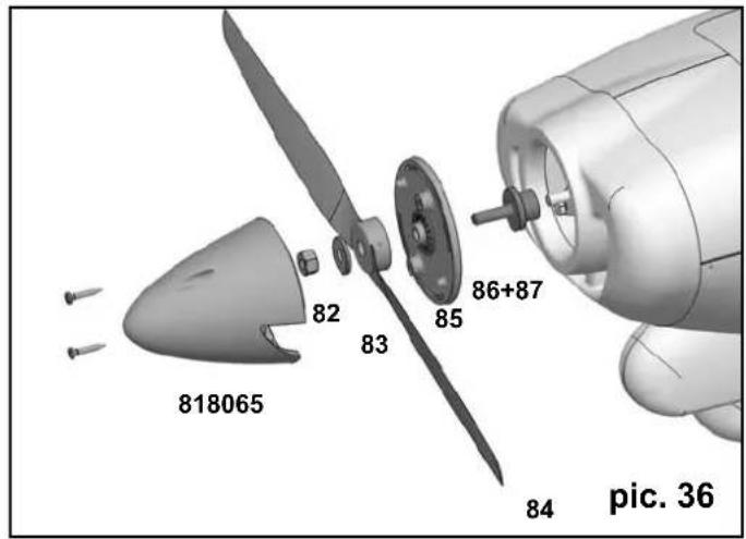
text_image
818065 82 83 85 86+87 84 pic. 36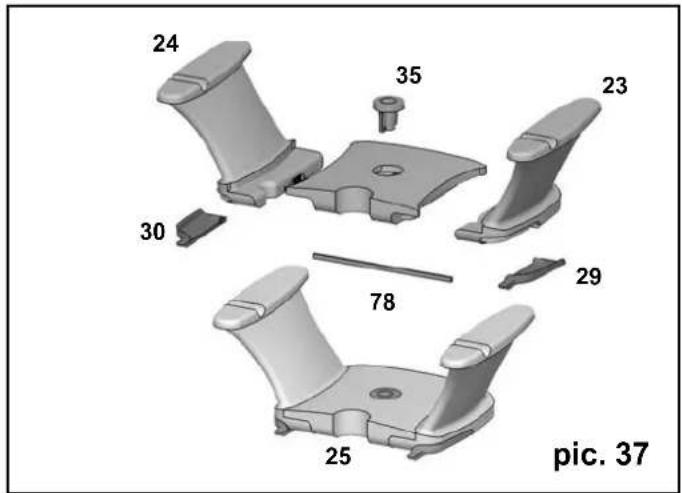
text_image
24 35 23 30 78 29 25 pic. 37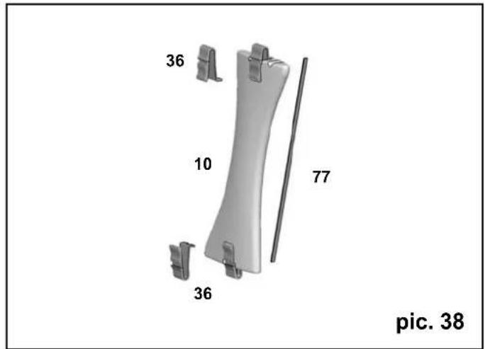
text_image
36 10 77 36 pic. 38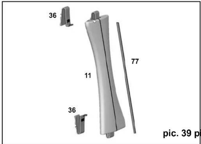
text_image
36 11 77 36 pic. 39 p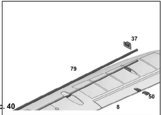
text_image
37 79 40 8 50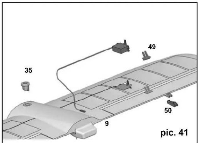
text_image
35 49 50 9 pic. 41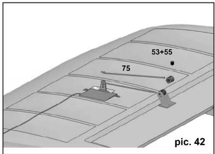
text_image
53+55 75 pic. 42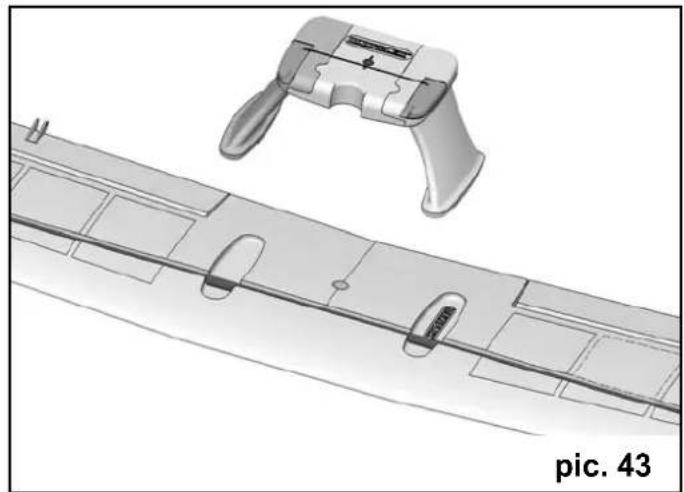
natural_image
3D CAD model of a mechanical component with a bracket and internal slots, labeled 'pic. 43' (no text or symbols on the diagram itself)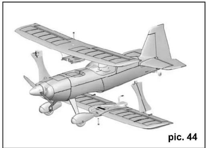
natural_image
3D model of an early propeller aircraft in flight, showing wing and fuselage details (no text or symbols on the aircraft itself)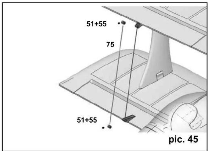
text_image
51+55 75 51+55 pic. 45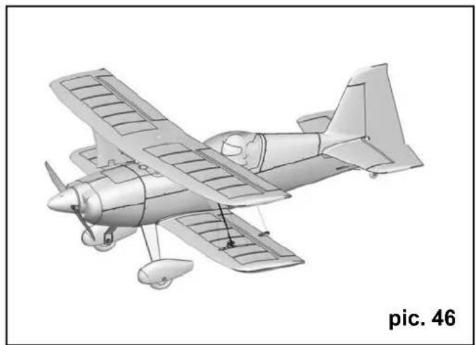
natural_image
Line drawing of a small propeller airplane in flight, showing aerodynamic components and fuselage (no text or symbols on the aircraft itself)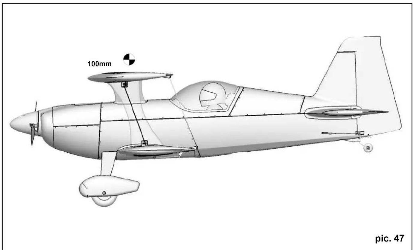
natural_image
Technical line drawing of a propeller airplane with propellers and control panels, labeled 'pic. 47' (no text or symbols on the diagram itself)natural_image
Black-and-white illustration of a car crossing a road with diagonal lines (no text or symbols)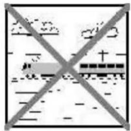
text_image
Prohibition sign with crossed-out lines and symbolic imagery, likely for transportation or infrastructure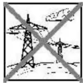
natural_image
Symbolic illustration of transmission towers crossed out, representing power lines or transmission (no text present)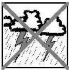
natural_image
Weather warning symbol with lightning and raindrops crossed out (no text)Rischi residui
natural_image
Technical line drawing of a two-engine aircraft with internal components and exploded view (no text or symbols)# 22 4330
RR-Rumpf mit Dekor
RR fuselage with decals
natural_image
3D wireframe model of a jet aircraft showing internal structural components (no text or symbols)224422 # 22 4402
Cowl / fuselage hatch
natural_image
3D CAD model of a mechanical pump or impeller component with internal channels and mounting holes (no text or symbols)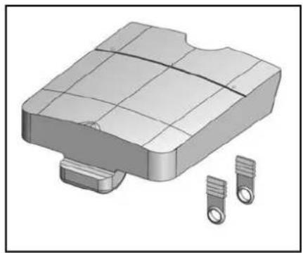
natural_image
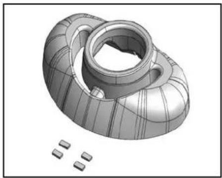
3D rendered mechanical component with internal grid structure and two cylindrical pins (no text or symbols)22 44404 # 22 4426
Kabinenhaube / Spinner
Canopy / spinner

natural_image
Smooth, curved 3D object with smooth surface and tapered ends (no text or symbols)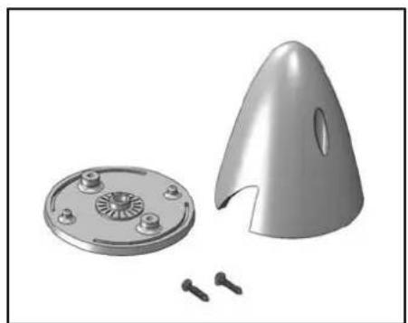
natural_image
3D rendered mechanical parts including a circular base with screw holes and a conical housing, alongside several small pins (no text or symbols visible)# 22 4412
# 22 4414
natural_image
Collection of mechanical parts including bolts, rings, and blocks (no text or symbols visible)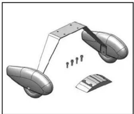
natural_image
3D model of a mechanical assembly with multiple components and mounting holes (no text or symbols visible)# 22 4406 # 22 4424
natural_image
Exploded view of mechanical components including clamps, brackets, and screws (no text or symbols)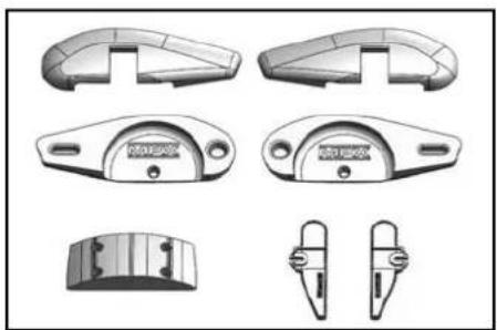
natural_image
Technical drawings of mechanical components with no visible text or symbols# 22 4416 # 22 4410
natural_image
Collection of mechanical parts including bolts, flanges, and bolts (no text or symbols visible)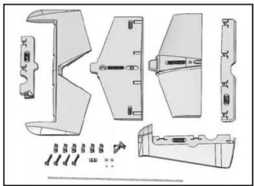
natural_image
Exploded view diagram of a mechanical component with exploded views and assembly details (no text or labels)# 22 4408
natural_image
Technical line drawing of a boat hull with structural details (no text or symbols)# 72 4370 Dekor
# 73 3109 Prop 14x7"
33 3046
text_image
MASCENT HIMAX MUSTRIEUX KOOKSTARK KOOKSTARK KOOKSTARK KOOKSTARK MULTIPLEX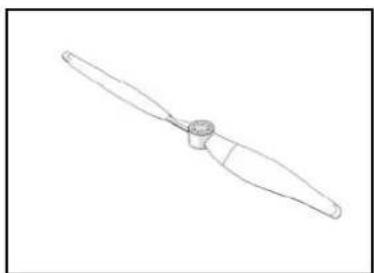
natural_image
Line drawing of a propeller blade with a central hub (no text or symbols)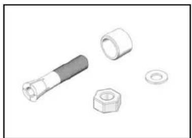
natural_image
Illustration of mechanical components including a bolt, nut, and washer (no text or symbols)# 33 3046
7 2236
# 11 2088
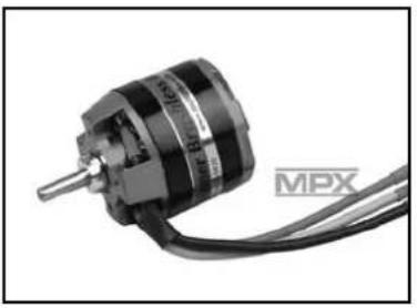
Himax C 4220-0620
MULTIcont BL-60 SD
Servo HS-82MG
natural_image
Close-up of a black MPX electric motor with attached cable (no visible text or symbols)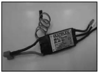
text_image
MULTI-50FT BIL40 3D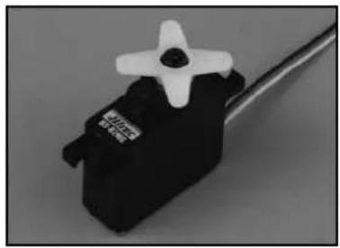
natural_image
Close-up of a black and white servo motor with a white head and screw, mounted on a wire (no visible text or symbols)MULTIPLEX®