Heron - Remote control toy MULTIPLEX - Free user manual and instructions
Find the device manual for free Heron MULTIPLEX in PDF.

| Product type | RC model (glider / motor glider) |
| Brand | Multiplex |
| Model | Heron |
| Wingspan | 2400 mm |
| Overall length | 1100 mm |
| Flight weight (glider) | From 1350 g |
| Flight weight (electric) | From 1550 g |
| Wing area (FAI) | Approx. 41.3 dm² |
| Wing loading | From 32.7 to 37.5 g/dm² |
| RC functions | Elevator, rudder, ailerons, flaps (butterfly), motor or tow hook |
| Center of gravity | 65 mm measured from leading edge (at fuselage) |
| Power system (motor) | Propulsion kit "Solius / Heron" with Brushless motor BL-O 3516-0850, ESC MULTIcont BL 40 S-BEC |
| Recommended flight battery | Li-BATT eco 3/2200 (M6) or equivalent 3S LiPo |
| Recommended receiver | Multiplex RX-7-DR light M-LINK (no. 5 5810 or 5 5818) |
| Recommended servos | 2x Nano-S (elevator+rudder), 4x Tiny-S (2 ailerons+2 flaps) |
| Structure material | ELAPOR® foam (modified polystyrene) |
| Recommended adhesives | Zacki ELAPOR® (cyanoacrylate) or hot glue |
| Minimum age | 14 years (adult supervision for minors) |
| Usage | Outdoor flight in good weather, avoid strong wind, open areas |
| Maintenance | Gentle cleaning, avoid solvents; check glue joints and moving parts before each flight |
| Safety | RC liability insurance mandatory; range test before flight; follow battery charging instructions |
| Spare parts | Complete kit with spare parts available from Multiplex (see list in manual) |
Frequently Asked Questions - Heron MULTIPLEX
User questions about Heron MULTIPLEX
0 question about this device. Answer the ones you know or ask your own.
Ask a new question about this device
Download the instructions for your Remote control toy in PDF format for free! Find your manual Heron - MULTIPLEX and take your electronic device back in hand. On this page are published all the documents necessary for the use of your device. Heron by MULTIPLEX.
USER MANUAL Heron MULTIPLEX
Designed for the MULTIPLEX
brushless power set #332660/333660
D Bauanleitung 2 ... 13
GB Building instructions 14 ... 25
F Notice de construction 26 ... 43
1 Instruzioni di montaggio 44 ... 54
ES Instrucciones de montaje 55 ... 65

Abbildungen
Illustrations
Illustrations
Illnstrazioni
Iustraciones
32-37
Ersatzteile
Replacement parts
Pieces de rechanges
Parti di ricambio
Repuestos
66 - 67
Erhaltliche Varianten / Available versions / Version D disponible / Varianti disponibili / Variantes disponibles

214276
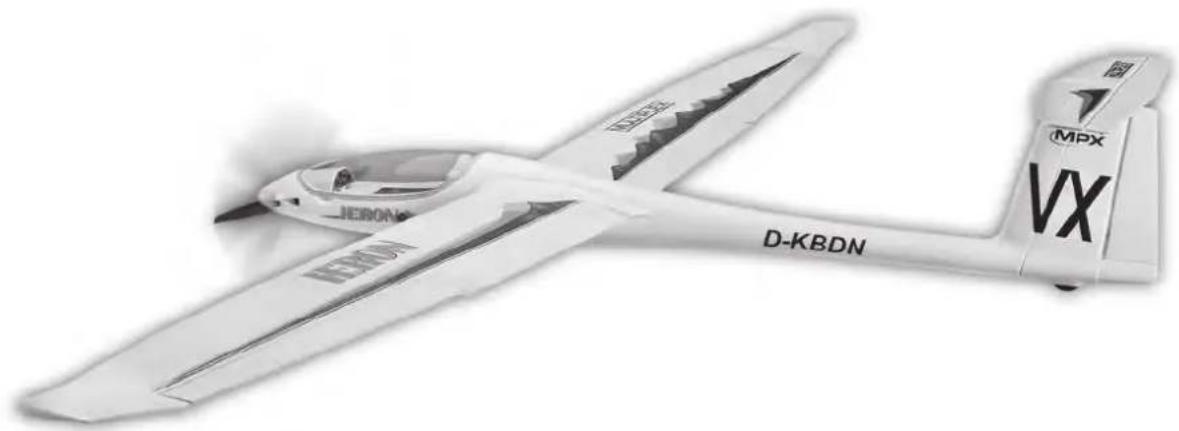
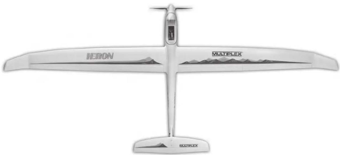
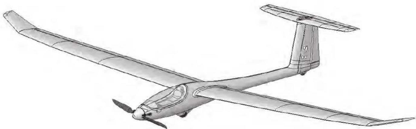
Heron

264276
Heron

Querruder, Flaps (Butterfly),
This model is NOT A TOY in the usual sense of the term.
By operating the model the owner affirms that he is aware of the content of the operating instructions, especially those sections which concern safety, maintenance, operating restrictions and faults, and is capable of fulfilling these requirements.
This model must not be operated by any child under fourteen years of age. If a person below this age operates the model under the supervision of a competent adult who is acting as the child's guardian within the legal sense of the term, this individual is responsible for the implementation of the information in the OPERATING INSTRUCTIONS.
THE MODEL AND ASSOCIATED ACCESSORIES MUST BE KEPT OUT OF THE REACH OF CHILDREN UNDER THREE YEARS OF AGE! MODELS CONTAIN SMALL DETACHABLE PARTS WHICH MAY BE SWALLOWED BY CHILDREN UNDER THREE YEARS. CHOKING HAZARD!
All the warnings in the OPERATING INSTRUCTIONS must be observed whenever the model is operated. Multiplex Modellsport GmbH & Co. KG accepts no liability for loss or damage or any kind which occurs as a result of incorrect operation or misuse of this product, including the accessories required for its operation. This includes direct, indirect, deliberate and accidental loss and damage, and all forms of consequent damage.
Every safety note in these instructions must always be observed, as all the information contributes to the safe operation of your model. Use your model thoughtfully and cautiously, and it will give you and your spectators many hours of pleasure without constituting a hazard. Failure to operate your model in a responsible manner may result in significant property damage and severe personal injury. You alone bear the responsibility for the implementation of the operating instructions and the safety notes.
Approved usage
The model is approved exclusively for use within the modelling hobby. It is prohibited to use the model for any other purpose than that stated. The operator of the model, and not the manufacturer, is responsible for damage or injury of any kind resulting from non-approved use.
The model may only be operated in conjunction with those accessories which we expressly recommend. The recommended components have undergone thorough testing, are an accurate match to the model, and ensure that it functions safely. If you use other components, or modify the model, you operate it at your own risk, and any claim under guarantee is invalidated.
To minimise the risk when operating the model, please observe the following points:
- The model is guided using a radio control system. No radio control system is immune to radio interference, and such interference may result in loss of control of the model for a period of time. To avoid collisions, you must therefore ensure at all times that there is a wide margin of safety in all directions when operating your model. At the slightest sign of radio interference you must cease operating your model!
- Never operate your model until you have successfully completed a thorough check of the working systems, and carried out a range-check as stipulated in the instructions supplied with your transmitter.
- The model may only be flown in conditions of good visibility. You can avoid being temporarily blinded by not flying towards the sun, or in other difficult light conditions.
- A model must never be operated by a person who is under the influence of alcohol, drugs or medication which have an adverse effect on visual acuity and reaction time.
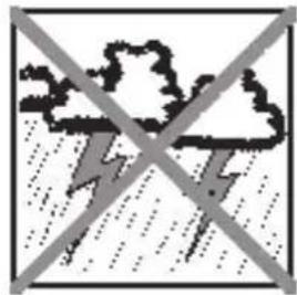
- Only fly your model in conditions of wind and weather in which you are able to maintain full control of the model. Even when the wind is light, bear in mind that turbulence can form at and around objects which may have an effect on the model.
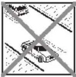
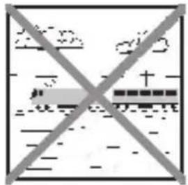
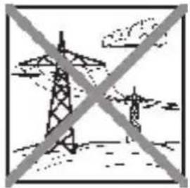
- Never fly in any location where you may endanger yourself of others, e.g. close to residential areas, overhead cables, open roads and railway lines.
- Never fly towards people or animals. You may think that flying low over other people's heads is proof of your piloting skill, but all it does is place others at unnecessary risk. It is in all our interests that you let other pilots know that this is what you think. Always fly in such a way that you do not endanger yourself or others. Bear in mind that even the best RC system in the world is subject to outside interference. No matter how many years of accident-free flying you have under your belt, you have no idea what will happen in the next minute.
Residual risks
Even if the model is operated in the correct manner, and you observe all safety aspects, there is always a certain residual risk.
For this reason it is mandatory to take out third-party liability insurance. If you join a club or flying association, insurance is usually available or included in the annual fee. Make sure that your insurance cover is adequate (i.e. that it covers powered model aircraft). Always keep your models and your radio control equipment in perfect order.
The following hazards may occur owing to the model's construction and type:
- Injury caused by the propeller: you must keep well clear of the area around the propeller from the moment that the battery is connected. Please bear in mind that objects in front of the propeller may be sucked into it, and objects behind the propeller may be blown away by it. The model may start moving when the propeller starts to turn. You must therefore position the model in such a way that it cannot move towards other persons if the motor should unexpectedly start running. When you are carrying out adjustment work involving the running motor, you must ensure that the model is always held securely by an assistant.
- Crash caused by pilot error: this can happen even to the best of pilots, so it is essential to fly exclusively in a safe environment: an approved model flying site and suitable insurance are basic essentials.
- Crash caused by technical failure or unnoticed damage in transit or in the workshop. A thorough check of the model before every flight is essential. However, you should also take into account at all times that material failures can and do occur. Never fly in a location where your model may damage or injure others.
- Keep within the stated operating limits. Excessively violent flying will weaken the airframe, and may result in sudden material failure, or may cause the model to crash during a subsequent flight due to "creeping" consequent damage.
- Fire hazard caused by electronic failure or malfunction. Store batteries safely, and always observe safety notes which apply to the airborne electronic components, the battery and the battery charger. Protect all electronic equipment from damp. Ensure that the speed controller and battery are adequately cooled.
The instructions which accompany our products must not be reproduced and / or published, in full or in part, in print or any electronic medium, without the express written approval of Multiplex Modellsport GmbH & Co. KG.
Examine your kit carefully!
MULTIPLEX model kits are subject to constant quality checks throughout the production process, and we sincerely hope that you are completely satisfied with the contents of your kit. However, we would ask you to check all the parts (referring to the Parts List) before you start construction, as we cannot exchange components which you have already modified. If you find a part is not acceptable for any reason, we will gladly correct the defect or replace the item in question once we have inspected it. Please send the component to our Service Department, with adequate postage pre-paid, being sure to include the completed complaints form. We are constantly working on improvements to our models, and for this reason we must reserve the right to change the kit contents in terms of shape or dimensions of parts, technology, materials and fittings, without prior notification. Please understand that we cannot entertain claims against us if the kit contents do not agree in every respect with the instructions and the illustrations.
Caution!
Radio-controlled models, and especially model aircraft, are by no means playthings in the usual sense of the term. Building and operating them safely requires a certain level of technical competence and manual skill, together with discipline and a responsible attitude at the flying field.
Errors and carelessness in building and flying the model can result in serious personal injury and damage to property. Since we, as manufacturers, have no control over the construction, maintenance and operation of our products, we are obliged to take this opportunity to point out these hazards and to emphasise your personal responsibility.
Warning:
Like every aeroplane, this model has static limits. Steep dives and senseless manoeuvres inappropriate to the type may result in the loss of the aircraft. Please note: we will not replace the model in such cases. It is your responsibility to approach the airframe's limits gradually. It is designed for the power system recommended in these instructions, but is only capable of withstanding the flight loads if built exactly as described and if it is in an undamaged state.
Airborne radio control system components / other accessories
Recommended equipment:
MULTIPLEX receiver, min. RX-7-DR light M-LINK Order No. 5 5810
or RX-7-DR light M-LINK Order No. 5 5818
You may also wish to exploit one of our telemetry-capable M-LINK receivers, and equip your model with sensors such as the Vario / altimeter and current sensors.
- 2 x Nano-S servos (elevator + rudder) Order No. 6 5120
- 4 x Tiny-S servos (2 x aileron + 2x flap) Order No. 6 5121
- 4 x Servo extension leads, 30 cm Order No. 8 5031 (for fuselage)
- 2 x Servo extension leads, 40 cm
- 2 x Servo extension leads, 60 cm
or * => # 65170 ServoSet Heron with extension leads
Order No. 8 5029 (for ailerons in wings)
Order No. 8 5032 (for elevator and rudder)
Power set with matching flight battery:
"Solius / Heron" power set, Li-BATT powered Order No. 33 3660 with BL-O 3516-0850 brushless motor, MULTlcont BL 40 S-BEC speed controller also Li-BATT eco 3/2200 flight battery (M6). 12× 6" folding propeller, propeller hub, spinner and accessories supplied in the kit as standard!
Power set:
"Solius / Heron" power set Order No. 33 2660 with BL-O 3516-0850 brushless motor, MULTicont BL 40 S-BEC speed controller 12× 6 folding propeller, propeller hub, spinner and accessories supplied in the kit as standard!
Recommended flight battery:
Li-BATT FX 3/1-2200 (M6) Order No. 157351
Adhesives:
Zacki ELAPOR 20g Order No.59 2727
Zacki ELAPOR 器 Super liquid, 10g Order No.59 2728
Hot-melt adhesive, contact cement for canopy
Battery charger:
HiTEC Multicharger X1 AC Plus, with power supply AC/DC 100-240V/10-18V 6,0A
Order No. 114 118
Tools: Balsa knife, side-cutters, screwdriver (for M3 and M5), 13 mm A/F spanner, hot-melt glue gun.
Important note
This model is not made of Styrofoam™, and it is not possible to glue the material using white glue, polyurethane or epoxy; these adhesives only produce superficial joints, and simply break away under stress. Please be sure to use medium-viscosity cyano-acrylate glue exclusively, preferably Zacki ELAPOR® # 59 2727, which is optimised specifically for ELAPOR® particle foam. If you see Zacki ELAPOR® there is usually no need for cyano 'kicker' or activator. However, if you wish to use a different adhesive which requires the use of activator, please note that these materials are injurious to health, and should always be applied in the open air. Take care when handling all cyano-acrylate adhesives, as they harden in seconds, so don't get them on your fingers or other parts of the body. We strongly recommend the use of goggles to protect your eyes. Keep the adhesive out of the reach of children! For certain joints it is also possible to use hot-melt adhesive; the instructions indicate where this is the case.
Working with Zacki ELAPOR®
Zacki ELAPOR® has been developed specifically for glued joints in our models which consist of moulded ELAPOR® foam parts.
Please observe the following points in order to obtain perfect joints:
- Avoid the use of activator. 'Kicker' significantly weakens the joint. We advise leaving joined parts for 24 hours to obtain maximum strength, particularly when the glued area is large.
- Activator should only be used for temporary, small-area joints ('tacking'). Spray a little activator on one surface, and allow it to air-dry for about thirty seconds.
To obtain maximum joint strength you should lightly sand the surface with 320-grit abrasive paper before applying glue.
Bent parts - actually don't exist. If you find that a component has taken up a curve, perhaps after being transported, it is easy to straighten again. In this respect ELAPOR® behaves in a similar way to metal: bend the component back slightly beyond the correct position, and the material will then spring back to its proper shape when released, and maintain it. There are limits, however - don't overdo it!
Bent parts - really do exist. If you wish to paint your model, apply MPX Primer # 60 2700 to the surfaces, wiping it on very lightly as if you were cleaning the model. Paint must always be applied thinly and evenly, otherwise the component will warp. Then you really will have bent parts, and they will also be heavy and perhaps even unusable. We have found that matt-finish paints produce the best visual effect.
Specification:
Wingspan 2400 mm
Overall length 1100 mm
All-up weight, glider min. 1350 g
All-up weight, electric min. 1550 g
Wing area approx. 41,3 dm² (FAI)
(FAI = > wing ^+ tailplane, excl. fuselage)
Wing loading min. 32,7 / 37,5 g/dm²
RC functions:
Elevator, rudder, ailerons, flaps (Butterfly),
motor speed,
optional tow release
The Centre of Gravity is located at a point 65mm aft of the wing root leading edge (measured at the fuselage).
Note:
Please separate the pictorial pages from the centre of the building instructions before you start construction.
1. Before starting construction
Please check the contents of your kit.
You will find Figs. 1, 2 and the Parts List helpful here.
2. Cutting the GRP longerons to length
Use a pair of side-cutters to cut the 2mm × 800mm GRP rods 69 to the stated lengths to form the fuselage longerons: 1× 243mm / 1× 282mm / 1× 218mm / 2× 326mm
Cut the 1.3mm × 650mm GRP rods 68 to the following lengths to form the stiffeners for the tailplane and fin: 2× 215mm and 2× 400mm
Fig. 3
3. Gluing the fuselage longerons in place
When you have cut the fuselage longerons 69 to length, they can be glued in the fuselage shells 3 and 4: the 326 mm longerons are fitted to the sides at the front, while the 218~mm longeron is installed at front bottom in the right-hand fuselage shell 4.
The 243~mm longeron should be glued in the turtle deck of the right-hand fuselage shell. The underside aft of the undercarriage is reinforced with the 282~mm longeron.
This is the procedure: first allow a little Zacki ELAPOR® to run into the channel, then press the longeron into place. Finally run Zacki ELAPOR® super liquid along the length of the channel.
Fig. 4
4. Gluing the latch catches and the motor bulkhead in the fuselage
Glue the latch catches 22 in both fuselage shells (right and left).
Glue the motor bulkhead 50 in the recess in the right-hand fuselage nose 4 using Zacki ELAPOR®.
Fig. 5
5. Preparing the cable holders
Use cyano to glue the socket of the 300mm extension leads #8 5031 to the cable holders 34, keeping the ends flush. Route the leads through the strain relief lugs as shown.
Fig. 6
6. Installing the cable holders
Glue the cable holders 34 in the appropriate recesses in both fuselage shells. Use Zacki ELAPOR® (without activator), and push them in swiftly as far as they will go.
Fig. 7
7. Installing the wheel frame
Glue the wheel frame 52 in one of the two fuselage shells using Zacki ELAPOR®. Ensure that no adhesive gets inside the through-hole for the screw.
Fig. 8
8. Installing the fuselage stiffening tube and cables
Wipe activator over the hexagonal fuselage stiffening tube 66, then apply thick cyano to the surfaces of the appropriate channel in the fuselage shell. Swiftly push the tube into the channel, taking care to keep the fuselage perfectly straight. Allow the adhesive to set hard, then slip the 600~mm extension leads # 8 5032 through the tube. Temporarily tape the leads to both ends to prevent them slipping out again.
Fig. 9
9. Installing the rudder and elevator servos
First set the servos to neutral (centre) from the transmitter. Check that the clevis 33 and the pre-formed rudder pushrod 31 are a snug fit in the holes in the servo output arms; you may need to open up the holes slightly.
Connect the clevis to the innermost hole in the elevator servo output arm. The pre-formed rudder pushrod is later connected to the centre hole of the rudder servo output arm.
Centre the servo from the transmitter (or use a servo tester), and push the output arms onto the servo shafts, keeping them at right-angles to the case sides.
Connect the servo leads to the extension leads projecting from the fuselage stiffening tube 66, and tape the plugs and sockets together for security before drawing them forward through the tube. On the inside of the right-hand fin moulding you will find a circular void in which about 3cm of the servo leads can be stowed.
If you ever need to replace the servos or repair them (new gears), the extra cable allows easier access to the ser- vos, and there will be a little spare cable available for any soldered joints required. Push the remainder of the two servo leads into the appropriate channels in the right-hand fuselage shell before they "disappear" into the fuselage stiffening tube.
The servos themselves should be installed as shown in the illustration. It is sufficient to secure each servo by applying a little hot-melt adhesive to the outside of the mounting lugs. This method makes it easy to remove the servos for
subsequent repair without damaging the fin.
Fig. 10
10. Joining the fuselage shells
Please take particular care over this stage, as it is important to the overall success of the model.
Carefully sand the joint surfaces using 320-grit abrasive paper, then place the fuselage shells together "dry" - without glue. Check that the halves fit together snugly, without requiring force. Make any minor adjustments required to obtain a good fit.
Apply thick Zacki Elapor to the joint surface of one fuselage shell, then swiftly fit the two shells together, taking care to align everything accurately.
Hold the fuselage together for a few minutes, pressing the shells inwards lightly, and checking constantly that the component is completely straight. Don't try bending it or placing it under strain, as the cyano-acrylate needs a little while to achieve full strength.
Fig. 11
11. Installing the tailplane screw support
Press the two M5 nuts 36 into the cylindrical screw guides in the tailplane screw support 59, then glue the support 59 in the recess in the right-hand fuselage shell 4 using Zackie Elapor.
Fig. 12
12. Completing the elevator linkage
Screw the clevis 33 onto the end of the elevator pushrod 32 and adjust it so that the distance between the two linkage points is about 136~mm . Slip the pre-formed end of the rod through the hole in the tailplane screw support 59, and engage the clevis in the innermost hole in the elevator servo output arm.
Fig. 13
13. Completing the fin
Glue the left fin moulding 9 to the right fin shell, which is an integral part of the fuselage. Take great care to avoid adhesive getting into the elevator pushrod guide.
Fig. 14
14. Installing the fin stiffeners
The channels in both sides of the fin are intended to accept the 1.3mm stiffener rods 68, which are 215~mm long. This is accomplished by running a little Zacki Elapor into the recesses, then pressing the stiffeners into place. Complete the job by running thin cyano along the length of both stiffeners; apply a little activator to speed up the curing process.
Fig. 15
15. Installing the tailwheel
- Glue the dummy tailwheel 57 to the raised area at the tail end of the fuselage.
Fig. 16
16. Cutting the rudder free
Use a sharp modelling knife to complete the cut at the bottom of the rudder. Align the blade with the existing surface to obtain a neat cut line.
Move the rudder to and fro repeatedly until the hinge is free-moving.
Fig. 17
17. Completing the rudder horn and linkage
Fit the socket-head grubscrew 28 in the swivel connector barrel 27, and snap it into the "Twin" horn 26.
Apply Zacki ELAPOR®/Hotglue to the recess for the horn, and push the horn into place as shown in the illustration. Engage the pre-formed end of the rudder pushrod 31 in the centre hole in the servo output arm, and slip the straight end of the rod through the hole in the swivel barrel 27. Check the neutral position before tightening the socket-head grubscrew 28 using the allen key 29.
Fig. 18
18. Installing the motor (powered glider version)
Screw the motor to the motor bulkhead 50 as described in the instructions supplied in the power set.
Fig. 19
Connect the speed controller and check the direction of rotation of the motor shaft (without fitting the propeller) from the transmitter: when you look at the motor from the front, the output shaft must rotate anti-clockwise. If this is not the case, swap over any two of the three power wires to the motor.
Caution: never connect the flight battery to the speed controller unless your transmitter is already switched on, and you are certain that the throttle control is at the "OFF" position.
Secure the speed controller in the fuselage with Velcro (hook-and-loop) tape at the left side, and fix the power wires to the fuselage side with hot-melt adhesive.
The "Solius / Heron" brushless power set # 33 3660 including battery constitutes an excellent power system for the model.
The components in our power set have been thoroughly tested, and are carefully matched to each other. Of course, you may wish to use different batteries, controllers, motors or radio control system components at your own discretion, but we will not be able to offer support if you do so.
Alternatively the model can be completed as a pure glider. For this version you simply have to glue the glider nose cone 10 to the tip of the fuselage. As an option for the glider version you may wish to install an aero-tow mechanism #723470. This is actuated using a scrap piece of snake outer sleeve (3 / 2mm) and a length of 1mm steel rod.
19. Installing the spinner and propeller
First attach the folding propeller blades 82 to the propeller hub 80 using the cheesehead screws 75 (M3 x 20 mm) and the self-locking nuts 76. Tighten the screws just to the point where the propeller blades swivel smoothly when folded back, but exhibit no lost motion.
Now slip the prepared propeller hub onto the taper collet 79 as shown in the illustration, before fitting the whole assembly onto the motor shaft. Note that there should be about 1mm clearance between the propeller hub and the front face of the fuselage.
Slip the plain washer 72 on the propeller hub, followed by the shakeproof washer 73, and then fit and tighten the M8 nut 74. Ensure that the clearance between the propeller hub and the fuselage is still present! The spinner 81 is secured using the M2.5 x 12 screw 77.
Fig. 20
20. Installing the battery retainer system
First attach the retaining strap 25 to the lower recess in the battery support plate 51, then glue the plate 51 in the front of the fuselage using hot-melt adhesive.
Fig. 21
21. Installing the main wheel
Install the wheel 12 in the wheel frame 52 together with the two spacer sleeves 43, and secure it with the M3 x 30 mm screw 38 and the M3 self-locking nut 39. Check that the nut engages in the hexagonal recess.
Fig. 22
22. Preparing the tailplane
Glue the two 400 × 1.3 mm stiffeners in the tailplane 6 to strengthen it.
Fig. 23
23.Preparing the tailplane
Glue the spreader plate 58 to the top of the tailplane.
Fig. 24
24. Attaching the horn to the elevator
The elevator horn 60 should be glued to the underside of the elevator. Take care that no adhesive runs into the pushrod sleeve (cross-hole). Observe the installation position!
Fig. 25
25. Tubular spars
The tubular spar sleeves / and spar tubes 64 + 65 are already installed in the wings, but the ends need to be cleaned up slightly so that they are an easy sliding fit in the opposite rib when the model is assembled.
Fig. 26
26. Reinforcing the ailerons and flaps, freeing up the hinges
Glue the stiffening tubes 67 in the appropriate channels in the ailerons and flaps (4x).
When you have done this, cut the ailerons / flaps free at both ends and flex them up and down repeatedly until the hinge lines move freely. On no account cut off the ailerons / flaps along the hinge line!
Fig. 27
Tip: if the hinge line should tear at any time, a drop or two of cyano will repair the damage.
27. Installing the aileron / flap servos
The first step is to set the servos to neutral from the transmitter. Fit the output arms on the servo shafts, angled forward by two splines relative to the case sides (prepare the servos as a mirror-image pair). This arrangement provides mechanical aileron differential, if your transmitter does not feature suitable electronic facilities (differential mixer). Angling the output arms in this way ensures by mechanical means that the up-travel of the ailerons is greater than their down-travel.
Use this setting to achieve even greater deflections for the butterfly landing position.
The flap servos in neutral position the servo arm to be rotated 2 teeth to the rear - for housing (mirror image).
The possible rash becomes enlarged down!
Connect the aileron servo lead with the 400mm extension cords # 8 5029th Set the servos and the cable into the recesses of one. The connections of the power cable must be 46mm above the root rib out. Secure the servos with hot glue to the tabs and insert the cable with transparent tape on the cable channel.
Fig. 28 + 31 + 31b
28. Installing the root ribs
Attach the retaining clips 55 to the left root rib 53 and right root rib 54 using the screws 37. Push the 8 × 2 ~mm O-rings 41 over the retaining clips to keep them under light tension. Fig. 29
Route the servo leads through the opening in the root rib, and then glue the root rib to the wing using Zacki ELAPOR®. Repeat the procedure with the second wing panel.
Fig. 30
29. Installing the aileron / flap horns
Fit the socket-head grubscrews 28 in the swivel connector barrels 27 and snap them into the "Twin 10 × 20 " horns 26.1 in the outer hole. Glue the prepared horns in the recesses in the ailerons / flaps using Zacki ELAPOR® / hotglue.
Fig. 31 => ailerons
Fig. 31b flaps Observe the installation position!
30. Installing the aileron pushrods
Connect the pre-formed end of the aileron pushrod 30 (60mm) to the middle hole in the servo output arm.
Connect the pre-formed end of the flap pushrod 30.1 (70mm) to the outer hole in the servo output arm.
Slip the straight end of the pushrod through the swivel barrel mounted on the aileron horn, and tighten the grubscrew in the barrel after checking that the servo and aileron are at neutral. Repeat the procedure with the other wing.
Fig. 31 + Fig. 31b
31. Attaching the servo fairings
Place the left servo fairing 61 and the right fairing 62 over the servos and pushrods as shown in the illustration.
Fig. 32
32. Assembling the canopy
The cockpit area looks particularly realistic if you paint the inside of the canopy frame 5. The best results are obtained using ELAPOR® COLOR paints. For example, the frame could be painted grey # 60 2711 and the instrument panel cover black # 60 2712. The moulded-in seat area and headrest look convincing if painted blue # 60 2703. Allow the paint to dry before attaching the instrument panel sticker. If you are not confident with painting, we recommend that you apply the printed seat sticker from the decal sheet as well as the instrument panel sticker.
Glue the clear canopy 11 to the canopy frame 5, using an adhesive such as clear contact cement.
The conventional method of using this type of adhesive is to allow it to air-dry before joining the parts, but in this case it is better to apply the glue, fit the canopy immediately, and tape it temporarily to the fuselage. Allow the glue plenty of time to dry out. Be sparing with the adhesive, otherwise you could stick the canopy frame to the fuselage. A piece
of thin plastic film between the two parts will prevent this.
The latch tongues 23 should now be glued in the slots in the canopy frame 5, pushing them in until the "teeth" disappear. This is the procedure: first glue them in place with Zacki ELAPOR®, then immediately fit the canopy on the model so that the latches are able to align themselves accurately. Wait at least two minutes before removing the canopy again. Now ply rops of Zacki ELAPOR® super liquid in the gaps at the latch tongues to reinforce the glued joints.
Figs. 33 + 34
33. Attaching the wings to the fuselage
Connect the aileron / flap servo plugs to the sockets mounted in the fuselage before sliding the wings into place. The wings are held against the fuselage by fitting the locking pin 56 between the wings panels. It is a good idea to attach the locking pin to the inside the fuselage with a length of string to prevent it becoming lost.
Fig. 35
34. Installing the tailplane
Slip the pre-formed end of the elevator pushrod (L-bend) 32 into the elevator horn 60 from the side, then place the tailplane on the fin.
Fig. 36
35. Securing the tailplane
Fix the tailplane to the fin using the two plastic M5 x 35 screws 35.
Fig. 37
36. Final assembly
Connect the receiver and speed controller, and fix them in the fuselage using the Velcro straps 20 and 21. Temporarily install the flight battery to allow you to check the Centre of Gravity (see Point 38 / Fig. 41).
Fig. 39
The leads which emerge from the rear end of the fuselage can be bundled together neatly using the cable ties 42 included in the kit.
The canopy is fitted by first engaging it at the rear, then pressing it down at the front so that the latch tongues engage in the catches.
Fig. 38
37. Applying the decals
The kit is supplied with a decal sheet 2; the individual name placards and emblems are pre-cut. Apply them to the model in the positions shown in the kit box illustration, or in another arrangement which you find pleasing.
38. Balancing the model
Like every other aircraft, your Solius must be balanced at a particular point if it is to fly efficiently and stably. Assemble the model completely, ready to fly.
The Centre of Gravity should be at a point 65mm back from the leading edge of the wing, measured where the wings meet the fuselage. Support the model at the marked points on two fingertips, and the aeroplane should balance level. Adjust the flight battery to balance the model correctly,
and / or glue the appropriate number of ballast balls 40 in the fin. We cannot state exactly how much ballast is required due to manufacturing tolerances in the foam density, and the different airborne equipment for the glider and electric glider versions. Mark the location of the airborne components in the fuselage once you have found the correct location, so that you can be sure always to replace the battery in the same position. Apply the fin sticker over the trim weight openings.
Fig. 41
- Setting the control surface travels (guideline only!) The control surface travels must be correct, otherwise the model will not respond harmoniously to control commands. All travels are measured at the widest point of the control surface concerned.
Elevator
up (stick back) approx. + 10 mm
down (stick forward) approx. - 10 mm
Powermix approx. - 0,5 mm
Down-elevator mix with Flap
speed /thermic approx. -1,5/-1,5 mm
Rudder
left and right approx. 20mm
each side of centre
Ailerons
up approx. +16mm
down approx. - 8 mm
Flap approx. +2 / - 2mm
Flaps (camber-changing flaps)
aileron approx. +10mm
up (Speed) approx. + 3 mm
down (Thermic) approx. -3,5 mm
Spoilers (butterfly)
both ailerons up approx. +22mm
both flaps down approx. - 26 mm
Down-elevator mix with spoiler approx. - 5 mm
Both ailerons can be set to move up and both flaps move down simultaneously in order to provide a "spoiler" function, i.e. to shorten the landing approach; this is known as the "butterfly" or "crow" braking system. At the same time a suite-ble amount of down-elevator trim must be mixed in to keep the model in a stable attitude. This can only be done if your radio control system features suitable mixers.
If you are not sure of this, please refer to the instructions supplied with your radio control system.
The Butterfly adjustment allows if needed steep and targeted landing approaches in difficult terrain.
Note: when you apply a right-alleron command, the righthand aileron - as seen from the tail, looking forward - must deflect up.
Simultaneously, the right flap halfway with running upwards. When an aileron down the flap does not work with down!
If you cannot set the stated control surface travels using your radio control system's electronic adjustment facilities, you may need to connect the pushrod to a different linkage hole.
Ensure that all the radio control system components are properly installed and connected. Check the control surface centres and travels, the direction of rotation of the servos, and the freedom of movement of the control system components. Ensure that the power leads cannot come into contact with the rotating motor barrel (secure them with hot-melt adhesive). Check once more that the motor shaft rotates in the correct direction - please take care!
40. Preparations for the first flight
For the first flight wait for a day with as little breeze as possible; the evening hours often offer calmer conditions. It is essential to carry out a range-check before the first flight! Please follow the instructions laid down by your RC system manufacturer.
The transmitter battery and flight pack must be fully charged in accordance with the manufacturer's recommendations. Before switching the system on, ensure that your chosen channel is free; this does not apply if you are using a 2.4 GHz system.
If you are unsure about any point, do not fly the model! If you cannot identify and cure the problem, send the whole RC system (including battery, switch harness and servos) to your system manufacturer for checking.
41. Maiden flight ...
The aircraft is designed to be hand-launched (always into wind).
If you are a beginner to model flying, we strongly recommend that you ask an experienced modeller to help you for the first few flights. Once the model has reached a safe height, adjust the control surfaces using the trims on the transmitter, so that the model flies straight and level "hands-off".
Powered version: with the aircraft flying at an adequate altitude, check how it responds when the motor is switched off, so that you are familiar with its behaviour on the glide. Carry out repeated simulated landing approaches at a safe height, as this will prepare you for the real landing when the battery is discharged.
Avoid flying tight turns at first, especially close to the ground, and in particular during the landing approach. It is always better to land safely some distance away than to risk a crash by forcing the model back to your feet.
42. Thermal flying
Making the best use of flat field thermals is not particularly easy, and calls for considerable skill and experience. Areas of rising air are harder to detect and recognise at a flat field, because they tend to occur at higher altitude than at the hillside, where it is often possible to find lift while the model is cruising along the edge of the slope, and then circle away in it. A thermal at a flat field which occurs directly overhead is very hard to recognise, and to exploit it to the full requires a highly skilled pilot. For this reason it is always best to go thermal seeking off to one side of where you are standing. You will recognise thermal contact by the glider's behaviour. Good thermals are obvious because the model will climb strongly, but weak thermals take a practised eye to detect,
and you will need a lot of skill to make use of them. With a little practice you will be able to recognise likely trigger points for thermals in the local landscape. The ground warms up in the sun's heat, but heat absorption varies according to the type of terrain and the angle of the sun's rays. The air over the warmer ground becomes warmer in turn, and the mass of warm air flows along close to the ground, driven by the breeze. Strong winds usually prevent thermal buildup. Any obstruction - a shrub or tree, a fence, the edge of a wood, a hill, a passing car, even your own model on the landing approach - may cause this warm air to leave the ground and rise. Imagine a drop of water on the ceiling, wandering around aimlessly, and initially staying stuck to the ceiling. If it strikes an obstruction it will fall on your head. A triggered thermal can be thought of as the opposite of the drop of water.
The most obvious thermal triggers include sharply defined snow fields on mountain slopes. The air above the snow field is cooled, and flows downhill; at the edge of the snow field, part-way down the valley, the cool air meets warm air flowing gently uphill, and pushes it up and away as if cut off by a knife. The result is an extremely powerful but bumpy thermal bubble. Your task is to locate the rising warm air and centre your model in it. You will need to control the glider constantly to keep it centred, as you can expect the most rapid climb rate in the core of the thermal. Once again, this technique does demand some skill.
To avoid losing sight of the machine be sure to leave the thermal in good time. Remember that a glider is always easier to see under a cloud than against a clear blue sky. If you have to lose height in a hurry, do bear the following in mind:
The structural strength of the Heron is very great for this class of model, but it is not infinite. If you attempt to destroy the model forcibly, please don't expect any sympathy or compensation from us (alas, we speak from experience).
43. Flying at the slope
Ridge soaring is an extremely attractive form of model flying. Soaring for hours on end in slope lift, without needing any outside aid for launching, must be one of the finest of modelling experiences. But to "milk" a thermal to the limits of vision, bring it down again in a continuous series of aerobatic manoeuvres, and then repeat the whole show - that must surely be the last word in model flying.
But take care - there are dangers for your model lurking at the slope. Firstly, in most cases landing is much more difficult than at a flat field site. It is usually necessary to land in the lee of the hill where the air is turbulent; this calls for concentration and a high-speed approach with last-minute airbrake extension. A landing on the slope face, i.e. right in the slope lift, is even more difficult. Here the trick is to approach slightly downwind, up the slope, and flare at exactly the right moment, just before touch-down.
44. Aero-towing
An ideal combination for learning to aero-tow, and for actual aero-towing, is a FunCub and a Heron.
For the tow you require a 20m length of braided cable of 1 to 1.5mm . Tie a loop of nylon line (0.5mm) to the
glider end of the cable; this acts as a "weak link", in case the tow should go badly wrong.
A loop in the other end of the towline should be connected to the aero-tow coupling of the FunCub. Assemble the models, connect them as described, and set them up directly into wind, the glider behind the tug. Check that the towline is resting on top of the FunCub's tailplane. The tug now rolls forward until the towline is taut, and only then should the tug's pilot apply full-throttle. Both aeroplanes accelerate: the tug stays on the ground initially, while the glider lifts off, but the glider pilot keeps his model flying low above the ground, directly in the wake of the tug; the tug can now lift off safely. The two models should be kept climbing steadily, even through turns. Avoid flying directly over your heads during the first few attempts at aero-towing, as it is difficult to detect the models' attitudes from this angle. To drop the tow, operate the transmitter control which opens the tow release mechanism.
45. Electric flying
With the electric version you have the optimum level of autonomy and independence. You can fly from a flat field and carry out about seven climbs to a sensible gliding height (around 150m ) from a single battery charge. At the slope you can also keep the electric power system as a "lifebelt", i.e. you only use the motor to "keep afloat", and avoid landing out, i.e. landing at the bottom of the slope when the lift fails.
46. Flight performance
What is meant by a glider's performance?
The two most important parameters are sinking speed and glide angle. Sinking speed is a measure of the vertical height lost per second relative to the surrounding air. The sinking speed is primarily determined by the wing loading (weight relative to wing area). Here the Heron offers a really excellent performance - much better than conventional models - as its wing loading is so low. This means that only slight thermal assistance is necessary (warm air rising) to cause the model to gain height. Wing loading is also the main factor in determining the model's airspeed - the lower the loading, the slower the model. Low airspeed means that the model can be turned extremely tightly, and this is also advantageous when thermal flying, as areas of lift are usually very small when close to the ground.
The other important parameter in glider performance is the glide angle. This is stated as a ratio, i.e. from a particular altitude the model flies such and such a distance. The glide angle increases as wing loading rises, and at the same time - of course - the model's airspeed increases. This becomes necessary if you wish to fly in relatively strong winds, and when you need "energy retention" for flying aerobatics.
For thermal flying you need a good glide angle too, as this is the key to flying across areas of "sink" (the opposite of a thermal) quickly, so that you can seek out another thermal.
47. Safety
Safety is the First Commandment when flying any model aircraft. Third party insurance is mandatory. If you join a model club, suitable cover will usually be available through the organisation. It is your personal responsibility to ensure that your insurance is adequate (i.e. that its cover includes powered model aircraft). Make it your job to keep your
models and your radio control system in perfect order at all times. Check and observe the correct charging procedure for the batteries you are using. Make use of all sensible safety systems and precautions which are advised for your system. An excellent source of practical accessories is the MULTIPLEX main catalogue or our website www.multiplex.de
MULTIPLEX products are designed and manufactured exclusively by active modellers for practising modellers. Always fly with a responsible attitude. You may think that flying low over other people's heads is proof of your piloting skill; others know better. The real expert does not need to prove himself in such childish ways. Let other pilots know
that this is what you think too, as it is in all our interests. Always fly in such a way that you do not endanger yourself or others. Bear in mind that even the best RC system in the world is subject to outside interference. No matter how many years of accident-free flying you have under your belt, you have no idea what will happen in the next minute. Before every flight, check that the battery, the wings and the tailplane are attached and firmly seated. Check in turn that each control surface is operating correctly!
We - the MULTIPLEX team - hope you have many hours of pleasure building and flying your new model.
MULTIPLEX Modellsport GmbH &Co.KG
1 1 Building instructions Paper
1.1 1 Complaint form, models Paper
2 1 Decal sheet Printed adhesive film 300 × 1000 ~mm
3 1 L.H. fuselage shell Moulded Elapor foam Ready made
4 1 R.H. fuselage shell, with fin Moulded Elapor foam Ready made
5 1 Canopy frame Moulded Elapor foam Ready made
6 1 Tailplane
7 1 L.H. wing with spar
8 1 R.H. wing with spar
9 1 Left fin moulding
10 1 Glider nose cone (kit version only)
11 1 Clear canopy
12 1 Wheel
Bullded Elapor foam Ready made
ulded Elapor foam Ready made
Iulded Elapor foam Ready made
ulded Elapor foam Ready made
Moulded Elapor foam Ready made
Inj.-moulded plastic Ready made
Plastic 45 mm Ø
Small parts set
203 Velcro tape, hook
213 Velcro tape, loop
22 2 Canopy latch catch
23 2 Canopy latch tongue
25 1 Battery retaining strap
26 1 "Twin" control surface horn
26.1 4 "Twin 10× 20 control surface horn
27 5 Swivel connector barrel
285 Socket-head grubscrew
291 Allen key
302 Aileron pushrod (one Z-bend)
30.12 Flap pushrod (one Z-bend)
31 1 Rudder pushrod (one Z-bend)
32 1 Elevator pushrod (one L-bend)
331 Clevis
34 4 Cable holder
352 Plastic tailplane screw
362 Nut
37 4 Screw (wing retaining clip)
38 1 Machine screw (wheel axle)
39 1 Self-locking nut (wheel axle)
402 Trim ballast
412 O-ring
423 Cable tie
432 Spacer sleeve
Plastic 25 × 60 ~mm
Plastic 25× 60mm
Inj.-moulded plastic Ready made
Inj.-moulded plastic Ready made
Plastic 16 x 200 mm
Inj.-moulded plastic Ready made
Inj.-moulded plastic Ready made
Metal Ready made, 6 mm
Metal M3 x 3 mm
Metal 1.5 A/F
Metal 10x60mm
Metal 10x70mm
Metal 10x50mm
Metal M2, 1.7 Ø x 121/10 mm
Metal M2
Inj.-moulded plastic Ready made
Inj.-moulded plastic M5 x 35 mm
Metal M5
Metal 2.2× 6.5mm
Metal M3 x 30 mm
Metal M3
Metal ball 13 mm Ø / 9 g
Plastic 8× 2mm
Plastic 98 x 2.5 mm
Plastic 3.1 x60x4mm
Plastic parts set
501 Motor bulkhead
51 1 Battery support plate
521 Wheel frame
531 L.H.rootrib
541 R.H.rootrib
55 4 Retaining clip
561 Wing locking pin
571 Dummy tailwheel
581 Tailplane spreader plate
59 1 Tailplane screw support (for nuts)
601 Elevator horn
612 L.H. servo fairing
62 2 R.H. servo fairing
Inj.-moulded plastic Ready made
Inj.-moulded plastic 20 × 60 ~mm
Inj.-moulded plastic Ready made
Inj.-moulded plastic Ready made
Inj.-moulded plastic Ready made
Inj.-moulded plastic Ready made
Inj.-moulded plastic Ready made
Inj.-moulded plastic Ready made
Inj.-moulded plastic Ready made
Inj.-moulded plastic Ready made
Inj.-moulded plastic Ready made
Inj.-moulded plastic Ready made
Inj.-moulded plastic Ready made
Spars, longerons and stiffeners
63 2 Outer spar sleeve in wing Square CFRP 5,5× 3,5× 200mm
64 2 Outer spar sleeve in wing Square aluminium 10× 8× 900mm
65 2 Inner spar tube in wing Square CFRP 8.8× 6.9× 1.5× 900
66 1 Fuselage stiffening tube Hex. GRP 12 A/F x 0.4 x 560 mm
67 4 Aileron / Flaps stiffening tube Stainless steel tube 3 × 2.6 × 330mm
* supplied length 650 mm => cut to length as listed below:
| 68 2 | GRP rod | GRP 1.3 Ø x 650 mm* | |
| 68 1 | R.H. fin stiffener | GRP 1.3 Ø x 215 mm (650 mm*) | |
| 68 1 | L.H. fin stiffener | GRP 1.3 Ø x 215 mm (650 mm*) | |
| 68 1 | Top tailplane stiffener | GRP 1.3 Ø x 400 mm (650 mm*) | |
| 68 1 | Bottom tailplane stiffener | GRP 1.3 Ø x 400 mm (650 mm*) | |
* supplied length 800 mm => cut to length as listed below:
| 69 2 | GRP rod | GRP | 2Øx800mm* | |
| 69 1 | Bottom fuselage longeron | GRP 2 Ø x 218 mm (800 mm*) | ||
| 69 2 | Side fuselage longeron | GRP 2 Ø x 326 mm (800 mm*) | ||
| 69 1 | Rear fuselage longeron GRP | 2 Ø x 282 mm (800 mm*) | ||
| 69 1 | Top fuselage longeron | GRP | 2 Ø x 243 mm (800 mm*) | |
Propeller, propeller hub, spinner set
| 72 1 | Plain washer | Metal | 8.4 I.D., 16 mm O.D. |
| 73 1 | Shakeproof washer | Metal | 8.4 I.D., M8 |
| 74 1 | Nut | Metal | M8 |
| 75 2 | Cheesehead screw | Metal | M3 x 20 mm |
| 76 2 | Self-locking nut | Metal | M3 |
| 77 1 | Mushroom-head screw | Metal | M2.5 x 12 mm |
| 79 1 | Taper collet, complete | Metal | 5 mm Ø |
| 80 1 | Propeller hub | Inj.-moulded plastic | Ready made |
| 81 1 | Spinner | Inj.-moulded plastic | 55 mm Ø |
| 82 2 | Folding propeller blade | Inj.-moulded plastic | 12 x 6" |
Peso velero --- --- --- --- --- --- --- --- --- --- --- --- --- --- --- --- --- --- --- --- --- --- --- --- --- --- --- --- --- --- --- --- --- --- --- --- --- --- --- --- --- --- --- --- --- --- --- --- --- --- --- --- --- --- --- --- --- --- --- --- --- --- --- --- --- --- --- --- --- --- --- --- --- --- --- --- --- --- --- --- --- --- --- --- --- --- --- --- --- --- --- --- --- --- --- --- --- --- --- --- --- desde aprox. 1,350 gr.
Peso versioneletectrica deasprox.1,550 gr.
Superficie alar (FAI): Aprox 41,3 dm²
(FAI => Alas 'estabilizador vertical, fuselaje)
Carga alar --- 32,7 / 37,5 gr./dm².