
DHG 360 - Heating EINHELL - Free user manual and instructions
Find the device manual for free DHG 360 EINHELL in PDF.
| Product type | Diesel hot air generator |
| Brand | Einhell |
| Model | DHG 360 |
| Heating power | 36 kW |
| Fuel | Domestic heating oil or diesel |
| Fuel consumption | 3.6 L/h |
| Tank capacity | 38 L |
| Mains connection | 230 V ~ 50 Hz / 2.3 A |
| Max power consumption | 530 W |
| Motor power | 150 W |
| Air flow rate | 900 m³/h |
| Max air temperature | 404 °C |
| Pump pressure | 0.31 bar (4.2 PSI) |
| Dimensions | 99 x 58 x 66 cm |
| Weight | 24 kg |
| Heating level | 1 |
| Temperature range setting | +5 °C to +45 °C |
| Minimum safety distance | 3 m in front, 1.25 m behind/sides/top |
| Required ventilation area | 0.02 m² per kW (0.72 m² for 36 kW) |
| Minimum room volume | 1100 m³ |
| Wear parts | Fuses, filters |
| Included accessories | Wheels, wheel axle, tubular frame, spare fuses, mounting material, instruction manual |
Frequently Asked Questions - DHG 360 EINHELL
User questions about DHG 360 EINHELL
0 question about this device. Answer the ones you know or ask your own.
Ask a new question about this device
Download the instructions for your Heating in PDF format for free! Find your manual DHG 360 - EINHELL and take your electronic device back in hand. On this page are published all the documents necessary for the use of your device. DHG 360 by EINHELL.
USER MANUAL DHG 360 EINHELL
GB Original operating instructions Diesel - Hot Air Generator
-2-
natural_image
Two mechanical components labeled a and b, showing different assembly or assembly states (no text or symbols present)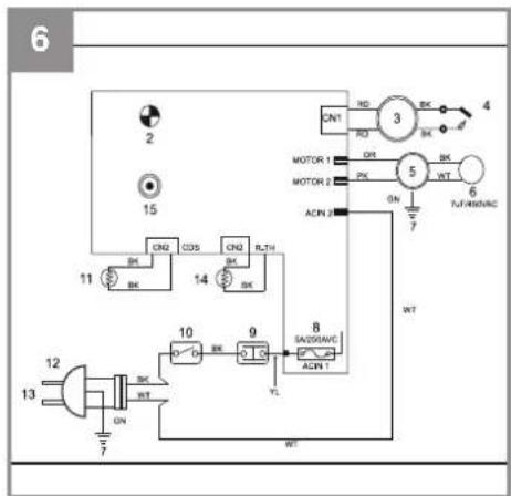

D
Inhaltsverzeichnis
BL = blau, RD = rot, BK = schwarz, WT = weiß, GN = grün, YL = gelb, OR = orange, PK = rosa
- Safety regulations
- Layout and items supplied
- Proper use
- Mode of operation
- Technical data
- Before starting the equipment
- Using the equipment
- Replacing the power cable
- Cleaning, maintenance and ordering of spare parts
- Disposal and recycling
- Troubleshooting
- Circuit diagram (Fig. 6)
- Maintenance by Customer Service
- Troubleshooting information for experts
GB

Danger! - Read the operating instructions to reduce the risk of injury
GB
Danger!
When using the equipment, a few safety precautions must be observed to avoid injuries and damage. Please read the complete operating instructions and safety regulations with due care. Keep this manual in a safe place, so that the information is available at all times. If you give the equipment to any other person, hand over these operating instructions and safety regulations as well. We cannot accept any liability for damage or accidents which arise due to a failure to follow these instructions and the safety instructions.
1. Safety regulations
Danger!
Read all safety regulations and instructions.
Any errors made in following the safety regulations and instructions may result in an electric shock, fi re and/or serious injury.
Keep all safety regulations and instructions in a safe place for future use.
- Read and familiarize yourself with the instructions, especially the safety instructions, before you install this equipment and start to use it. Be aware of the potential dangers associated with the use of oil-filled heaters due to heat, risk of fire, poor ventilation and the handling of fuels.
- No modifications are allowed to be made to the hot air generator.
- Only original parts are allowed to be used for maintenance and accessories.
• Children must be kept away from the hot air generator. - Important: Risk of burns. Do not touch the heating equipment during operation (Fig. 14).
- Never operate the hot air generator in non-ventilated rooms.
- Risk of explosion: Never operate the hot air generator in rooms with combustible materials.
- The pump pressure preset by the manufacturer is not allowed to be changed. The hot air generator could be damaged and/or fires might result.
- Secure the hot air generator against shifting and toppling during transport.
- Place the hot air generator in a secure, level position. Do not turn, tip or change the position of the equipment during operation.
• Always switch off the hot air generator during
transportation and refueling.
- When you refuel the hot air generator, make sure that no fuel is spilt.
- Never operate the hot air generator in rain or snow.
- Never touch the hot air generator with wet hands.
- Protect yourself against electric hazards. Use an extension cable outdoors only if is approved for outdoor duty and is marked accordingly.
- The overall length of extension cables is not allowed to exceed 50 m for 1.5 mm ^2 and 100 m for 2.5 mm ^2 .
- Leave repairs and adjustment work strictly to authorized trained personnel.
- Do not refuel or empty the tank near open lights, fire or sparks. Do not smoke!
- Do not touch any hot parts. Do not remove any safety guards.
- Do not expose the equipment to damp or dust. Permissible ambient temperature - 10 to +40 °C, max. altitude above sea level 1000 m, relative humidity 90% (non-condensing).
- Important! Diesel fuel and EL heating oil are harmful to your health. Use protective gloves when working with diesel fuel or EL heating oil. Make sure that working materials (cloths, rags) which are impregnated with diesel fuel or EL heating oil are disposed of properly.
- Never connect the hot air generator to external fuel tanks.
• Use the machine only if it is fully assembled.
- Pull out the power plug when the equipment is not in use.
- Never cover the air inlet or air outlet openings – risk of fire.
- Never transport the equipment when it contains fuel.
- The minimum distance between the equipment and other objects is 3 m to the front and 1.25 m to the rear, side and top. Be sure to observe the minimum distance.
- Use the equipment only outdoors or in well-ventilated rooms. The room must have air inlet openings of at least 0.02m^2/kW heat output. For a heat output of 36kW this means openings with a total size of 0.72m^2 . You must open for example windows and doors which lead outdoors. The minimum room size must be 1100m^3 .
- Warning! Small amounts of carbon monoxide are produced during combustion.
- Constant ventilation is essential therefore in order to prevent potentially fatal carbon
GB
monoxide poisoning. Symptoms of imminent carbon monoxide poisoning are headache, a burning sensation in the nose and eyes, nausea, dizziness, a dry mouth and a sore throat.
- If the previously mentioned symptoms arise in spite of sufficient ventilation, switch off the equipment at once and open all the windows and doors. Do not use the equipment anymore and send it to Customer Service for inspection.
- Persons with disorders of the bronchial system, lungs or heart, seriously ill persons and pregnant women should seek medical advice before using the equipment.
• Install and ignite in strict adherence to the instructions. - If the equipment cannot be left in a safe condition to run unattended, switch it off.
This equipment is not designed to be used by people (including children) with limited physical, sensory or mental capacities or those with no experience and/or knowledge unless they are supervised by a person who is responsible for their safety or they have received instructions from such a person in how to use the equipment safely. Children must always be supervised in order to ensure that they do not play with the equipment.
Important: Use only diesel or EL heating oil as fuel.
Never use gasoline, white spirit, solvent or any other highly infl ammable substances.
Packaging:
The equipment is supplied in packaging to prevent it from being damaged in transit. Retain the packaging for later storage of the equipment. If you should nevertheless wish to dispose of the packaging, remember that it is raw material and can therefore be reused or can be returned to the raw material system.
2. Layout and items supplied
2.1 Layout (Fig. 1)
- Air outlet opening
- Front handle bar
- Bracket for extension cable
- Top half of the housing
- Temperature indicator
- Rear handle bar
-
Fan cover
-
Pressure indicator
-
Fuel tank
- Drain plug
- Power cable
- ON/OFF switch
- Thermostat adjustment knob
- LED
- Side cover
- Tank cover
- Tank indicator
- Bottom half of the housing
2.2 Items supplied
Please check that the article is complete as specified in the scope of delivery. If parts are missing, please contact our service center or the sales outlet where you made your purchase at the latest within 5 working days after purchasing the product and upon presentation of a valid bill of purchase. Also, refer to the warranty table in the service information at the end of the operating instructions.
- Open the packaging and take out the equipment with care.
- Remove the packaging material and any packaging and/or transportation braces (if available).
• Check to see if all items are supplied. - Inspect the equipment and accessories for transport damage.
- If possible, please keep the packaging until the end of the guarantee period.
Danger!
The equipment and packaging material are not toys. Do not let children play with plastic bags, foils or small parts. There is a danger of swallowing or suff ocating!
• Diesel hot air generator
- Wheels
• Wheel axle (stuck to the box padding)
• Tubular frame (3-piece)
- Spare fuses
• Bag with assembly materials
• Original operating instructions
3. Proper use
The transportable hot air generator, which is powered by EL heating oil or diesel fuel, is ideal for heating and drying well ventilated enclosed spaces (e.g. tents, storage facilities, building
GB
sites) that are of a suitable size (min. 1100 m ^3 ). Adequate ventilation openings must be available to ensure a reliable supply of fresh air and removal of combustion gas. In the open air the equipment is only allowed to be used in areas that are roofed over and protected from the weather.
It is not allowed to be used for heating apartments or in leisure vehicles (e.g. caravans or motor homes).
The equipment is to be used only for its prescribed purpose. Any other use is deemed to be a case of misuse. The user / operator and not the manufacturer will be liable for any damage or injuries of any kind caused as a result of this.
Please note that our equipment has not been designed for use in commercial, trade or industrial applications. Our warranty will be voided if the machine is used in commercial, trade or industrial businesses or for equivalent purposes.
4. Mode of operation
The hot air generator is equipped with a compressor which creates a vacuum in order to draw fuel out of the tank. The drawn fuel arrives at a burner nozzle where an air/fuel mix is formed.
The air/fuel mix is ignited electrically in the combustion chamber. Air is blown into the combustion chamber by the fan and leaves the chamber at the front as hot air. The required temperature can be set with the thermostat knob. When this temperature is reached, the equipment will be switched off automatically. When the temperature drops below the set temperature, the equipment will be switched on again.
A photocell constantly monitors the combustion and will switch off the equipment if any irregularities occur.
The equipment will also be switched off if it overheats. In this case, please contact Customer Service. The electrical components are protected by a miniature fuse.
5. Technical data
Mains connection: 230 V \~ 50Hz / 2.3A
Heat output (Hi): 36 kW
Heat settings: 1
Fuel: EL heating oil or diesel
Pump pressure (+/- 10%): .....0.31 bar (4.2 PSI)
Fuel consumption: 3.6 l/h
Tank capacity: 381
Motor rating: 150W
Max. power consumption: 530 W
Air throughput: 900m³/h
Max. air temperature: 404 °C
Approx. equipment dimensions: ..99 x 58 x 66 cm
Approx. equipment weight: 24 kg
6. Before starting the equipment
- Before you connect the equipment to the power supply, make sure that the data on the rating plate are identical to the supply voltage.
• Always place the portable equipment on a firm, horizontal surface.
- The equipment must always be in a horizontal position.
- The minimum distance between the equipment and other objects is 3 m to the front and 1.25 m to the rear, side and top. Be sure to observe the minimum distance.
- Use the equipment only outdoors or in well-ventilated rooms. The room must have air inlet openings of 0.02 m ^2 per kW heat output. For a heat output of 36 kW this means openings with a total size of 0.72 m ^2 . You must open for example windows and doors which lead outdoors.
- Connect the equipment to an earthed socket outlet only.
- This equipment must be installed and operated in accordance with the regulations in force.
6.1 Assembly (Fig. 2)
You will require the following tools for assembly and installation: Crosstip screwdriver, 8 mm + 19 mm open-ended spanner.
-
Push the wheel axle (C) through the axle mount of the base frame (I). Push the spacer sleeves (D) onto the wheel axle (C).
-
Push the wheels (B) onto the wheel axle.
-
Screw the cap nuts (H) to the axle by hand
GB
(do not tighten them).
- Screw the diesel hot air generator (A) to the front handle bar (2) and the base frame (I). Use the short screws (K), the long screws (L) and the nuts (M).
- Screw the rear handle bar (6) to the base frame with the remaining long screws (L) and nuts (M).
- Remove the wheels again.
- Screw the rear handle bar (6) to the base frame with the remaining short screws (K) and nuts (M).
- Now fully tighten the wheels.
6.2 Fuelling
Note:
- Store the required EL heating oil or diesel fuel in a suitable fuel canister which is clearly labeled with the words "EL Heating Oil" or "Diesel".
- Follow the regulations in force in your country for the storage of EL heating oil and diesel.
- Do not use "bio diesel" under any circumstances.
- At temperatures below 5°C we recommend the use of winter diesel in order to avoid problems with fuel intake.
- EL heating oil and diesel are subject to ageing. Supplies should be used within 6 months.
-
Refuel only outdoors and with equipment which has cooled down.
• Follow the safety information (section 1). -
Remove the tank lid (Fig. 1 / Item 17).
- Slowly fi II EL heating oil or diesel into the tank until the tank indicator (Fig. 1 / Item 18) indicates "F". (For maximum tank capacity see Technical Data.)
- Refi t the tank lid.
7. Using the equipment
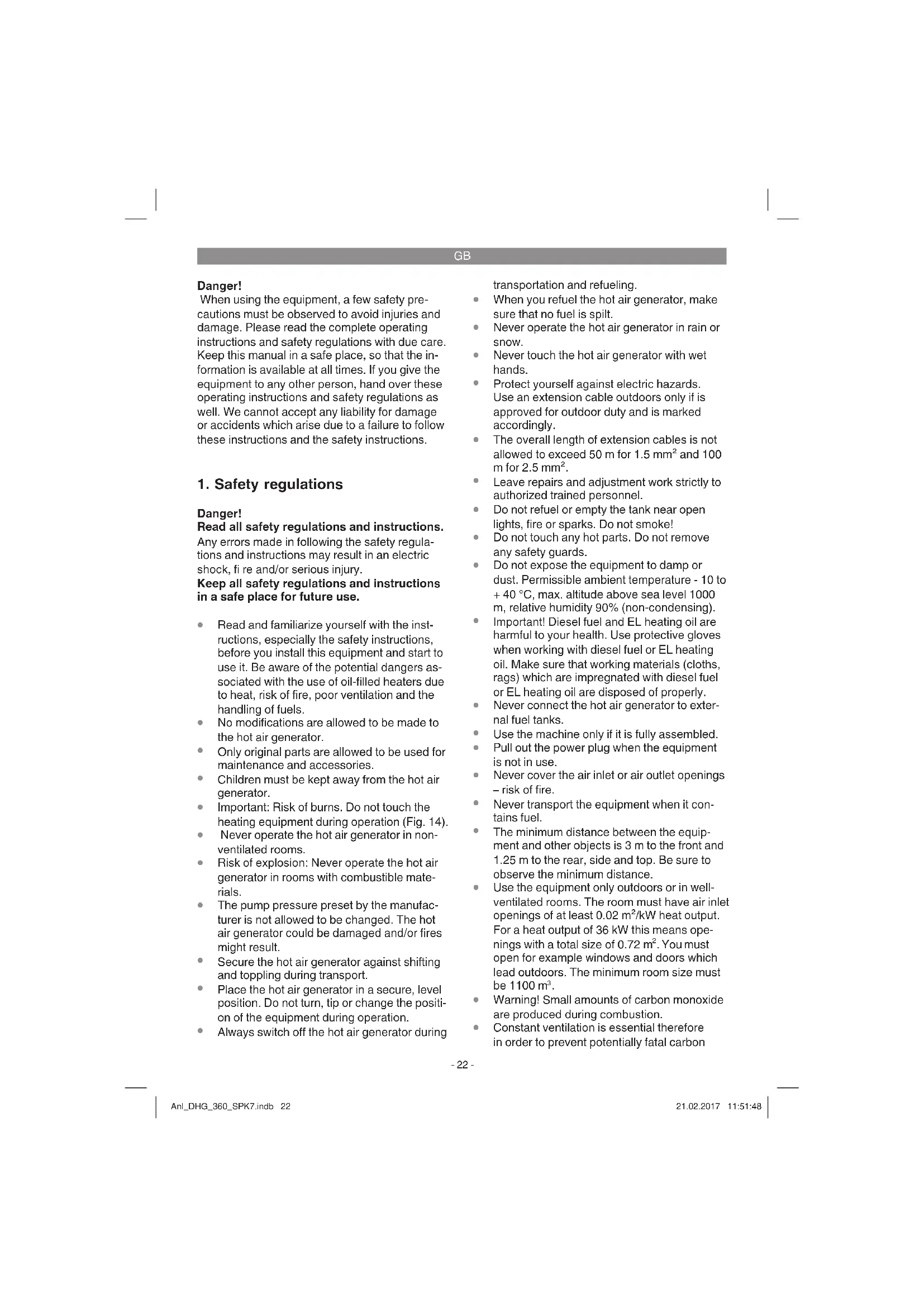
7.1 Switching on (Fig. 3)
Notes:
- The hot air generator can be connected to any shock-proof socket with 230 V AC and a 10 A circuit-breaker. We recommend that you connect the machine only to a power supply which is protected by means of an earth-leakage circuit breaker (RCD) with a maximum trip current of 30 mA.
- Please only use power cables that are not
damaged. There is a limit to how long power cables can be (max. 50m). The power cable must have a cross-section of 3 × 1.5 mm^2 .
- We recommend that you go outdoors to start up the equipment for the first time (this will take approx. 10 minutes) so that any oil residues remaining on the sheet metal parts after production can be burnt off.
- Connect the power plug to an extension cable.
- Use the thermostat knob (Item 14) to set the desired temperature (range + 5 °C to + 45 °C).
- Set the ON/OFF switch (Item 13) to position ON (I) – the equipment will start, the LED (Item 15) will light up and the room temperature will be indicated (Item 5).
Notes:
- The temperature indicator works only in the range from -17 °C to +37 °C. At temperatures below -17°C the indicator will show "LO", at temperatures above +37 °C it will show "HI".
- If the firing does not switch on, the thermostat must be adjusted to a higher temperature. If, contrary to expectations, the heating still fails to switch on, switch off the equipment and check it against the error list (section 11)
7.2 Switching off
- Set the ON/OFF switch (Fig. 3/Item 13) to the OFF (0) position – the equipment will switch off.
- Pull out the power plug.
7.3 Switching on again
- Wait at least 10 seconds before switching on again.
- Switch on the equipment again as described in 7.1 and follow all the previous notes.
7.4 What to do in an emergency
- Immediately switch the ON/OFF switch to the "0" position and unplug the equipment from the mains power.
• Get people away from the danger zone.
GB
8. Replacing the power cable
Danger!
If the power cable for this equipment is damaged, it must be replaced by the manufacturer or its after-sales service or similarly trained personnel to avoid danger.
9. Cleaning, maintenance and ordering of spare parts
Danger!
Always pull out the mains power plug before starting any cleaning work.
9.1 Cleaning
- Keep all safety devices, air vents and the motor housing free of dirt and dust as far as possible. Wipe the equipment with a clean cloth or blow it with compressed air at low pressure.
• We recommend that you clean the device immediately each time you have finished using it. - Clean the equipment regularly with a moist cloth. Do not use cleaning agents or solvents; these could attack the plastic parts of the equipment. Ensure that no water can seep into the device. The ingress of water into an electric tool increases the risk of an electric shock.
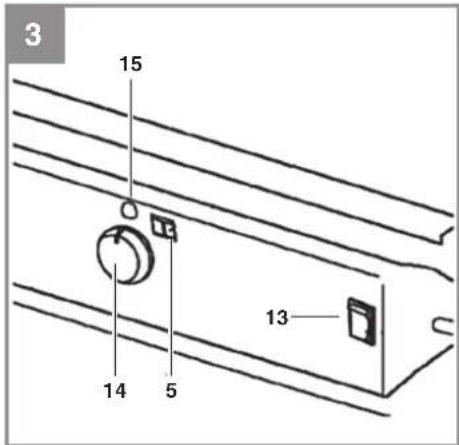
9.2 At the end of the season and before long breaks in operation (Fig. 4)
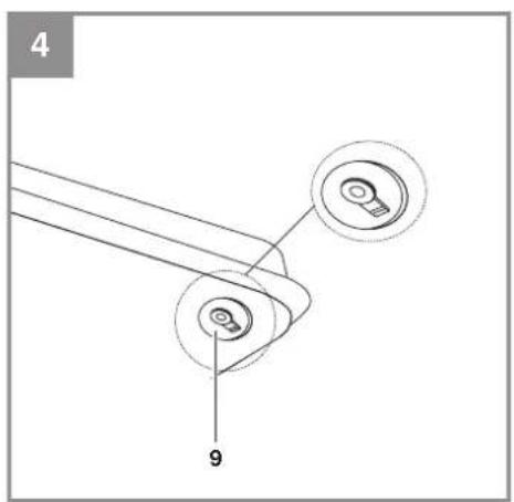
Empty the fuel tank via the drain plug (9) on the bottom of the tank by pulling the plug cover in downwards direction. Collect the old oil in a container and dispose of it in accordance with the regulations in force. If the drain plug is damaged, be sure to replace it. Press the new plug into the tank drain hole and close it with the plug cover (see Fig. 5). Store the equipment and accessories out of children's reach in a dark and dry place at above freezing temperature. The ideal storage temperature is between 5 und 30 °C.
9.3 Servicing
Servicing work may be carried out only by specially trained personnel. Please contact Customer Service.
9.4 Ordering replacement parts:
Please provide the following information on all orders for spare parts:
• Equipment model/type
• Equipment article number
• Equipment ID number
- Spare part number of the required spare part For our latest prices and information please go to www.isc-gmbh.info
10. Disposal and recycling
The equipment is supplied in packaging to prevent it from being damaged in transit. The raw materials in this packaging can be reused or recycled.
The equipment and its accessories are made of various types of material, such as metal and plastic. Defective components must be disposed of as special waste. Ask your dealer or your local council.
11. Troubleshooting
If the equipment is operated properly you should experience no problems with malfunctions or faults. In the event of any malfunctions or faults, please check the following before you contact your customer services.
Fault
The fan motor does not start up, the LED is off.
Possible cause
a) Power failure.
b) The power cable or the power cable is damaged.
c) The safety temperature limiter switches on.
d) Defective miniature fuse.
Remedy
a) Check the voltage, if necessary wait for re-start.
b) Have repairs carried out by a specialized company.
c) Establish the cause of the overheating. Go not cover the air inlet/outlet channels.
Wait for at least 10 minutes until the equipment has cooled down, then restart. If necessary, contact Customer Service.
d) Replace the miniature fuse.
GB
Fault
The fan motor does not start up, the LED is lit or fl ashes, "E1" or "E2" appears in the display.
Cause
The thermostat is set too low.
Remedy
Set the thermostat to a higher temperature.
Fault
The fan motor is running, the flame does not ignite, the equipment is switched off after several seconds and the LED fl ashes. "E1" appears in the display.
Possible cause
a) There is too little fuel, the wrong fuel or dirty fuel in the tank.
b) The viscosity is too high because the temperature is too low.
Remedy
a) Check the tank contents; slowly fill in clean EL heating oil or diesel.
b) Use winter diesel.
12. Circuit diagram (Fig. 6)
1 Control panel
2 Operating lamp
3 Ignition unit
4 Ignition electrode
5 Pump
6 Capacitor
7 Ground
8 Fuse
9 Monitoring system
10 On/Off switch
11 Photocell
12/13 Power cable with plug
14 Temperature sensor
15 Thermostat
BL = blue, RD = red, BK = black, WT = white, GN
= green, YL = yellow, OR = orange, PK = pink
13. Maintenance by Customer Service
The following maintenance jobs are allowed to be carried out only by specially trained personnel.
- Pull out the power plug before doing any cleaning and maintenance work on the equipment.
- Allow the equipment to cool down completely before you start with the maintenance work.
• Beware of sharp edges. - For safety reasons, use only original spare parts.
- Poor maintenance can result in higher exhaust values, soot, malfunctions and damage to the equipment.
We recommend that the maintenance jobs be performed in the intervals stated:
Fuel tank
The fuel tank must be rinsed out with clean fuel after every 200 hours in operation or when necessary. Never use water!
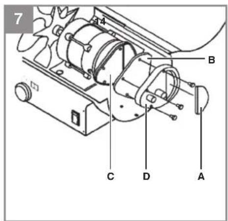
Air fi Iter (Fig. 7)
The air intake fi Iter (A) must be replaced or cleaned with soapy water after every 500 hours in operation or sooner if necessary. Allow the air intake fi Iter to dry after it has been cleaned.
The two air discharge fi Iters (B / C) must be replaced after every 500 hours in operation or sooner if necessary. Unscrew the fi Iter cover (D) for this purpose.
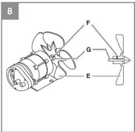
Fan blades (Fig. 8)
The fan blades (E) must be cleaned at least once every heating season or more often if necessary. Remove the dust and other dirt with a soft cloth. Make sure that the fan blades are not bent. To replace the fan blades, undo the screw (F) and pull the fan blade off the motor shaft (G).
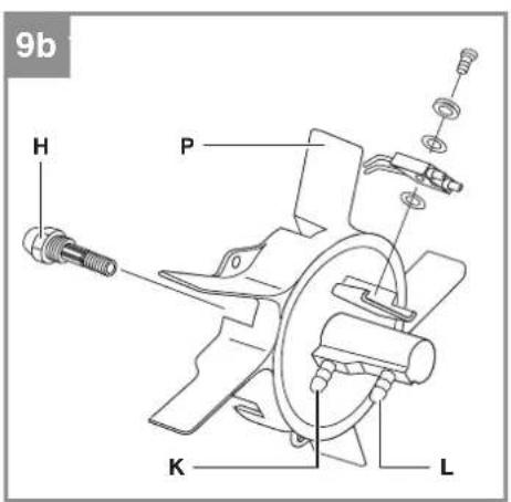
The fuel nozzle (H) must be cleaned or replaced at least once every heating season or more often if necessary.
Clean the fuel nozzle from the front with compressed air. To remove stubborn dirt, it can help to saturate the fuel nozzle in clean fuel and wash it out. Take care not to swap the two hoses (K/L).
GB
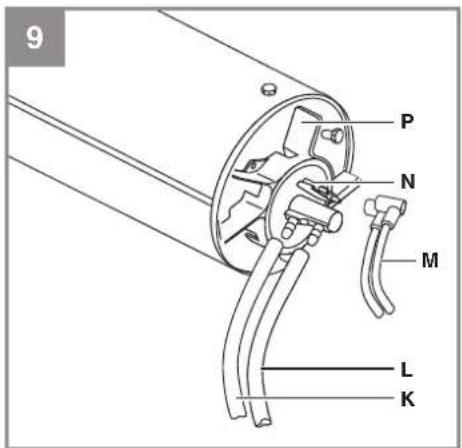
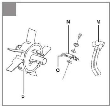
Legend for the items in Figure 9a/9b:
Item K = air hose (connection) Item L = fuel hose (connection) Item M = ignition cable Item N = ignition electrode Item P = burner head
Ignition electrode (Fig. 10)
The ignition electrode (N) must be cleaned or replaced after every 600 hours in operation or sooner if necessary. Clean the ignition contacts (Q) carefully with a wire brush. Check the distance between the ignition contacts (Q). It must be 3.5mm .
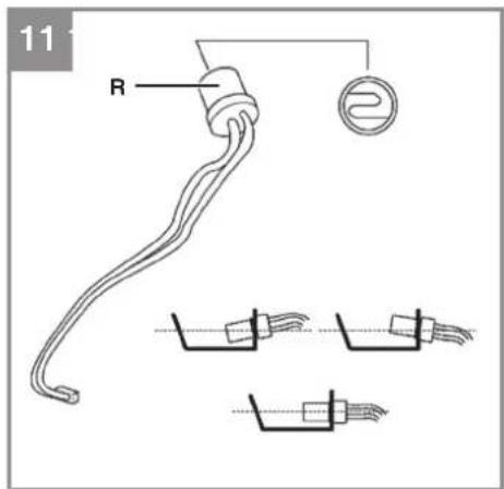
Photocell (Fig. 11)
The photocell (R) must be cleaned or replaced at least once every heating season or more often if necessary. Clean the front of the photocell with a cotton cloth which has been saturated in alcohol. When you insert the photocell, make sure it is correctly positioned.
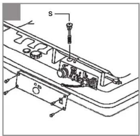
Fuel fi Iter (Fig. 12)
Clean or replace the fuel fi liter (S) at least twice every heating season or more often if necessary. The fuel fi liter must be washed out with clean fuel. Note: To undo the fuel fi liter, turn it 90^ in counterclockwise direction.
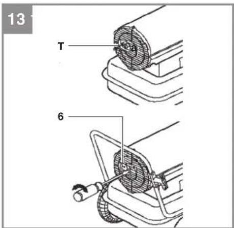
Setting the pump pressure (Fig. 13)
The optimum pump pressure is quoted in the technical data. While the equipment is working, use a screwdriver to turn the setting screw (T) until the pressure gauge (Item 8) indicates the optimum pump pressure. Turning it clockwise will increase the pressure, turning it counter-clockwise will decrease the pressure.
14. Troubleshooting information for experts
Problem
The flame ignites but after a short while the heater switches off, the LED flashes and "E1" appears in the display.
Possible cause
- The pump pressure is not correct.
- Soiled air fi Iters.
- Soiled fuel fi Iter.
- Soiled fuel nozzle.
-
Soiled photocell.
-
Photocell not fitted correctly.
- Photocell is defective.
- Poor electrical connection between the pcb and the photocell.
Remedy
- Adjust the pump pressure.
- Clean or replace the air filters.
- Clean or replace the fuel filter.
- Clean or replace the fuel nozzle.
- Clean or replace the photocell.
- Adjust the photocell correctly.
- Replace the photocell.
- Check the electrical connection between the pcb and the photocell.
Problem
The heater does not work at all or the fan motor runs for only a short while. The LED flashes and "E1" appears in the display.
Possible cause
- No fuel in the tank.
- The pump pressure is not correct.
- Corroded ignition electrode or wrong distance
between the ignition contacts. - Soiled fuel fi Iter.
- Soiled fuel nozzle.
- Moisture / water in the fuel or fuel tank.
- Poor electrical connection between the transformer and the pcb.
- Ignition cable is not connected to the ignition electrode.
- Ignition electrode is defective.
Remedy
- Fill fuel into the tank.
- Adjust the pump pressure.
- Clean or replace the ignition electrode.
- Clean or replace the fuel filter.
- Clean or replace the fuel nozzle.
- Clean the tank, fill in fresh fuel.
- Check all electrical connections.
- Connect the ignition cable to the ignition electrode.
- Replace the ignition electrode.
Problem
The fan motor does not switch on. The mains voltage is active and the ON/OFF switch is set to ON (I).
The LED is lit or fl ashes and "E1" or "E2" appears in the display.
GB
Possible cause
- The thermostat is set to too low a temperature.
- The electrical connection between the pcb and the motor is interrupted.
necessary.
- Check all electrical connections.
Remedy
- Set the thermostat knob to a higher temperature.
- Check all electrical connections.
Problem
The LED fl ashes and "E3" appears in the display.
Possible cause
The thermostat switch is defective.
Remedy
Replace the thermostat switch.
Problem
Poor combustion and / or formation of soot.
Possible cause
- Flames emerge from the front of the housing.
- Too low a heat output.
- Poor fuel quality.
- Generally poor maintenance.
Remedy
- Reduce the pump pressure.
- Increase the pump pressure.
- Check whether old or dirty fuel is being used.
- Have the equipment serviced by specialized personnel.
Problem
The heater does not switch and on the LED does not light up.
Possible cause
- The equipment is overheated and therefore the safety temperature limiter has responded.
- No mains voltage.
- Defective miniature fuses.
- Connection between the thermostat and the pcb has been interrupted.
Remedy
- Set the ON/OFF switch to OFF (0) and allow the heater to cool for at least 10 minutes.
Then set the On/Off switch back to ON (I). - Check the socket-outlet, the power cable and the extension cable.
- Check the miniature fuse and replace it if
GB

For EU countries only
Never place any electric power tools in your household refuse.
To comply with European Directive 2012/19/EC concerning old electric and electronic equipment and its implementation in national laws, old electric power tools have to be separated from other waste and disposed of in an environment-friendly fashion, e.g. by taking to a recycling depot.
Recycling alternative to the return request:
As an alternative to returning the equipment to the manufacturer, the owner of the electrical equipment must make sure that the equipment is properly disposed of if he no longer wants to keep the equipment. The old equipment can be returned to a suitable collection point that will dispose of the equipment in accordance with the national recycling and waste disposal regulations. This does not apply to any accessories or aids without electrical components supplied with the old equipment.
The reprinting or reproduction by any other means, in whole or in part, of documentation and papers accompanying products is permitted only with the express consent of the iSC GmbH.
Subject to technical changes
GB
Service information
We have competent service partners in all countries named on the guarantee certificate whose contact details can also be found on the guarantee certificate. These partners will help you with all service requests such as repairs, spare and wearing part orders or the purchase of consumables.
Please note that the following parts of this product are subject to normal or natural wear and that the following parts are therefore also required for use as consumables.
| Category Example | |
| Wear parts* Fuses, fi Iters | |
| Consumables* | |
| Missing parts |
* Not necessarily included in the scope of delivery!
In the effect of defects or faults, please register the problem on the internet at www.isc-gmbh.info. Please ensure that you provide a precise description of the problem and answer the following questions in all cases:
• Did the equipment work at all or was it defective from the beginning?
• Did you notice anything (symptom or defect) prior to the failure?
• What malfunction does the equipment have in your opinion (main symptom)?
Describe this malfunction.
GB
Warranty certifi cate
Dear Customer,
All of our products undergo strict quality checks to ensure that they reach you in perfect condition. In the unlikely event that your device develops a fault, please contact our service department at the address shown on this guarantee card. You can also contact us by telephone using the service number shown. Please note the following terms under which guarantee claims can be made:
- These guarantee terms apply to consumers only, i.e. natural persons intending to use this product neither for their commercial activities nor for any other self-employed activities. These warranty terms regulate additional warranty services, which the manufacturer mentioned below promises to buyers of its new products in addition to their statutory rights of guarantee. Your statutory guarantee claims are not affected by this guarantee. Our guarantee is free of charge to you.
- The warranty services cover only defects due to material or manufacturing faults on a product which you have bought from the manufacturer mentioned below and are limited to either the rectification of said defects on the product or the replacement of the product, whichever we prefer. Please note that our devices are not designed for use in commercial, trade or professional applications. A guarantee contract will not be created if the device has been used by commercial, trade or industrial business or has been exposed to similar stresses during the guarantee period.
-
The following are not covered by our guarantee:
-
Damage to the device caused by a failure to follow the assembly instructions or due to incorrect installation, a failure to follow the operating instructions (for example connecting it to an incorrect mains voltage or current type) or a failure to follow the maintenance and safety instructions or by exposing the device to abnormal environmental conditions or by lack of care and maintenance.
- Damage to the device caused by abuse or incorrect use (for example overloading the device or the use or unapproved tools or accessories), ingress of foreign bodies into the device (such as sand, stones or dust, transport damage), the use of force or damage caused by external forces (for example by dropping it).
-
Damage to the device or parts of the device caused by normal or natural wear or tear or by normal use of the device.
-
The guarantee is valid for a period of 24 months starting from the purchase date of the device. Guarantee claims should be submitted before the end of the guarantee period within two weeks of the defect being noticed. No guarantee claims will be accepted after the end of the guarantee period. The original guarantee period remains applicable to the device even if repairs are carried out or parts are replaced. In such cases, the work performed or parts fitted will not result in an extension of the guarantee period, and no new guarantee will become active for the work performed or parts fitted. This also applies if an on-site service is used.
-
To make a claim under the guarantee, please register the defective device at: www.isc-gmbh.info. Please keep your bill of purchase or other proof of purchase for the new device. Devices that are returned without proof of purchase or without a rating plate shall not be covered by the guarantee, because appropriate identification will not be possible. If the defect is covered by our guarantee, then the item in question will either be repaired immediately and returned to you or we will send you a new replacement.
Of course, we are also happy offer a chargeable repair service for any defects which are not covered by the scope of this guarantee or for units which are no longer covered. To take advantage of this service, please send the device to our service address.
Also refer to the restrictions of this warranty concerning wear parts, consumables and missing parts as set out in the service information in these operating instructions.
F
Sommaire
BL = blå, RD = röd, BK = svart, WT = vit, GN = grön, YL = gul, OR = orange, PK = rosa
Snaga grejača (Hi): 36 kW
Stepeni grejanja: 1
Gorivo: ....lož ulje ili dizel
Pritisak u pumpi (+/- 10%): .....0,31 bara (4,2 PSI)
Potrošnja goriva: 3,6 l/h
Sadržaj rezervoara: 38 l
Snaga motora: 150 W
Snaga maks.: 530 W
Protok vazduha: 900 m³/h
Temperatura vazduha maks.: 404 °C
Dimenzije uređaja cirka: .....99 x 58 x 66 cm
Težina uređaja cirka: 24 kg
6. Pre puštanja u pogon
- Pre priključivanja proverite da li podaci na natpisnoj pločici odgovaraju podacima o mreži.
- Prenosni uređaj uvek postavljajte na stabilnu i horizontalnu podlogu.
- Uređaj mora uvek da bude u horizontalnom položaju.
- Obratite pažnju na to da razmak uređaja od predmeta mora biti najmanje 3 m od napred, 1,25 m s leđne strane, bočno i gore.
- Uređaj treba da se postavi na otvorenom ili u dobro provetrenim prostorijama. Prostorija treba imati otvore za ulaz vazduha veličine 0,02 m² po kW snage grejanja. Kod snage grejača od 36 kW ti otvori imaju ukupnu veličinu od 0,72 m². U tu svrhu otvorite npr. vrata i prozore prema spolja.
- Uređaj priključite samo na uzemljenu mrežnu utičnicu.
- Uređaj mora biti postavljen i korišćen u skladu s važećim propisima.
6.1 Montaža (sl. 2)
Za montažu je potreban: unakrsni odvijač, viljuškasti ključ 8 mm + 19 mm.
- Gurnite osovinu točka (C) kroz prihvatač osnovnog okvira (I). Gurnite distancione čaure (D) na osovinu točka (C).
- Gurnite točkove (B) na osovinu.
- Rukom zavnite (ne prečvrsto) slepe navrtke (H) na osovinu.
- Učvrstite zavrtnjima dizel generator za topli vazduh (A) s prednjom drškom (2) i osnovnim
RS
okvirom (I). Za to upotrebite kratke zavrtnje (K), duge zavrtnje (L) i navrtke (M).
- Pričvrstite stražnju dršku (6) na osnovni okvir preostalim dugim zavrtnjima (L) i navrtkama (M).
- Ponovo skinite točkove.
- Pričvrstite stražnju dršku (6) na osnovni okvir preostalim kratkim zavrtnjima (K) i navrtkama (M).
- Pričvrstite točkove do kraja.
6.2 Punjenje rezervoara
Napomene:
- Potrebno lož ulje EL ili dizel gorivo obavezno treba da se stavi u odgovarajuće kanistre za gorivo s jasnom oznakom „Lož ulje EL“ odnosno „Dizel“.
- Poštujte propise za skladištenje lož ulja EL i dizela koji važe u vašoj zemlji.
• Ni u kom slučaju ne koristite „biodizel“. - Da biste izbegli probleme sa usisavanjem goriva, preporučujemo da kod temperatura nižih od 5 °C koristite zimski dizel.
- Lož ulje EL i dizel gorivo stare. Stoga se preostalo gorivo mora potrošiti u roku od 6 meseci.
- Gorivo sipajte u rezervoar samo na otvorenom i kada je uredaj ohlađen.
-
Poštujte bezbednosne napoemene (poglavlje 1).
-
Skinite poklopac s rezervoara (sl. 1 / poz. 17).
- Polako sipajte lož ulje EL ili dizel do oznake (sl. 1 / poz. 18) „F“ na rezervoaru. (Maks. kapacitet rezervoara v. Tehničke podatke)
- Ponovno montirajte poklopac na rezervoar.
7. Rukovanje
BL = blauw, RD = rood, BK = zwart, WT = wit, GN
= groen, YL = geel, OR = oranje, PK = roze
Subject to change without notice
Archive-File/Record: NAPR015295
Documents registrar: Landauer Josef
Wiesenweg 22, D-94405 Landau/Isar


EH 02/2017 (01)


- D
- Inhaltsverzeichnis
- GB
- Danger!
- Safety regulations
- Important: Use only diesel or EL heating oil as fuel.
- Packaging:
- Layout and items supplied
- Layout (Fig. 1)
- Items supplied
- Proper use
- Mode of operation
- Technical data
- Before starting the equipment
- Assembly (Fig. 2)
- Fuelling
- Note:
- Using the equipment
- Switching on (Fig. 3)
- Notes:
- Switching off
- Switching on again
- What to do in an emergency
- Replacing the power cable
- Cleaning, maintenance and ordering of spare parts
- Cleaning
- At the end of the season and before long breaks in operation (Fig. 4)
- Servicing
- Ordering replacement parts:
- Disposal and recycling
- Troubleshooting
- Fault
- Possible cause
- Remedy
- Cause
- Circuit diagram (Fig. 6)
- Maintenance by Customer Service
- Fuel tank
- Air fi Iter (Fig. 7)
- Fan blades (Fig. 8)
- Legend for the items in Figure 9a/9b:
- Ignition electrode (Fig. 10)
- Photocell (Fig. 11)
- Fuel fi Iter (Fig. 12)
- Setting the pump pressure (Fig. 13)
- Troubleshooting information for experts
- Problem
- Service information
- Warranty certifi cate
- F
- Sommaire
- Pre puštanja u pogon
- Montaža (sl. 2)
- RS
- Punjenje rezervoara
- Napomene:
- Rukovanje
Brand : EINHELL
Model : DHG 360
Category : Heating