Solerio Optimum - Boiler ATLANTIC - Free user manual and instructions
Find the device manual for free Solerio Optimum ATLANTIC in PDF.
| Product type | Combi boiler with domestic hot water storage tank |
| Brand | Atlantic |
| Model | Solerio Optimum |
| Tank capacity (standard models) | 75 L, 100 L, 150 L, 200 L |
| Empty weight (75 L model) | 36 kg |
| Empty weight (100 L model) | 41 kg |
| Empty weight (150 L model) | 55 kg |
| Empty weight (200 L model) | 63 kg |
| Power supply | Single-phase 220-240 V or three-phase 400 V depending on model |
| Anti-corrosion protection | Titanium or magnesium anode depending on model; ACI system on some models |
| Main functions | Domestic hot water production by heat exchange (winter) or electric resistance (summer/1/2 season); possibility of charging pump kit |
| Set temperature | 65 °C (factory setting) |
| Maximum operating pressure | 3 bar for primary circuit; 5 bar for cold water network |
| Maximum temperature | 100 °C |
| Maintenance and cleaning | Operate the drain valve once a month; descaling by qualified personnel; replace magnesium anode every 2 years or if diameter < 10 mm |
| Safety | Safety group EN 1487; manual reset thermal cut-out; 30 mA residual current device recommended |
| Spare parts and repairability | Replaceable parts: thermostat, seals, heating element, anode, ACI, cables, switch; use of original manufacturer parts mandatory for warranty |
| Tank warranty (ACI model) | 5 years (France and Belgium) |
| Warranty on electrical components | 2 years |
| Standards | Compliant with directives 89/336/EEC and 73/23/EEC as amended |
Frequently Asked Questions - Solerio Optimum ATLANTIC
User questions about Solerio Optimum ATLANTIC
0 question about this device. Answer the ones you know or ask your own.
Ask a new question about this device
Download the instructions for your Boiler in PDF format for free! Find your manual Solerio Optimum - ATLANTIC and take your electronic device back in hand. On this page are published all the documents necessary for the use of your device. Solerio Optimum by ATLANTIC.
USER MANUAL Solerio Optimum ATLANTIC
NOTICE "ECHANGEUR OPTIMISE" (DS):
PREPARATEUR EAU CHAUBE SANITAIRE
HANDLEIDING "GEOPTIMALISEERDE WISSELAAR" (DS):
KEUKEN-EN BADBOILER
INSTRUCTIONS "ECHANGEUR OPTIMISE" (DS):
DOMESTIC HEAT EXCHANGER
MANUEL "ECHANGEUR OPTIMISE" (DS) :
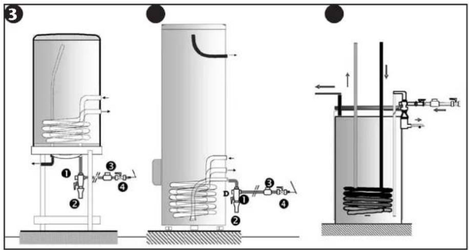
1 Hot water exit
2 Coil entry
3 Coil exit
4 Cold water entry
5 Enamelled coil
6 White steel jacket
7 Enamelled tank
8 Protection cap
9 Magnesium or titanium anode
10CFC-free polyurethane foam
Safety relief valve EN 1487
2Funnel
3 Pressure reducing valve (recommended if pressure>5 bar)
4 Stop valve
3
1Grupo de segurarca EN 1487
Sifao
3 Redutor de pressao (si superior a S bar)
4Tomeira de seguranga
Silkerhedsaggregat EN 1487
Aflabssifon
3 Trykformindsker (hvis tryk > 5 bar)
4 Stopventil
CHAMPS D'APPLICATION DE LA GARANTIE
UW APPARAAT IS WERKINGSKLAAR.
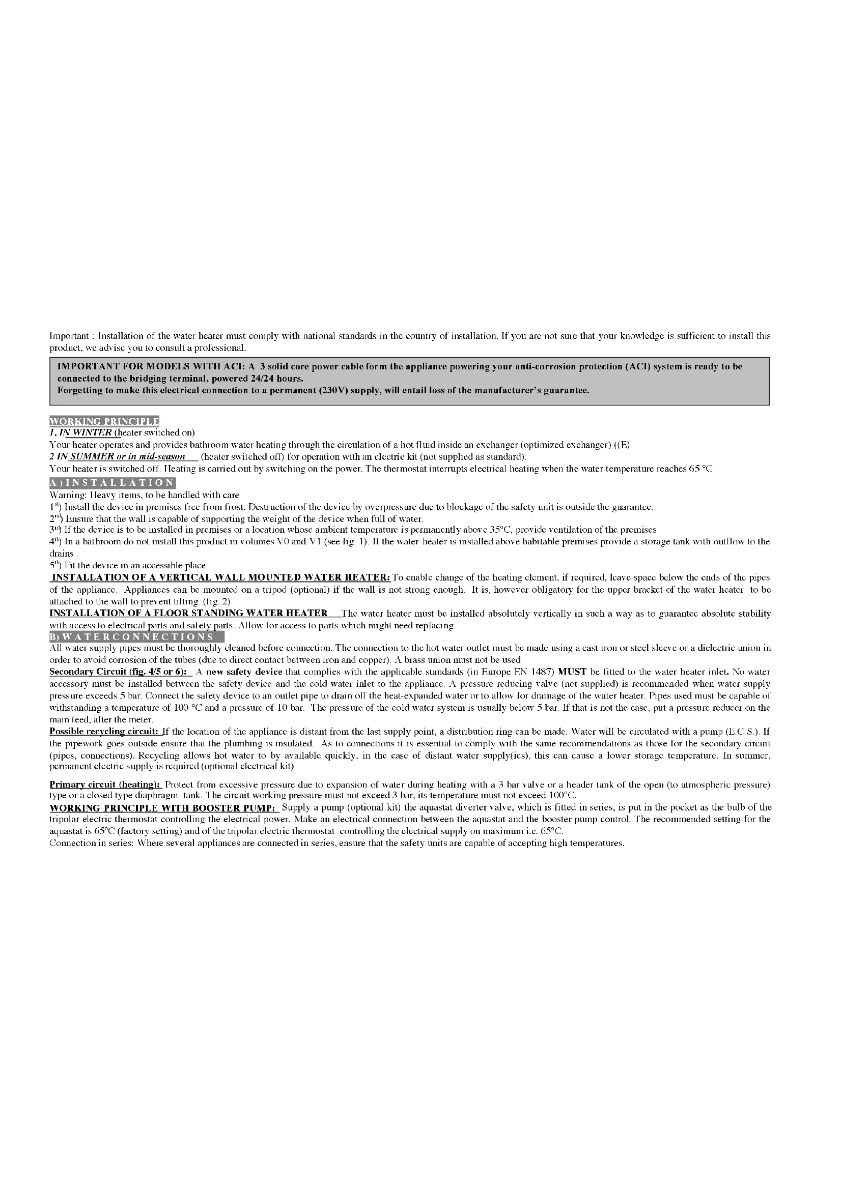
Important : Installation of the water heater must comply with national standards in the country of installation. If you are not sure that your knowledge is sufficient to install this product, we advise you to consult a professional.
IMPORTANT FOR MODELS WITH ACI: A 3 solid core power cable form the appliance powering your anti-corrosion protection (ACI) system is ready to be connected to the bridging terminal, powered 24/24 hours.
Forgetting to make this electrical connection to a permanent (230V) supply, will entail loss of the manufacturer's guarantee.
WORKING PRINCIPLE
- IN WINTER (heater switched on)
Your heater operates and provides bathroom water heating through the circulation of a hot fluid inside an exchanger (optimized exchanger) ((E)
2 IN SUMMER or in mid-season (heater switched off) for operation with an electric kit (not supplied as standard).
Your heater is switched off. Heating is carried out by switching on the power. The thermostat interrupts electrical heating when the water temperature reaches 65^
A) INSTALLATION
Warning: Heavy items, to be handled with care
1) Install the device in premises free from frost. Destruction of the device by overpressure due to blockage of the safety unit is outside the guarantee.
2^nd Ensure that the wall is capable of supporting the weight of the device when full of water.
3^rd If the device is to be installed in premises or a location whose ambient temperature is permanently above 35^ , provide ventilation of the premises
4) In a bathroom do not install this product in volumes V0 and V1 (see fig. 1). If the water-heater is installed above habitable premises provide a storage tank with outflow to the drains.
5^th) Fit the device in an accessible place.
INSTALLATION OF A VERTICAL WALL MOUNTED WATER HEATER: To enable change of the heating element, if required, leave space below the ends of the pipes of the appliance. Appliances can be mounted on a tripod (optional) if the wall is not strong enough. It is, however obligatory for the upper bracket of the water heater to be attached to the wall to prevent tilting. (fig. 2)
INSTALLATION OF A FLOOR STANDING WATER HEATER The water heater must be installed absolutely vertically in such a way as to guarantee absolute stability with access to electrical parts and safety parts. Allow for access to parts which might need replacing.
B) WATERCONNECTIONS
All water supply pipes must be thoroughly cleaned before connection. The connection to the hot water outlet must be made using a cast iron or steel sleeve or a dielectric union in order to avoid corrosion of the tubes (due to direct contact between iron and copper). A brass union must not be used.
Secondary Circuit (fig. 4/5 or 6): A new safety device that complies with the applicable standards (in Europe EN 1487) MUST be fitted to the water heater inlet. No water accessory must be installed between the safety device and the cold water inlet to the appliance. A pressure reducing valve (not supplied) is recommended when water supply pressure exceeds 5 bar. Connect the safety device to an outlet pipe to drain off the heat-expanded water or to allow for drainage of the water heater. Pipes used must be capable of withstanding a temperature of 100^ and a pressure of 10 bar. The pressure of the cold water system is usually below 5 bar. If that is not the case, put a pressure reducer on the main feed, after the meter.
Possible recycling circuit: If the location of the appliance is distant from the last supply point, a distribution ring can be made. Water will be circulated with a pump (E.C.S.). If the pipework goes outside ensure that the plumbing is insulated. As to connections it is essential to comply with the same recommendations as those for the secondary circuit (pipes, connections). Recycling allows hot water to be available quickly, in the case of distant water supply(ies), this can cause a lower storage temperature. In summer, permanent electric supply is required (optional electrical kit)
Primary circuit (heating): Protect from excessive pressure due to expansion of water during heating with a 3 bar valve or a header tank of the open (to atmospheric pressure) type or a closed type diaphragm tank. The circuit working pressure must not exceed 3 bar, its temperature must not exceed 100^ .
WORKING PRINCIPLE WITH BOOSTER PUMP: Supply a pump (optional kit) the aquastat diverter valve, which is fitted in series, is put in the pocket as the bulb of the tripolar electric thermostat controlling the electrical power. Make an electrical connection between the aquastat and the booster pump control. The recommended setting for the aquastat is 65^ (factory setting) and of the tripolar electric thermostat controlling the electrical supply on maximum i.e. 65^ .
Connection in series: Where several appliances are connected in series, ensure that the safety units are capable of accepting high temperatures.
ELECTRICAL CONNECTION (SEE THE TABLE OF DIAGRAMS PAGE AND REFER TO THE RELEVANT DIAGRAMS)
The water heater can be connected and powered only by a single-phase 220 240V AC or a three-phase 400V mains supply according to model. Connect the water heater via a fixed duct with a cross section of 2.5mm^2 . For that, use standard channeling (fixed or fluted conduit) to the calibrated receptacle in the cover. For appliances supplied with a cable or a plug (prohibited in France), connect directly. The earth wire of the cable must be connected to earth or lead the earth wire to the terminal provided indicated by the symbol :
This connection is absolutely necessary for safety reasons. The green yellow earth lead must be longer than the two live wires. Installation must include upstream of the appliance, an all-pole cut-out device (contact opening at least 3mm fuse, breaker switch). Where the water pipes are made of insulating material, the electrical contacts must be protected by a 30~mA earth-leakage breaker conforming to the standards in force. Adapt the connection to the power supply. (see diagrams A1 to F2 and table p. 4)
Thermal circuit breaker: All our mixed products are equipped with a thermostat with thermal circuit breaker with manual resetting which cuts off the power supply to the water heater in case of overheating.
Warning: If the safety trips a) switch off the power before taking any further action, b) remove the cover, c) check the electrical connections, d) reset the thermal circuit breaker. If the circuit breaker keeps tripping, replace the thermostat. Never short circuit the safety cut out or the thermostat. Connect the power supply only via the terminal.
ELECTRICAL CONNECTION. - Optional kits: For the installation and electrical connection of the kits refer to the instruction included with each package. (electrical kit, pump kit) When using a tank for a solar system take not of local legislation. (E.g.: prohibited in Spain)
FOR ACI MODEL WITH CONNECTION OF THE CATHODIC PROTECTION
No other action is required (internal connections are already made).
A 3 solid core power cable form the appliance powering your anti-corrosion protection (ACI) system is ready to be connected to the bridging terminal, with power on 24/24 hours.
After switching on the appliance, check that the green ACT indicator I.F.D on the cover flashes no later than 15 minutes after the appliance is switched on.
SETUP/OPERATION
WARNING: Never switch on the water heater without water.
The secondary circuit must be filled. Before switching on, open the hot water taps, vent the pipes of air and fill the appliance.
Fill the primary circuit (circuit connected to the boiler) Open the water tap, unscrew the air vent to purge air introduced by the filing operation. For an installation fitted with a booster pump, switch it on for a moment or two to speed up dc gassing. Check that the system is full of water, either by checking the level of water in the open header tank, or by opening the vent at the top of the installation.
Check the watertightness of the pipework and the door seal below the cover. In case of a leak, tighten slightly. Check that the water safety devices are working and fill the drain. Switch on the appliance. After 15-30 minutes, depending on the capacity of the appliance, water should drip from the drain hole. This phenomenon is due to water expansion and is normal. Check the watertightness of the joints and the seal. During heating and depending on water quality, room-sealed water heaters can produce a boiling noise; this is normal and does not indicate any defect on the appliance.
To avoid the development of bacteria (legionella...) ensure that a temperature of 60^ is reached every day. The thermostat is set at the factory at the stop (65^ + 5^) .
IMPORTANT: If steam or boiling water emerges continuously from a supply tap or a drain valve, switch off the electricity to the water heater or boiler and call a professional plumbing contractor.
YOUR APPLIANCE IS IN WORKING ORDER
A) IN WINTER: Without electric kit: The domestic water is heated by the primary circuit (thermal exchange). The aquastal diverter valve controls the starting of the booster pump and allows the primary fluid to circulate; it can also be connected to the heating system pump.
B) IN SUMMER OR IN MID-SEASON If you have an electric kit, the boiler being disconnected, domestic hot water will be produce by the electric current.
Cut the power supply linking the pump control thermostat. Turn the switch on the electric panel feeding the thermostat connected to the power supply.
Push the switch "Summer Winter" found on the electrical cover of the heat exchanger tank
If you do not have an electric kit, hot water will be produced by the primary circuit (thermal exchange) - same for winter.
MAINTENANCE
User maintenance: Operate the drain valve on the water safety device once a month. If this is not done, damage may be caused and the guarantee invalidated.
For an installation with a booster pump; before starting up, after a long period of disuse, turn the rotor following the advice in the manufacturer's instructions.
Maintenance by a qualified person:
a) Remove the scale sludge. Do not scrape or hammer the timescale deposited on the casing, as this may damage the lining.
b) Appliance with magnesium anode; Change the magnesium anode every 2 years or when its diameter is lower than 10mm . Changing the shielded heating element or the anode requires the water heater to be drained and the seal changed. Switch off the power and cold water and open the hot water taps before carrying out these operations. Refit the heating element and tighten the screws smoothly (opposite screws in sequence), check for leaks the next day and tighten if required.
REPLACEABLE PARTS the thermostat, seals, heating element, boiler shell, pilot light, the magnesium anode, the ACI plate, the connection cable. The guarantee requires genuine manufacturer's parts to be used.
ADVICE TO THE USER
When the water has a T11 > 20^ , it is recommended that this be treated. When a softener is used, the water hardness must remain above 15^ .
When switching between winter and summer follow the instructions given above, i.e. by stopping circulation of the primary fluid by closing the valve in the system.
Winter operation requires the switching off of the electric power supply (if you have a kit).
In case of prolonged absence, especially in winter, drain your appliance following this procedure.
GUARANTEE APPLICATION AREA
The water heater must be installed, used and maintained according to the best practices and should comply with the applicable standards in the country in which it is installed and to the instructions in this document.
The sales guarantee covers the free exchange of the tanks and components accepted as defective by our after-sales service, except wear and tear parts magnesium anode, seal, etc.) and without indemnity or extension of the guarantee. It does not cover labour or carriage charges, which will be invoiced to you according to our tariffs. It comes into effect on the installation date, authenticated by the sales or installation invoice; in the absence of proof, the date taken into account will be the date of manufacture shown on the indicator plate of the water heater, increased by 6 months. Costs and damage caused by faulty installation (frost, no connection to foul water drain, lack of header tank, etc.) or to difficulty of access, cannot under any circumstances be charged to us. Any claim must be notified to the dealer before exchange under guarantee, and the appliance will remain available to insurance and manufacturer's experts. The provisions of these terms are not exclusive of the profit benefit of the purchaser, of the legal guarantee for faults and hidden defects which apply in any case under the legal conditions of each country.
| Length of sales guarantee: |
| Range ACI Model | Magnesium Model | |
| Tank and heater body 5 years | 3 years | |
| Electrical or other component 2 years | 2 years |
Changing a component does not extend the length of the guarantee. To claim under warranty, contact your installer or dealer. Alternatively, contact the manufacturer who will inform you what steps to take. The guarantee will only apply to products inspected and agreed to be defective by the company liable for the guarantee. The products must be kept available for the latter.
Exclusions from the guarantee: Wear and tear parts: magnesium anodes...Equipment which cannot be assessed (access difficult for repair, maintenance or assessment). Equipment exposed to abnormal environmental conditions: frost, bad weather, abnormally aggressive water or outside drinking standards, unstable electric supply. Equipment not installed in compliance with the applicable standards in the country of installation : the absence or incorrect fitting of safety devices, abnormal corrosion due to incorrect water fitments (iron copper contact), incorrect carthing, inadequate cable thickness, non observance of the connection drawings shown in these instructions. Equipment not maintained in accordance with these instructions. Repairs or replacement of parts or components in the equipment not carried out or authorized by the company responsible for the guarantee. Non-connection of the ACI device for equipment fitted with this equipment. Changing a component does not extend the length of the guarantee.
The products illustrated in these instructions may be modified at any time to reflect changes in manufacture and current norms. Equipment conforms to electromagnetic directives
89.336 CEE and low voltage 73.23 CEE modified by directive 93.68 CEE