ACI - Boiler ATLANTIC - Free user manual and instructions
Find the device manual for free ACI ATLANTIC in PDF.

| Product type | Electric storage boiler (water heater) |
| Brand | Atlantic |
| Model | ACI |
| Capacity | 50 L to 300 L depending on version |
| Dimensions (example 150 L vertical) | Diameter 530 mm, height 1165 mm |
| Empty weight (example 150 L) | 39 kg |
| Power supply | 230 V single-phase (convertible to 400 V three-phase with optional kit) |
| Power | 1200 W to 3000 W depending on capacity |
| Heating element | Steatite, protected by enamelled sheath |
| Anti-corrosion protection | Impressed current anode (titanium) + enamelled tank |
| Control | Adjustable electronic thermostat, preset to 65°C ± 5°C |
| Operation indicator | Green (ACI protection only) / Orange (heating + protection) |
| Safety | Thermal cut-out, dry-run protection, 7 bar safety valve |
| Safety group | Not supplied, must be installed (EN 1487 standard) |
| Installation | Wall-mounted vertical or horizontal, vertical on base; volume 3 or 2/1 bathroom depending on conditions |
| Electrical connection | Rigid cable 3×2.5 mm² (single-phase) or 4×2.5 mm² (three-phase); earth mandatory |
| Routine maintenance | Regularly operate the safety group; check the indicator |
| Professional maintenance | Every 2 years: descaling, replacement of door gasket, check heating elements |
| Spare parts available | Door gasket, electronic thermostat, heating elements, sheath |
| Warranty | 5 years tank, 2 years removable parts |
Frequently Asked Questions - ACI ATLANTIC
User questions about ACI ATLANTIC
0 question about this device. Answer the ones you know or ask your own.
Ask a new question about this device
Download the instructions for your Boiler in PDF format for free! Find your manual ACI - ATLANTIC and take your electronic device back in hand. On this page are published all the documents necessary for the use of your device. ACI by ATLANTIC.
USER MANUAL ACI ATLANTIC
Installationand user'sinstructions· Guarantee -
ATLANTIC heaters have been well known for their quality and reliability for many years.
You have just purchased an ATLANTIC water heater ; we congratulate and thank you for your good choice.
Foreword
Please read and carefully follow the instructions in this manual, so that you will have a properly installed according to standard practice and optimize the performances of your heater. Keep this manual with the guarantee certificate.
Important
National standards and installation practices should never take precedence over elementary safety rules identified in sections of this manual as being "IMPORTANT".
Function
Electric storage water heaters are designed to supply one or several taps.
They are designed to operate under all price rates, except the ACI (Anti Corrosion Instrument) system which requires either continuous use or an 8 hour off-peak tariff within a 24 hour period.
Whenever water is drawn off, the hot water is replaced by the same quantity of cold water; the water heater is always full of water.
It is normal that the water temperature should drop after you have drawn off a large quantity of water.

To be kept by the heater user
Guarantee period :
- 5 years for the tank for standard 50 to 300L water heaters and their heating elements sheath.
- 2 years for removable equipment: door seal, heating element, thermostat, etc.
- 3 years for the tank of high output water heaters, one year for removable tank accessories.
GARANTIISERTIFIKAAT
Raccordement hydraulique
Water heater description
Example
Vertical, floor-standing water heater with a ceramic element and an "impressed current anode"
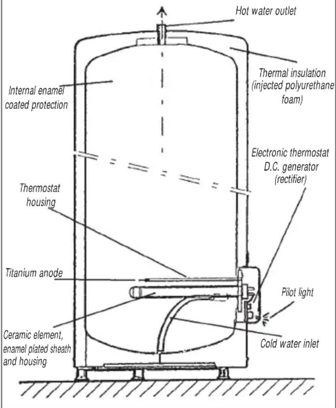
The steel plate tank is designed to resist a pressure that is higher than the working pressure.
Its corrosion protection is provided by a layer of vitrified enamel and an impressed current anode.
The heating element consists of a ceramic element that heats the water inside the tank.
- The ceramic element protected by an enamel-coated sheath, which makes it unnecessary to empty the heater when replacing the element.
The thermostat controls the water temperature.
It is preset in the factory to the "upper stop gauge", about 65^ + / - 5 .
A temperature circuit breaker is provided for safety if the water temperature should rise abnormally.
The tank is protected against corrosion by a very low voltage impressed electrical current.
- The electronic panel permanently provides the necessary current for this protection, both in peak hours and in off-peak hours.
Installation of the heater
IMPORTANT
Put the water heater where it is protected from frost.
- Position it as close as possible to the most frequently used taps.
If it is installed in an uninhabited room (storeroom, cellar, garage) the pipes should be insulated. The continuous ambient temperature around the water heater must not exceed 40^ .
Make sure that the wall-bracket is strong enough to carry the weight of the water heater when full of water.
- Allow 500mm of space in front of each electrical equipment for periodic maintenance of the heating element.
Install a retention tank under the water heater if it is placed inside a false ceiling, in the attic, or above inhabited rooms. An outlet connected to a drainpipe is necessary.
The applicable standards and national regulations on fitting, plumbing and electrical connections must be implemented on installation.
Installing a vertical wall-mounted water heater (VM)
Handles are built into both ends to facilitate handling.
Several attachment types are possible depending on the nature of the wall :
A) Thin walls (plasterboard partition).
10 mm threaded rods passing through the wall connected by sections or plywood panels.
B) Thick hard walls (concrete, stone, brick)
Grout in 10 mm bolts or drill holes to fit 10 mm MOLY type inserts.
C) Vertical wall-mounted water heaters may be placed on a tripod when the partition cannot support the weight of the heater. An additional upper stirrup attachment is compulsory. Use the tripod recommended by the manufacturer.
Use the attachment template printed on the packaging box for both types of walls and check the centre distance of the holes.
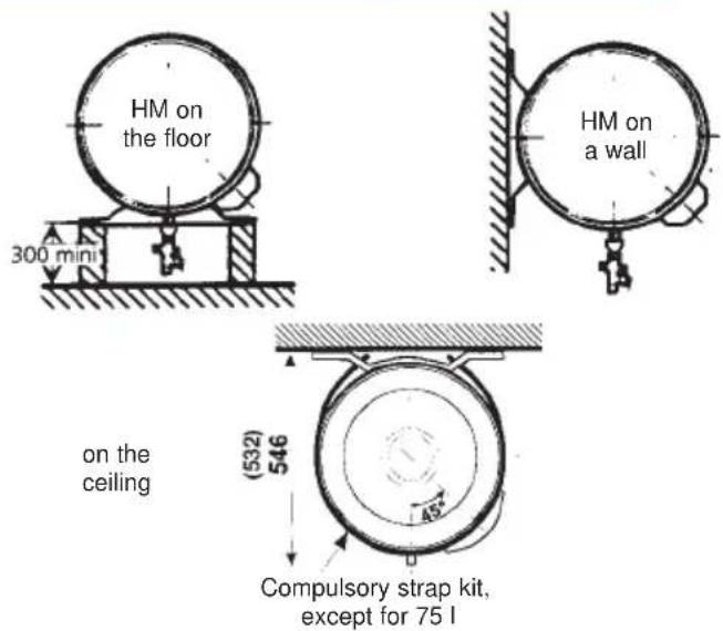
Installing a horizontal wall-mounted water heater (HM)
- Follow the same recommendations as for the vertical wall-mounted water heater. Handles are also provided here.
- IMPERATIVE: For a floor attachment, move the two stirrups and screw them together so that the hydraulic connections are perpendicular to the floor. Provide a minimum packing of 300mm so that the safety unit and drainpipe can be correctly positioned.
For a ceiling attachment the use of the strap kit provided for this purpose (optional accessory) is compulsory; refer to its specific manual.
INSTALLING A VERTICAL WATER HEATER ON A PEDESTAL (VS)
The heater is placed on the ground with shoes fixed under its base. No wall attachment is needed.
A heightening frame may be fixed under the heater to leave space for the pipes (H: 220 mm - optional accessory).
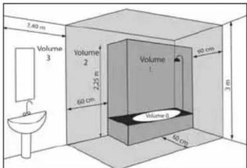
Specific installation for a bathroom (France)
Storage water heaters must be placed in volume 3 and outside the other volumes (NFC 15100).
However, if the dimensions of the bathroom do not allow to place them here, it is possible to install them:
-in volume 2,
- in volume 1, if the water heater is of the horizontal type and placed as high as possible and if the two following conditions are complied with :
- the water pipes are made of conductive material
- the water heater is protected by a differential-residual current circuit breaker set to a maximum of 30mA .
Water connections
Water connections must be made to the water heater in accordance with standards and regulations in force in the country in which it will be installed (for France, use D.T.U. 60.1).
TUBES ON THE HEATER
Each tube is a 20/27 (50 L to 300 L) steel pipe with gas pitch threaded end.
The cold water inlet is marked by a blue collar, and the hot water outlet is marked by a red collar.
Red and blue end pieces are inserted in the connecting tubes and must be kept when connecting to the pipes.
CONNECTIONS TO TUBING
The nature of the connecting tubes may be rigid, usually copper (black steel is prohibited) or flexible (standard flexible stainless steel braid).
- If copper pipes are used, the connection to the hot water outlet must be made using a cast iron or steel coupling, or an insulating connector in order to prevent corrosion of the tubes (direct steel-copper contact). The use of brass fittings is prohibited in this location.
- The connecting tubes must be sealed while installing the water heater (flax fibre, etc.), even if crosslinked PE pipes are used.
- A safety unit (not supplied with the water heater) in conformity with standard EN 1487 shall be screwed onto the water heater cold water inlet.
- When using pipes in synthetic materials (PER, etc), it is highly recommended to fit a thermoregulator at the water heater outlet. It will be set according to the performance of the used material.
CONNECTION DIAGRAM
EXAMPLE OF A VERTICAL WALL-MOUNTED WATER HEATER
This safety unit includes:
1 stop valve
1 manual drain valve
1 non-return valve (to prevent water in the water heater from flowing back into the cold water network)
1 safety valve set to 7 bars
1 non-return valve inspection plug
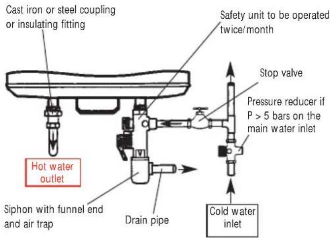
IMPORTANT
The pressure in the cold water network is usually less than 5 bars. If it is not, provide a pressure reducer that will be located on the water inlet after the meter.
ELECTRICAL CONNECTION
Our heaters are in conformity with standards in force and consequently have all necessary safety features. The electrical connection shall comply with installation standard (France) NF C 15-100 and recommendations in force in the country in which the water heater will be installed (Certifying Label, etc.).
The installation shall include :
An omnipole circuit breaker with contacts openings of at least 3mm
A power cable with rigid conductors with a minimum cross-section of 3 × 2.5 mm ≈ in single phase (phase, neutral, earth) or 4 × 2.5 mm ≈ in three-phase (3 phases + earth).
The colour of the earthing conductor shall be green/yellow.
The electronic generator for water heaters with "impressed current anode" has been designed for a permanent power supply or of the type operating in off-peak hours, 8h or 6h + 2h . Make sure that the installation respects one of these two power supply options, the guarantee conditions will not be applicable for shorter off-peak times.
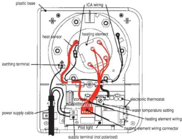
CONNECTION PROCEDURE
- Unscrew the locking screw and remove the protective cover, which contains the electrical connection diagram.
The original connection for this water heater is configured for 230V single phase. For a 400V three-phase connection you need to replace the original single phase plate by a 400V three-phase kit (code 100000). Refer to the manual enclosed with the kit for instructions for installation.
Connect the ends of the thermostat
cables to the screw terminals provided for this purpose (there is no need to disassemble the thermostat).
- Connect the yellow/green earthing wire to the terminal marked with the earthing symbol on the door of the water heater.
Put the cover back after checking that the connection terminals are correctly tightened.
If the temperature needs to be adjusted, refer to the instructions inside the cover.
Put back and tighten the locking screw.
RECOMMENDATIONS
- Provide sufficiently long cables to avoid contact with heating elements.
A direct connection onto a power outlet is prohibited, since the water heater is not equipped with a cable clamp.
An earthing connection is compulsory for safety reasons.
Before making the final connection for the heater, make sure that it is full of water. If not, it is impossible to supply electrical power to the water heater (Dry heating protection).
IMPORTANT
A direct connection to the elements (without passing through the thermostat) is prohibited in all circumstances because it is dangerous, since there is no control over the water temperature anymore.
Start-up
■ FILL THE WATER HEATER
- Open the hot water valve(s).
-
Open the cold water valve on the safety unit (make sure that the heater drain valve is in the closed position).
After water starts to flow through the hot water taps, close them and you water heater is full of water. -
Check that tubing connections are not leaking, and check the door seal under the electrical cover. Retighten it if necessary.
- Check that water control devices are working correctly by turning the safety valve from the drain position to the off position and vice versa, in order to eliminate any waste.
CHECKING CORRECT OPERATION
- Switch the heater on.
- Put the switch on the electrical panel into the forced operation position. After 15 to 30 minutes, water should start dripping through the safety unit drain outlet (which must be connected to a waste water drain pipe).
This phenomenon is normal; it is due to expansion of water due to heating. Consequently, the safety valve will allow a certain amount of water to escape so that internal pressure in the tank does not exceed 7 bars. This flow may be about 2 to
3% of the capacity of the tank when it warms up from cold.
Check the tightness of the connections and the door seal once again.
If the check result is positive and if your electrical panel is equipped with an Offpeak hours (low night rate) servocontrol relay, put the switch to the "automatic" position.
You will see 3 positions in this switch :
- Off or "0" position
- Automatic or "AUTO" position
- Forced operation or "1" position.
After switching on the water heater check the indicator light on the casing.
-
When operating normally, it should be permanently lit (24 hours a day):
-
Orange: heating + ACl protection
- Green: ACI protection only
NOTE
The water heater can make a slight noise like a boiler while heating, depending on the water quality. This noise is normal and does not mean that anything is wrong with your heater.
Domestic maintenance
A water heater requires little maintenance for the user: operating the safety valve regularly (refer to the manufacturer's instructions).
Check periodically if the pilot light is on. If not, contact your local installer.
Maintenance by a specialist
To make the performances of your heater last for many years it is necessary to have the equipment inspected every two years by a specialist, who shall proceed as follows :
- Switch off the electricity power supply to the heater (protection) and disconnect the wires to the thermostat terminals.
- Remove the thermostat and its plastic base after having disconnected the different wire bundles.
- Drain the tank and disassemble the heating assembly.
- Remove any deposits in the form of sludge or scale on the bottom of the tank and clean the ducts of the heating elements and the thermostat. Do not scrape or tap scale stuck to the walls, since this could damage the coating.
The anode is made of titanium and no inspection or replacement is necessary.
Reassemble the heating assembly using a new seal, and tighten the nuts moderately and gradually (crosswise).
- Fill the water heater leaving a hot water tap open; when water comes out of this tap, the water heater is full.
- Check waterproofness at the seal and then and only then put back the thermostat and its base and reconnect the electricity power supply.
- Check again the next day to make sure that the seal is not leaking, and retighten the nuts again slightly if necessary.
- Check the condition of accessories and wires.
Clean the sheath inside to remove scale.
User recommendations
In regions in which the water is very hard Th > 20^ the use of a softener does not make our guarantee null and void provided that it is set in accordance with standard practice, and that it is regularly checked and maintained.
- Proceed as follows when you want to drain your water heater (operation necessary for descending or if the heater must remain out of operation in a room in which frost is possible):
a) switch the electricity power supply off
b) close the cold water inlet
c) open a hot water tap
d) open the safety valve drain tap
- If there is a problem, no heating or steam escapes when the valve is open, switch the electricity power supply off and inform your installer.
Note that the water storage temperature used to be 80^ before.
For safety reasons it is now only 65^ + / - 5 in the tank. Consequently, the amount of hot water available with a heater of the same capacity may be smaller.
To reduce the risk of scalding:
- In toilet facilities, the maximum temperature of the hot water is restricted to 50^ at the outlet points;
- In other facilities, the temperature of the hot water is restricted to 60^ at the outlet points.
Failure diagnostic for use by professionals
The maintenance or repair work must be done exclusively by a professional.
| TYPE OF FAILURE | POSSIBLE CAUSE | DIAGNOSTIC AND REMEDY |
| ✓ No hot water | This water heater has a protection system against dry heating: if the water heater is not full of water, this protection system is activated and disables power supply to the heating element. | Check if the water heater is full of water by opening a hot water tap. |
| ✓ No heating✓ No hot water | No power supply to the water heater: day/night contact out of order... | Switch to forced operation and check if there is any power on the power supply terminal of the electronic thermo-stat. |
| Heating element or its wiring out of order. | Check if there is any power on the connector of the heating element, between blue and red wires. | |
| Circuit of the impressed current anode (ICA) is open: its wires are wrongly connected or out of order. | Visually check the connection of the impressed current anode wires. | |
| Bad position of the water heater (HM) | Check the position of the water heater and place it in the right position. Replace the sensor. | |
| Heat sensor missing or wrongly connected. | Check the presence and the right connection of the sensor. | |
| ✓ Water not warm enough | Thermostat setting too low. | Turn the potentiometer (refer to the connection label inside the cover). |
| Power supply time of the water heater insufficient: day/night contact out of order. | Check the good working order of the day/night contact. | |
| Heating element or its wiring partially out of order. | Check the 3 resistances of the heating element on the connector of the element bundle and the condition of the wire bundle. | |
| ✓ Pilot light always off | Short-circuit on ICA wiring: no ICA protection. | Pilot light always off: contact the BIP Service. |
| First heating operation | At the first start-up or after being switched off for a long period (secondary residence) a few minutes are needed before the light goes on. | |
| ✓ In the case of an electricity power supply for peak hours/off-peak hours: pilot light off during peak hours | Storage battery out of orderNote: the storage battery is recyclable and must not be thrown away. | Pilot light off when the water heater receives no power supply: replace the storage battery. |
| ✓ Other failures | Contact your import sailer for any other failure.Refer to the last page of the manual for details. |
After sales service
The following water heater parts can be replaced :
the door seal
the electronic thermostat assembly
heating elements
- sheath for ceramic element
Please call us for special parts.
Only use spare parts referenced by ATLANTIC. Whenever you order parts, specify the exact type of the water heater, its capacity, the equipment type (TC or single phase, immersion or ceramic), and the date of manufacture.
All this information is printed on the identification plate of the water heater, glued close to the electrical switch.
Any work on electrical parts must be done by a specialist.
Extent of guarantee
This guarantee excludes failures due to:
Abnormal environmental conditions :
- Various types of damage caused by shocks or dropping during handling after departure from the factory.
- Positioning the heater in a location subjected to frost or bad weather (humid, aggressive or badly ventilated environments).
Use of water with aggressiveness criteria such as those defined by the DTU (technical rule) Plumbing 60-1 addendum 4 for hot water (content of chlorides, sulphates, calcium, resistivity and bicarbonate alkalinity).
Electricity power supply with high overvoltages (mains, lightning, etc.) - Damage resulting from undetectable problems due to the choice of the location (difficult access) and which could have been avoided by immediate repair of the heater.
An installation not in conformity with the regulations, standards and standard practice, and particularly :
New safety valve missing or not installed according
to standard EN 1487 or modification to the setting.
No couplings (cast iron, steel or insulating) on the hot water connection pipes, which could cause corrosion.
Defective electrical connection: not in conformity with standard (France) NFC 15100, incorrect earthing, cable cross-section too small, connection with flexible cables, failure to respect connection diagrams specified by the manufacturer.
The heater is put in a position that is not in conformity with the instructions of the manual.
External corrosion caused by incorrect sealing of the pipes.
Defective maintenance :
Abnormal scaling of heating elements or safety devices.
- Failure to properly maintain the safety device resulting in overpressure.
- Modification to original equipment, without the manufacturer's approval, or use of spare parts not referenced by the manufacturer.
Guarantee conditions
The water heater must be installed by a qualified professional in accordance with standard practice, standards in force and the instructions in our technical manuals.
It must be used normally, and be regularly serviced by a specialist.
Under these conditions, our guarantee includes the replacement or supply of parts recognized as being originally defective by our services, or possibly of the entire heater, free of charge to our distributor, excluding labour and transport costs and any indemnities and extension to the guarantee.
Our guarantee comes into force starting from the installation date (as marked on the installation invoice). If there is no justification, the date assumed will become the date of manufacture marked on the nameplate of the water heater, plus six months. The provisions specified in these guaran
tee conditions do not exclude the purchaser benefit of the legal guarantee against hidden vices and defects, which is applicable in all cases according to the conditions of articles 1641 and subsequent articles in the civil code.
In no case the failure of a part shall justify the replacement of the water heater. ATLANTIC holds all the spare parts at your disposal.
IMPORTANT
A heater that is presumed to have caused damage must be left in place for inspection by experts, and the injured party must inform his insurance company.

Recommendations approved by the GIFAM
(French Interprofessional Group of Household Appliances Manufacturers) for a correct installation and use of the product.
MECHANICAL HAZARDS :
- Handling :
The water heater must be handled and positioned in a way that is adapted to its weight and dimensions.
Location :
- The water heater must be placed in an area, which is not exposed to frost and bad weather.
Positioning :
- L'appareil doit être positionné selon les prescriptions du fabricant.
Fixing:
- The supporting base and the fixing accessories must be able to carry at least the weight of the heater full of water. All fixing points specified by the manufacturer are to be used.
ELECTRICAL HAZARDS :
- While making the connections, follow the instructions and diagrams supplied by the manufacturer. In particular, be careful not to neutralize the thermostat (straight connection prohibited).
- Be sure to use the cable type and section specified in the installation manual to prevent overheating of the power supply cable. Respect the regulations in force in any case.
- Make sure an electrical protection system is provided between the heater and the power supply source protecting both the water heater and the user (example for France, a differential 30mA circuit breaker).
- Check if the connections are sufficiently tight.
- It is imperative to connect the water heater to a correct earthing system.
- Make sure that the current-carrying parts stay inaccessible (presence of covers in their original state). Cable passages must be adapted to the diameter of these cables.
HYDRAULIC HAZARDS :
Pressure :
- The water heater must be used with the pressure range that it was designed for.
- Connection, draining :
- The installation of a hydraulic safety unit, including at least a pressure valve, is compulsory. It must be mounted directly on the cold water inlet.
- Do not seal the outlet opening of the valve. Connect the drain outlet of the valve to the wastewater drainpipe.
- Be careful not to invert the hot water (red) and cold water (blue) connections.
- Check for leaks.
USE:
Nature of the product :
- This water heater is exclusively designed to heat sanitary water.
Anomalies : - If you notice any anomalies or malfunction, please call a professional.
- Be careful not to switch on the water heater when it is empty.
Burns, bacteria :
- Hot water must be stored at a high temperature for health reasons. This temperature may cause burns.
- Be sure to take the usual precautions if necessary (mixer tap, etc.) to avoid any accident at the water taps. If the water heater has not been used for a long time, drain all the water inside the tank before using it again.
MAINTENANCE:
- Check regularly if the hydraulic safety unit is still correctly working by following the instructions of the manufacturer.
- All maintenance operations must be done with the water heater disconnected from the power supply.
TRANSFORMATION:
- All modifications to the equipment are prohibited. Replacement of components is only allowed when done by professionals and with suitable parts.