WKL 1503 - Heating AEG - Free user manual and instructions
Find the device manual for free WKL 1503 AEG in PDF.
| Product type | Electric wall convector |
| Brand | AEG |
| Model | WKL 1503 |
| Height | 450 mm |
| Width | 890 mm |
| Depth (with wall mount) | 100 mm |
| Weight | 9.9 kg |
| Power supply | 230 V ~, 50 Hz |
| Heating power | 1.5 kW |
| Temperature setting range | Approximately 6°C to 30°C |
| Frost protection | Yes, maintains approximately 6°C |
| Protection rating | IP 24 (protected against water splashes) |
| Protection class | II (double insulation) |
| Mounting type | Wall-mounted, bracket supplied |
| Electrical connection | Plug (model S) or fixed connection (model U) |
| Operation | Natural convection, built-in thermostat |
| Safety device | Safety temperature regulator (STR) anti-overheating |
| Temperature limitation | Possibility to lock the thermostat with stops |
| Maintenance and cleaning | Clean with clear water, appliance cold, avoid abrasive products |
| Repairability | Spare parts available through AEG after-sales service |
| Warranty | Valid in country of purchase, installation by professional required |
| Environment | Recycling at end of life according to local regulations |
Frequently Asked Questions - WKL 1503 AEG
User questions about WKL 1503 AEG
0 question about this device. Answer the ones you know or ask your own.
Ask a new question about this device
Download the instructions for your Heating in PDF format for free! Find your manual WKL 1503 - AEG and take your electronic device back in hand. On this page are published all the documents necessary for the use of your device. WKL 1503 by AEG.
USER MANUAL WKL 1503 AEG
WKL 503, WKL 753, WKL 1003, WKL 1503, WKL 2003, WKL 2503, WKL 3003
Wand-Konvektor
Deutsch
Wall mounted convector heater
English
Operating and Installation instructions
Convecteur mural
Français
English page 11 - 15
- Operating instructions 10 - 12
1.1 Description
1.2 Operation
1.3 Safety notes
1.4 Care and maintenance What to do if ...? 12 - Installation instructions 13 - 14
2.1 Structure of unit Technical data 13
2.2 Provisions and specifications
2.3 Installation
2.4 Electrical connection
2.5 Handover Guarantee 15 Environment and recycling 15
Índice
text_image
Diagram showing airflow or movement between a device and a wall, labeled with numbers 5 and 6.C26_07_31_0035
1. Operation instructions
text_image
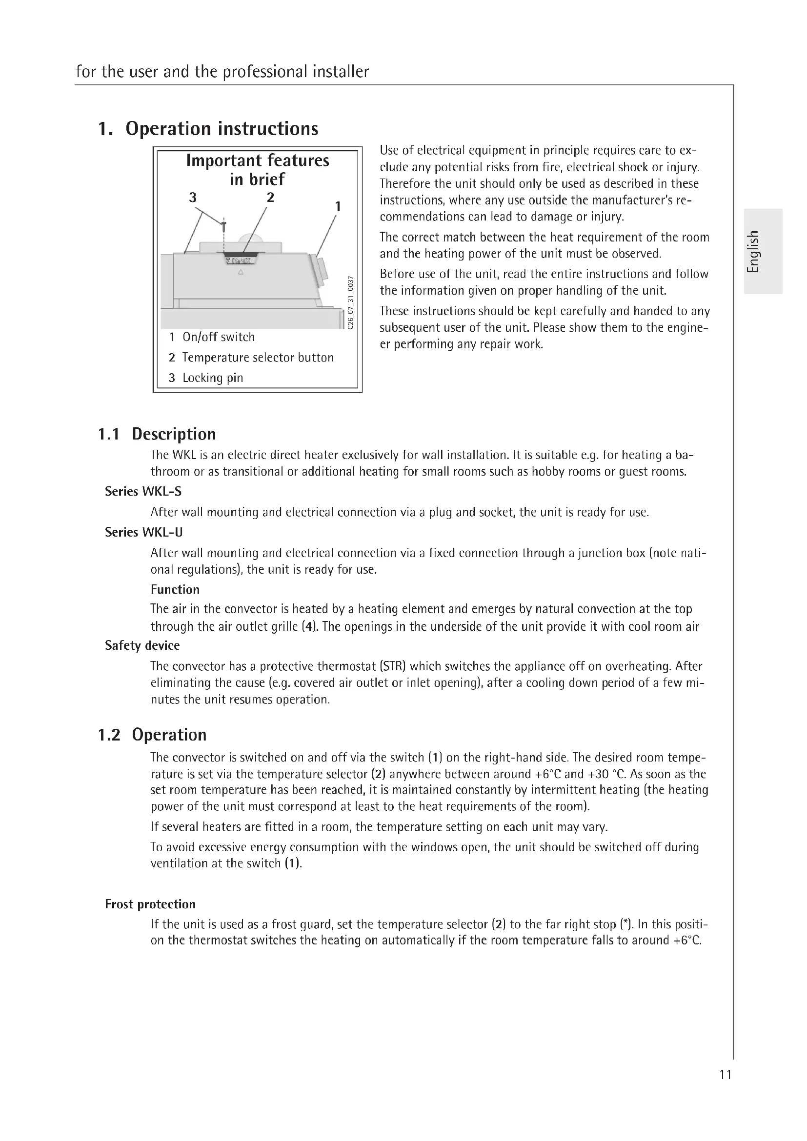
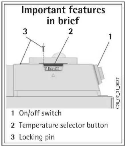
Important features in brief 1 On/off switch 2 Temperature selector button 3 Locking pin C26_07_31_0037Use of electrical equipment in principle requires care to exclude any potential risks from fire, electrical shock or injury. Therefore the unit should only be used as described in these instructions, where any use outside the manufacturer's recommendations can lead to damage or injury.
The correct match between the heat requirement of the room and the heating power of the unit must be observed.
Before use of the unit, read the entire instructions and follow the information given on proper handling of the unit.
These instructions should be kept carefully and handed to any subsequent user of the unit. Please show them to the engineer performing any repair work.
1.1 Description
The WKL is an electric direct heater exclusively for wall installation. It is suitable e.g. for heating a bathroom or as transitional or additional heating for small rooms such as hobby rooms or guest rooms.
Series WKL-S
After wall mounting and electrical connection via a plug and socket, the unit is ready for use.
Series WKL-U
After wall mounting and electrical connection via a fixed connection through a junction box (note national regulations), the unit is ready for use.
Function
The air in the convector is heated by a heating element and emerges by natural convection at the top through the air outlet grille (4). The openings in the underside of the unit provide it with cool room air
Safety device
The convector has a protective thermostat (STR) which switches the appliance off on overheating. After eliminating the cause (e.g. covered air outlet or inlet opening), after a cooling down period of a few minutes the unit resumes operation.
1.2 Operation
The convector is switched on and off via the switch (1) on the right-hand side. The desired room temperature is set via the temperature selector (2) anywhere between around +6°C and +30 °C. As soon as the set room temperature has been reached, it is maintained constantly by intermittent heating (the heating power of the unit must correspond at least to the heat requirements of the room).
If several heaters are fitted in a room, the temperature setting on each unit may vary.
To avoid excessive energy consumption with the windows open, the unit should be switched off during ventilation at the switch (1).
Frost protection
If the unit is used as a frost guard, set the temperature selector (2) to the far right stop (*). In this position the thermostat switches the heating on automatically if the room temperature falls to around +6°C.
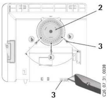
Limiting the thermostat
Using the two pins on the back of the switch housing (3), the thermostat can be fixed in a particular setting. To fix a desired temperature, push pin a into the hole opposite.
To limit the temperature adjustment range, set the minimum and maximum values on the selector knob and mark these by inserting pin b into the opposite, slightly offset hole each time.
text_image
2 b b a 3 3 C26 07.31_00381.2.1 External room thermostat
If necessary the unit can be operated with a commercial external room thermostat. The temperature selector (2) must be turned to the right stop (MAX). The room thermostat should be located as far as possible from the unit and at least 1.5 m high.
1.2.2 Shutting Down
To shut down the unit, move the switch to the OFF position and remove the mains plug from the wall socket (do not pull out the plug using the lead).
1.3 Safety notes

The unit should not be operated
- in rooms at risk of explosion or fire from chemicals, dust, gas or vapour,
- in the immediate vicinity of pipes or containers which transport or contain flammable or explosive substances,
- if the minimum distances from adjacent object surfaces are not observed.
● Installation (electrical installation), first operation and maintenance of this unit may only be performed by an accredited expert according to these instructions.
- The unit must not be operated if in the same room work is performed such as floor laying, grinding, sealing, cleaning with petrol and care (spray, beeswax) and similar.
● The housing surfaces of the unit and the emerging air are hot during operation (over 80 °C). Risk of burns!
Keep small children away from the unit.
- Do not place objects on the unit, lean objects against it or store anything between the heater and the wall (e.g. drying washing).
Also do not place in the immediate vicinity of the unit any flammable, combustible or heat-insulating objects or substances such as laundry, blankets, newspapers, containers of beeswax or petrol, spray cans or similar. Risk of explosion!

To prevent overheating of the unit, it must not be covered.
● A For objects of all types e.g. furniture, curtains, hangings or textiles or other flammable or non-flammable materials, the following minimum distances from the unit must be observed:
To the air outlet grille 500 mm
To the sides 100 mm
To the top 150 mm
To the underside 100 mm
To the back wall 26 mm
Hot air must be able to escape unobstructed.
● The unit may not be used as a freestanding unit.
- Do not stand on the unit.
- No changes may be made to the unit.
- The unit should never be left in operation accidentally.
- Special care is required if the unit is used in the presence of children, the infirm or animals. Risk of injury!
- If part of the unit is damaged, if the unit has fallen off or is malfunctioning, do not operate.
- In case the power mains supply is damaged, it must be replaced by the manufacturer, the customer service of the manufacturer or an authorized and qualified person. Mandatory for hazard prevention.
1.4 Care and maintenance
If the unit housing shows a slight brown discolouration it should be cleaned as soon as possible with a damp warm cloth:
When the appliance is cold it can be cleaned with normal cleaning agents.
Avoid scouring or aggressive cleaning agents.
Moisture must not penetrate the unit.
Do not spray cleaning spray into the air slots.
For regular maintenance we recommend checking the control and adjustment elements. At the latest 10 years after first use, the safety, control and adjustment elements should be checked by an expert.
What to do if ... ?
- the unit does not get hot?
Check that ... ... the ON/OFF switch is turned on. ... in your fuse box, the corresponding fuse is intact or whether the breaker has tripped. Eliminate cause! If the heater still does not warm up, call customer service!
• the unit switches itself off?
Check whether it is covered, so it could have overheated (e.g. covered air outlet or inlet opening). Eliminate cause! If it does not warm up again after a few minutes' cooling down period, call customer service!
- customer service is called?
Read the type (Typ) and number (Nr.) from the rating plate (8) on the unit and tell customer service!
AEG
Typ: WKL ....
2. Installation instructions
This unit may only be erected and electrically connected by a specialist following the installation instructions.
First remove the packaging and check accessories and any enclosures, ensure that no accessories remain in the packaging material.
2.1 Structure of unit
4 Air outlet grid
5 Wall bracket
6 Closing bolt
7 Mains connection cable
8 Rating plate
Technical data
| Type WKL 503 S | WKL 503 U | WKL 753 SWKL 753 U | WKL 1003 SWKL 1003 U | WKL 1503 SWKL 1503 U | WKL 2003 SWKL 2003 U | WKL 2503 SWKL 2503 U | WKL 3003 SWKL 3003 U | |
| Height mm 450 | ||||||||
| Width mm 370 445 | 445 | 590 740 890 | 1040 | |||||
| Depth with wall bracket | mm | 78100 | ||||||
| Dimension A mm | 121 | 195 195 343 49 | 1 639 787 | |||||
| Weight kg 4,0 4,6 | 4,6 6,0 | 7,2 8,4 9,9 | ||||||
| Connection 1/N ~ | 230 V | |||||||
| Power | kW | 0,5 | 0,75 | 1,0 | 1,5 | 2,0 | 2,5 | 3,0 |
| Temperature adjustment range | °C | approx. 6 to 30 | ||||||
| Frost protection | °C | approx. 6 | ||||||
| Protection class | II | |||||||
| Protection mode | IP 24, splash water protected | |||||||
| Approval | see unit rating palte | |||||||
2.2 Provisions and specification
The unit should not be operated
- in rooms at risk of explosion or fire from chemicals, dust, gas or vapour,
- in the immediate vicinity of pipes or containers which transport or contain flammable or explosive substances,
- if the minimum distances from adjacent object surfaces are not observed.
In workshops or other rooms in which exhaust gases, oil or petrol vapours etc. occur or where solvents and chemicals are used, persistent odour problems and where applicable contamination can occur.
● The unit may only be fitted to a vertical wall, temperature-resistant up to at least 80 °C.
● Minimum distances from adjacent object surfaces must be observed.
- All electrical connection and installation work must be performed to VDE regulations (0100), the regulations of a competent utility company and the corresponding national and regional regulations.
● The unit must not be mounted directly below a wall socket.
- If the unit is permanently connected to an AC network (junction box) an isolation distance of at least 3mm is required on all poles for isolation from the network. For this, circuit breakers, LS switches, fuses etc. can be used.
Installation with permanent connection cables is not permitted.
● The rating plate must be observed. The rated voltage must correspond to the nominal voltage.
- On installation of the heater in rooms with a bath and/or shower, the protection area to VDE 0100 part 701 as specified on the unit rating plate must be observed.
● The unit must be mounted such that the switch and control units are out of reach of a person in the bath or shower. - The mains connection cable may only be replaced with original spare parts by experts.
2.3 Installation
2.3.1 Installation of wall bracket B
The wall bracket should be used as a template for fixing the appliance to the wall. It also helps to keep the necessary ground clearance. To attach the unit proceed as follows:
- Place the wall bracket (5) holding the centre point horizontally on the ground and mark the holes a and d on the assembly wall;
- II Raise the wall bracket so that the holes b in the wall bracket coincide with the marks just made on the assembly wall;
● Mark holes c and d on the wall bracket on the assembly wall; - At all four markings drill holes and attach the wall bracket to the wall using suitable fixing materials (wall plugs and screws) dependig on the type of wall. The vertical slots allow adjustment for an offset in the fixing holes.
2.3.2 Unit installation C
The convector is mounted by attaching the slots on the rear simultaneously to the four tabs of the wall bracket pressing down to lock. The closing bolt (6) of the wall bracket is then turned clockwise to the stop, locking the fixing. To remove the convector, unscrew the locking bolt and lift the unit slightly, pulling it forwards and out of the bracket.
2.4 Electrical connection
The required electrical connection is AC 230V.
For fixed connection, an earth socket or junction box should be installed at a distance of at least 100 mm to the side of the heater.
2.5 Handover
Explain to the user how the unit functions. Draw his attention in particular to the safety instructions. Give the user these operating and usage instructions.
3. Guarantee
For guarantees please refer to the respective terms and conditions of supply for your country.

The installation, electrical connection and first operation of this appliance should be carried out by a qualified installer.
The company does not accept liability for failure of any goods supplied which accor-dance with the manufacturer's instructions.
3.1 Environment and recycling
Recycling of obsolete appliances

Appliances with this label must not be disposed off with the general waste. They must be collected separately and disposed off according to local regulations.
AEG Home Comfort Czech
K Hájům 946
Tel. 0 73 - 6 23 00 00
Fax 0 73 - 6 23 11 41
Österreich
Stiebel Eltron Ges. m.b.H.
Eferdinger Str. 73
4600 Wels
Tel. 0 72 42 - 4 73 67 - 0
Fax 0 72 42 - 4 73 67 - 42
Polska
Stiebel Eltron Polska Sp. z o.o.
ul. Instalatorów 9
02-237 Warszawa
Tel. 0 22 - 8 46 48 20
Fax 0 22 - 8 46 67 03
Schweiz
EHT Haustechnik AG
Industriestrasse 10
5506 Mägenwill
Tel. 0 62 - 8 89 92 14
Fax 0 62 - 8 89 91 26