PerfectView CAM604 - Dashcam WAECO - Free user manual and instructions
Find the device manual for free PerfectView CAM604 WAECO in PDF.

| Product type | Reversing camera and traffic observation camera (Dashcam) |
| Brand | Waeco |
| Model | PerfectView CAM604 |
| Dimensions (L x H x D) | 83 x 70 x 57 mm (with bracket) |
| Weight | Approx. 300 g |
| Power supply | 10 - 16 V DC, max. consumption 6 W |
| Sensor | 1/4" color CMOS sensor, approx. 5,000,000 pixels (2592 x 1944) |
| TV system | PAL |
| Sensitivity | < 1 Lux (without LED), 0 Lux (with infrared LED) |
| Viewing angle – Far vision | 63° horizontal, 52° vertical, 83° diagonal |
| Viewing angle – Near vision | 140° horizontal, 94° vertical, 153° diagonal |
| Microphone sensitivity | Approx. 42 dB |
| Storage temperature | -40 °C to +80 °C |
| Operating temperature | -30 °C to +70 °C |
| Housing material | Aluminum |
| Protection rating | Waterproof (do not use high-pressure cleaner) |
| Main functions | Switching between far and near vision, panoramic mode, mirror display, infrared LED for night vision, built-in microphone |
| Package contents | Camera, bracket, adapter box, mounting hardware, manual |
| Maintenance and cleaning | Clean with a damp cloth; do not use sharp, hard objects or detergents |
| Safety | Install at least 2 m high; secure firmly to prevent detachment |
| Repairability | Do not open the camera; contact the manufacturer or an authorized dealer for any repairs |
Frequently Asked Questions - PerfectView CAM604 WAECO
User questions about PerfectView CAM604 WAECO
0 question about this device. Answer the ones you know or ask your own.
Ask a new question about this device
Download the instructions for your Dashcam in PDF format for free! Find your manual PerfectView CAM604 - WAECO and take your electronic device back in hand. On this page are published all the documents necessary for the use of your device. PerfectView CAM604 by WAECO.
USER MANUAL PerfectView CAM604 WAECO
natural_image
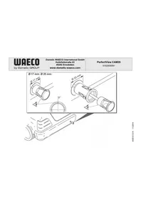
Technical line drawing of three mechanical components: a cylindrical housing, a rectangular enclosure with circular cutouts, and a multi-pin connector (no text or symbols present)PerfectView CAM604
DE 10 Heavy Duty Farbkamera
Montage- und Bedienungsanleitung
EN 26 Heavy-duty colour camera
Installation and Operating Manual
FR 41 Caméra couleur Heavy Duty
Instructions de montage et de service
ES 57 Cámara a color Heavy Duty
Instrucciones de montaje y de uso
IT 73 Telecamera a colori Heavy Duty
Istruzioni di montaggio e d'uso
NL 89 Heavy duty kleurencamera
Montagehandleiding en gebruiks-
aanwijzing
DA 105 Heavy duty-farvekamera
Monterings- og betjeningsvejledning
SV 120 Heavy Duty-färgkamera
Monterings- och bruksanvisning
NO 135 Heavy Duty fargekamera
Monterings- og bruksanvisning
FI 150 Heavy-duty-värikamera
Asennus- ja käyttöohje
PT 165 Câmara a cores Heavy Duty
Instruções de montagem e manual de instruções
RU 181 Цветная камера Heavy Duty
Инструкция по монтажу и
эксплуатации
PL 198 Kamera kolorowa Heavy Duty
Instrukcja montażu i obsługi
CS 214 Barevná kamera Heavy Duty
Návod k montáži a obsluze
SK 229 Vysokovýkonná farebná kamera
Návod na montáž a uvedenie do prevádzky
HU 244 Heavy Duty színes kamera
Szerelési és használati útmutató
DE Fordern Sie weitere Informationen zur umfangreichen Produktpalette aus dem Hause Dometic WAECO an. Bestellen Sie einfach unsere Kataloge kostenlos und unverbindlich unter der Internetadresse: www.dometic-waeco.de
EN We will be happy to provide you with further information about Dometic WAECO products. Please order our free catalogue with no obligation to buy on our homepage: www.dometic-waeco.com
FR Demandez d'autres informations relatives à la large gamme de produits de la maison Dometic WAECO. Commandez tout simplement notre catalogue gratuitement et sans engagement à l'adresse internet suivante : www.dometic-waeco.com
ES Solicite más información sobre la amplia gama de productos de la empresa Dometic WAECO. Solicite simplemente nuestros catálogos de forma gratuita y sin compromiso en la dirección de Internet: www.dometic-waeco.com
IT Per ottenere maggiori informazioni sull'ampia gamma di prodotti Dometic WAECO è possibile ordinare una copia gratuita e non vincolante del nostro Catalogo all'indirizzo Internet: www.dometic-waeco.com
NL Maak kennis met het omvangrijke productscala van de firma Dometic WAECO. Bestel onze catalogus gratis en vrijblijvend onder het internetadres: www.dometic-waeco.com
DA Bestil yderligere information om det omfattende produktudvalg fra Dometic WAECO. Bestil vores katalog gratis og uforpligtende på internetadressen: www.dometic-waeco.com
SV Inhämta mer information om den omfattande produktpaletten från Dometic WAECO: Beställ våra kataloger gratis och utan förpliktelser under vår Internetadress: www.dometic-waeco.com
NO Be om mer informasjon om det rikholdige produktutvalget fra Dometic WAECO. Bestill vår katalog gratis uforbindtlig på Internettadressen: www.dometic-waeco.com
FI Pyytäkää lisää tietoja Dometic WAECOn kattavista tuotevalikoimista. Tilatkaa tuotekuvastomme maksutta ja sitoumuksetta internet-osoitteesta: www.dometic-waeco.com
PT Peça mais informação sobre a ampla gama de produtos da empresa Dometic WAECO. Peça simplesmente os nossos catálogos de forma gratuita e sem qualquer compromisso, disponível no site: www.dometic-waeco.com
RU Запросите дальнейшую информацию об обширном ассортименте продукции компании Dometic WAECO. Просто закажите наши каталоги на сайте www.dometic-waeco.com; эта услуга предоставляется бесплатно и ни к чему не обязывает.
PL Proszę się zapoznać z informacjami na temat szerokiej gamy produktów Dometic WAECO. Proszę zamówić nasz bezpłatny katalog i zapoznać się z niewiążącą ofertą pod adresem: www.dometic-waeco.com
CS Žádejte další informace o rozsáhlé nabídce výrobků firmy Dometic WAECO. Stačí zdarma a nezávazně objednat naše katalogy na internetové adrese: www.dometic-waeco.com
SK Vyžiadajte si d'alšie informácie o rozsiahlej palete výrobkov Dometic WAECO. Objednajte si bezplatne a nezáväzne náš katalóg na internetovej adrese: www.dometic-waeco.com
Kérjen további információkat a Dometic WAECO cég széles körü termékpalettájáról. Rendelje meg ingyenes katalógusainkat kötelezettség nélkül a következő internetcímen: www.dometic-waeco.de
natural_image
Technical diagram showing a welding process with two intersecting lines and arrows indicating motion (no text or symbols)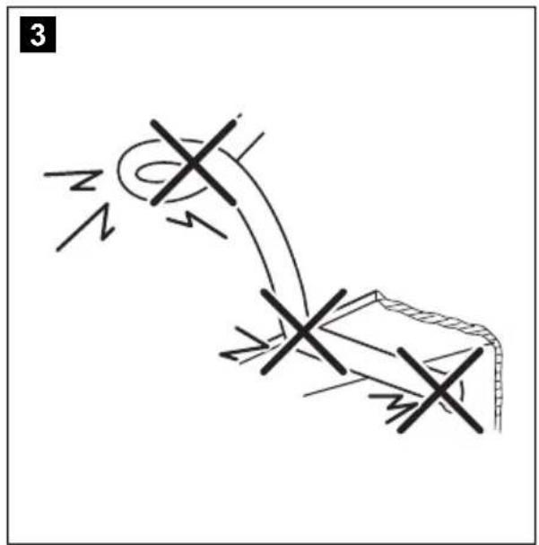
natural_image
Illustration of a hand holding a device with a diagonal line intersecting it, no text or symbols present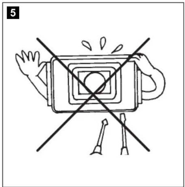
natural_image
Diagram of a device with a central square and two crossed lines, no text or symbols present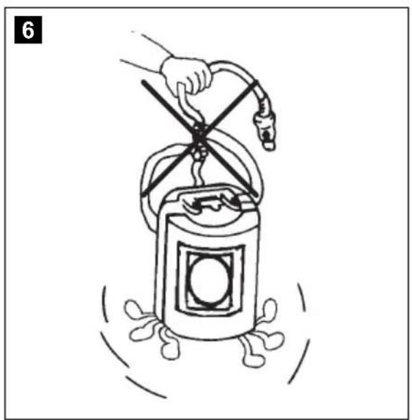
natural_image
Illustration of a hand using a tool to lift a cylindrical container with a handle, surrounded by motion lines (no text or symbols)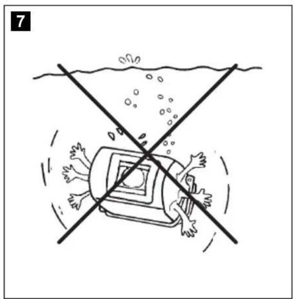
natural_image
Illustration of a submerged object with people reacting in shock, crossing a horizontal line above water (no text or symbols)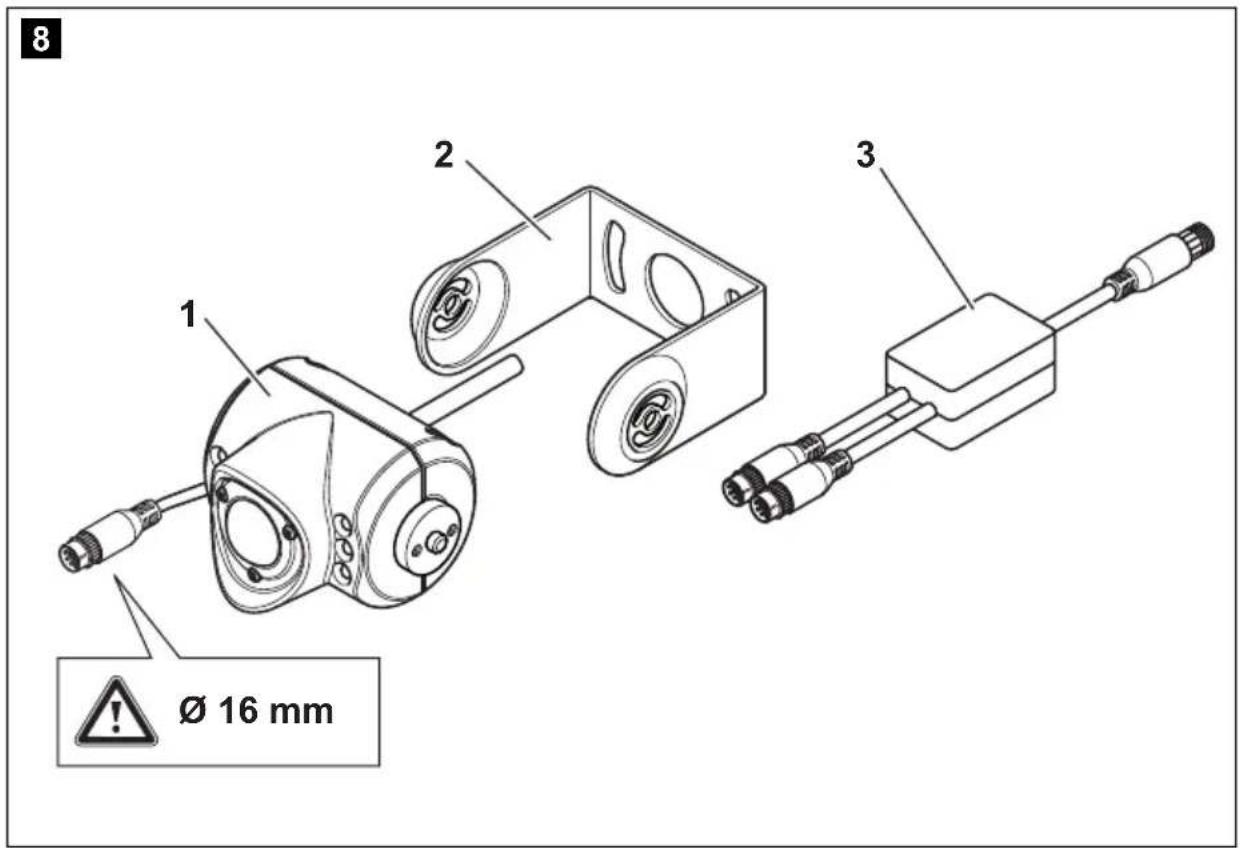
11
natural_image
Line drawing of two hands holding a small object, no text or symbols present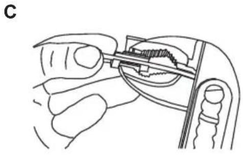
natural_image
Line drawing of a hand holding a small mechanical component, possibly a tool or device, with no visible text or symbols.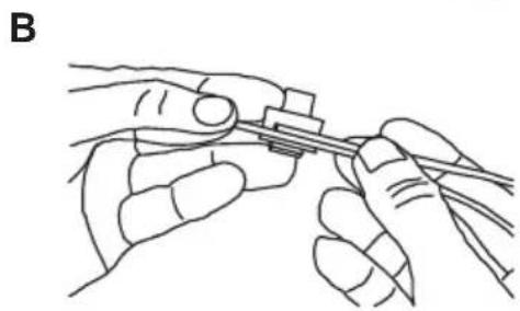
natural_image
Line drawing of two hands holding a tool, no text or symbols present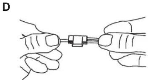
natural_image
Illustration of two hands holding a small mechanical component connected by a string (no text or symbols)12
natural_image
Diagram of a coiled tube or pipe with internal parallel grooves (no text or symbols)13
natural_image
Line drawing of a mechanical device with two wheels and a curved handle, no text or symbols present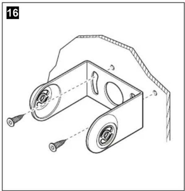
natural_image
Technical line drawing of a mechanical bracket with two circular components and screw fasteners, no text or symbols present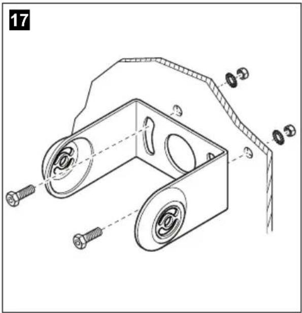
natural_image
Technical line drawing of a mechanical device with a circular component and a curved handle (no text or symbols)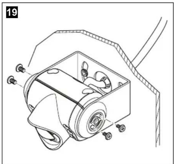
natural_image
Technical line drawing of a mechanical device with gears and mounting holes (no text or symbols)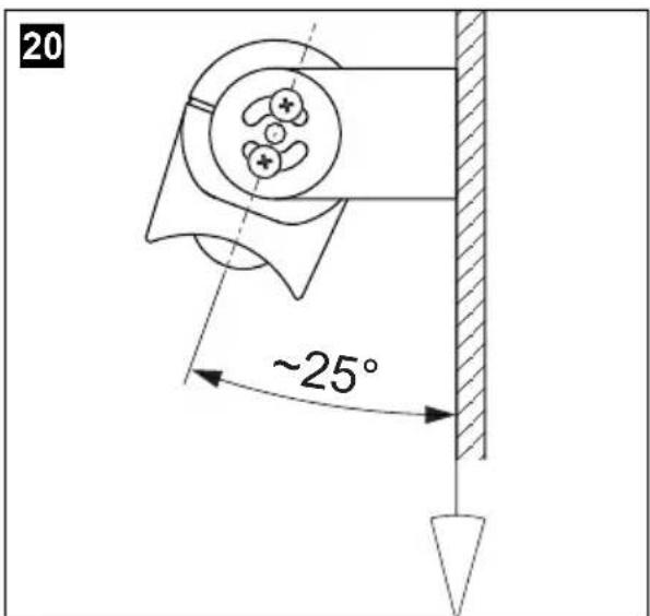
21
A
natural_image
Simple line drawing of a rectangular frame with a vertical dashed line and two side slots at the bottom (no text or symbols)B
natural_image
Mechanical diagram showing a rotating wheel and gear mechanism with motion arrows (no text or labels)22
Please read this instruction manual carefully before installation and first use, and store it in a safe place. If you pass on the product to another person, hand over this instruction manual along with it.
Table of contents
1 Explanation of symbols 27
2 Safety and installation instructions.... 27
3 Scope of delivery 30
4 Accessories 30
5 Intended use 30
6 Technical description 31
7 Notes on the electrical connection ..... 31
8 Fitting the camera 34
9 Cleaning and caring for the camera....39
10 Warranty 39
11 Disposal 39
12 Technical data .... 40
1 Explanation of symbols

WARNING!
Safety instruction: Failure to observe this instruction can cause fatal or serious injury.

CAUTION!
Safety instruction: Failure to observe this instruction can lead to injury.

NOTICE!
Failure to observe this instruction can cause material damage and impair the function of the product.

NOTE
Supplementary information for operating the product.
▶ Action: This symbol indicates that action is required on your part. The required action is described step-by-step.
√This symbol describes the result of an action.
Fig. 1 5, page 3: This refers to an element in an illustration. In this case, item 5 in figure 1 on page 3.
2 Safety and installation instructions
Please observe the safety instructions and stipulations issued by the vehicle manufacturer and service workshops.
The manufacturer accepts no liability for damage in the following cases:
● Faulty assembly or connection
● Damage to the product resulting from mechanical influences and excess voltage
- Alterations to the product without express permission from the manufacturer
● Use for purposes other than those described in the operating manual
Therefore, please observe the following instructions:
- To prevent the risk of short circuits, always disconnect the negative terminal of the vehicle's electrical system before working on it.
If the vehicle has an additional battery, its negative terminal should also be disconnected.
- Inadequate supply cable connections could result in short circuits, causing:
- Cable fires
– The airbag being triggered
– Damage to electronic control equipment
– Electrical malfunctions (indicators, brake light, horn, ignition, lights)
- When working on the following cables, only use insulated cable terminals, plugs and flat sockets:
- 30 (direct supply from positive battery terminal)
- 15 (connected positive terminal, behind the battery)
- 31 (return cable from the battery, earth)
- 58 (reversing light)
Do not use porcelain wire connectors.
- Use a crimping tool (fig. 1 10, page 3) to connect the cables.
- Screw the cable when connecting cable 31 (earth)
- Screw on the cable using a cable terminal and serrated washer to one of the vehicle's earth bolts or
- Screw the cable to the bodywork using a cable terminal and a self-tapping screw
Make sure there is a good earth connection.
If you disconnect the negative terminal of the battery, all data stored in the volatile memories will be lost.
- The following data must be reset, depending on the vehicle equipment options:
- Radio code
- Vehicle clock
- Timer
- On-board computer
- Seat position
You can find instructions for making these settings in the operating manual.
Observe the following installation instructions:
- Secure the parts of the camera installed in the vehicle in such a way that they cannot become loose under any circumstances (sudden braking, accidents) and cause injuries to the occupants of the vehicle.
- Secure any parts of the system concealed by the bodywork in such a manner that they cannot be come loose or damage other parts or cables, or impair vehicle functions (steering, pedals, etc).
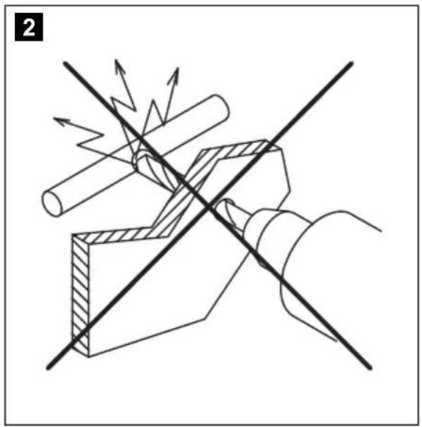
- To prevent damage when drilling, make sure there is sufficient space on the other side for the drill head to come out (fig. 2, page 4).
- Deburr all drill holes and treat them with a rust-protection agent.
● Always follow the safety instructions of the vehicle manufacturer. Some work (e.g. on retention systems such as the AIRBAG etc.) may only be performed by qualified specialists.
Observe the following instructions when working with electrical parts:
- When testing the voltage in electrical cables, only use a diode test lamp (fig. 1 8, page 3) or a voltmeter (fig. 1 9, page 3).
Test lamps with a bulb (fig. 1 12, page 3) consume voltages which are too high and can damage the vehicle's electronic system.
- When making electrical connections, ensure that:
– they are not kinked or twisted
– they do not rub on edges
- they are not laid in sharp-edged ducts without protection (fig. 3, page 4).
● Insulate all connections.
- Secure the cables against mechanical wear by using cable binders or insulating tape, for example on existing cables.
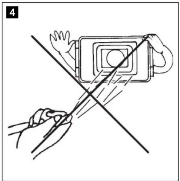
The camera is watertight. However, the seals on the camera cannot withstand a high-pressure cleaner (fig. 4, page 4). Therefore, you should observe the following instructions when handling the camera:
- Do not open the camera, as this impairs the leak tightness and the function of the camera (fig. 5, page 4).
- Do not pull at the cables, as this impairs the tightness and the function of the camera (fig. 6, page 4).
● The camera is not suitable for use under water (fig. 7, page 4)!
3 Scope of delivery
| No. fig. 8, quantity Designation Item no. page 5 |
| 1 1 Camera 9102000071 |
| 2 1 Camera bracket |
| 3 1 Adapter box 9102200154 |
| - 1 Fastening material |
| - 1 Installation and operating manual |
4 Accessories
Available as accessories (not included in the scope of delivery):
Designation Item no.
Connection cable 9102200030
5 Intended use
The heavy-duty CAM604 colour camera with traffic surveillance feature (item no. 9102000071) is intended primarily for use in vehicles. It can be used in reversing video systems to observe the space around the vehicle from the driver's seat when manoeuvring or parking, for example.

WARNING!
Reversing video systems are designed merely as an additional aid for reversing, however this does not relieve you of the duty to take proper care when reversing.
6 Technical description
The colour camera with integrated microphone is encased in an aluminium housing and transmits image and sound to a monitor via a cable. The infrared LEDs improve night vision.
The camera can switch between long-distance and close area. The long-distance mode shows the space behind the vehicle as if you were looking through a rear window. The close area mode switches on when you engage the reverse gear and shows the space directly behind the vehicle.

NOTE
The cameras is equipped with a reverse display at the factory. Any monitor that is connected therefore needs a normal picture function.
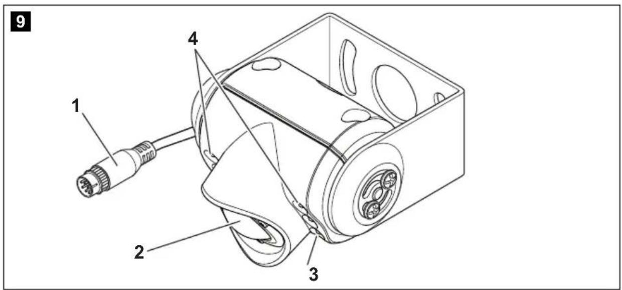
The camera consists of the following elements:
| No. in fig. 9, page 5 Designation |
| 1 6-pin connection cable |
| 2 Lens |
| 3 Microphone |
| 4 Infrared LEDs |
7 Notes on the electrical connection
7.1 Laying cables

NOTICE! Beware of damage
- When drilling holes, check beforehand that there is sufficient space on the other side for the drill head to come out.
- Cables and connections that are not properly installed will cause malfunctions or damage to components. Correct installation of cables and connections ensures lasting and trouble-free operation of the retrofitted components.
- The cables may not be exposed for long periods to solvents such as benzene, since solvents can damage the cable.
Therefore, please observe the following instructions:
- As far as possible, use original ducts for laying the cables, or other suitable options such as panelling edges, ventilation grilles or dummy plugs. If no openings are available, you must drill holes for the cables. Check beforehand that there is sufficient space on the other side for the drill head to emerge.
- Wherever possible, lay cables inside the vehicle, as they are better protected there than outside. If you do need to lay a cable outside the vehicle, ensure that it is well fastened (use additional cable ties, insulating tape etc.).
- To prevent damage to the cables when laying them, ensure that they are far enough away from hot or moving vehicle components (exhaust pipes, drive shafts, light systems, fans, heaters, etc.). Use corrugated piping or other protective materials to protect against mechanical wear.
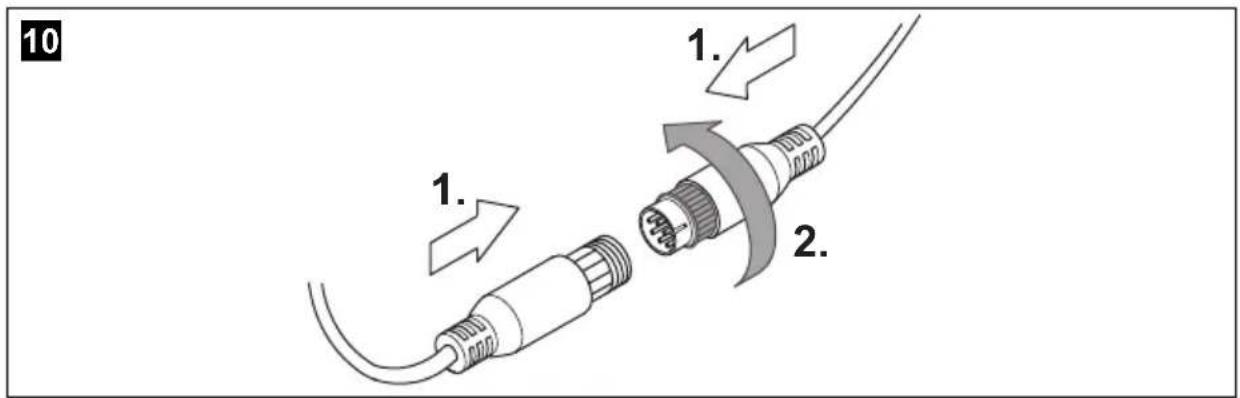
- Screw on the plug connections for the connecting cables to protect them against water penetration (fig. 10, page 5).
- When laying the cables, make sure:
– they are not kinked or twisted
– they do not rub on edges
- they are not laid in sharp-edged ducts without protection (fig. 3, page 4).
- Attach the cables securely in the vehicles to prevent tripping hazards. This can be performed by using cable binders, insulating tape or gluing in place with adhesives.
- Protect every through-hole made in the bodywork against water penetration, e.g. by using a cable with a sealant and by spraying the cable and the cable sleeve with sealant.

NOTE
Only start sealing through-holes when you have completed all installation work on the camera and have laid the required cable lengths.
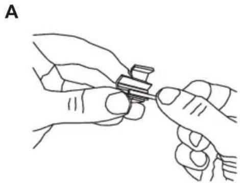
7.2 Using branch connectors
To prevent loose connections in the branch connectors, it is important to ensure that the cable cross sections fit into the branch connectors.
To use the branch connectors, proceed as follows:
▶Insert the cable to be tapped in the front groove of the branch connector (fig. 11 A, page 6)
▶Insert the end of the new cable up to approx. 3/4 of the way into the rear groove (fig. 11 B, page 6)
▶ Use a pair of combination pliers to close the connector by pressing the metal pin in. This creates an electrical connection (fig. 11 C, page 6).
▶Press down the safety cap until it snaps into place.
▶ Check that the connection is secure by gently tugging the cable (fig. 11 D, page 6).
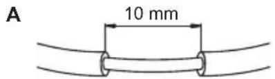
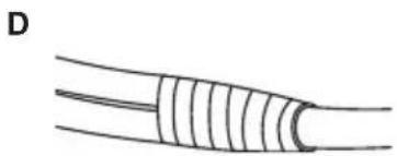
7.3 Creating clean soldering joints
Proceed as follows to solder a cable to the original cables:
▶ Strip approx 10 mm of insulation from the end of the original cable (fig. 12 .A, page 6).
▶ Strip approx 15 mm of insulation from the end of the cable to be connected (fig. 12.B, page 6).
▶Wind the cable to be connected around the original cable and solder the two cables together (fig. 12 C, page 6).
▶ Insulate the two cables with insulating tape (fig. 12 D, page 6).
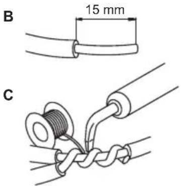
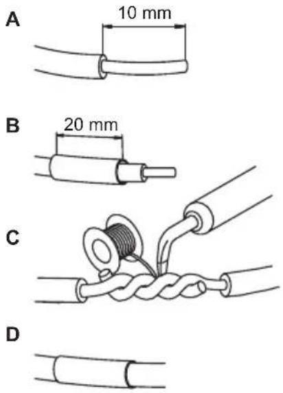
Proceed as follows to solder two cables together:
▶ Strip the two cables (fig. 13 A, page 6).
▶ Place a shrink sleeve with a length of approx. 20 mm over the cable (fig. 13 B, page 6).
▶ Twist the cables together and solder them (fig. 13 C, page 6).
▶ Place a shrink sleeve over the soldered point and heat it briefly (fig. 13 D, page 6)
8 Fitting the camera
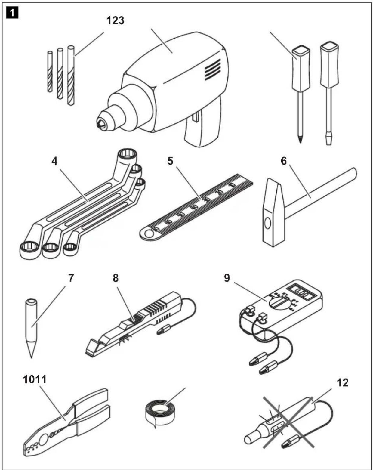
8.1 Tools required
For installation and assembly, you will need the following tools:
- Drill bit set (fig. 1 1, page 3)
● Electric drill (fig. 1 2, page 3) - Screwdriver (fig. 1 3, page 3)
- Set of ring or open-ended spanners (fig. 1 4, page 3)
● Measuring ruler (fig. 1 5, page 3)
● Hammer (fig. 1 6, page 3)
● Centre punch (fig. 1 7, page 3)
To establish and test the electrical connection, the following tools are required:
- Diode test lamp (fig. 1 8, page 3) or voltmeter (fig. 1 9, page 3)
● Crimping tool (fig. 1 10, page 3)
● Insulating tape (fig. 1 11, page 3)
● Cable bushing sleeves (optional)
To fasten the cables you may require additional cable binders.
8.2 Fitting the camera

CAUTION!
Select a location for the camera and attach it firmly enough so that it cannot under any circumstances fall off and injure bystanders (e.g. by being knocked off by branches brushing over the roof of the vehicle).

NOTE
If installing the camera alters the vehicle height or the length specified in the vehicle documents, your vehicle must be inspected by the appropriate authorities.
This authority must note any such changes your vehicle documents.
Observe the following installation instructions:
- To provide a suitable viewing angle, the camera must be attached at a height of at least 2 m.
Ensure that you have a firm place from which to work when mounting the camera. - Make sure that the installation location of the camera is sufficiently firm (e.g. to prevent the camera from being knocked down by branches that may brush the roof of the vehicle).
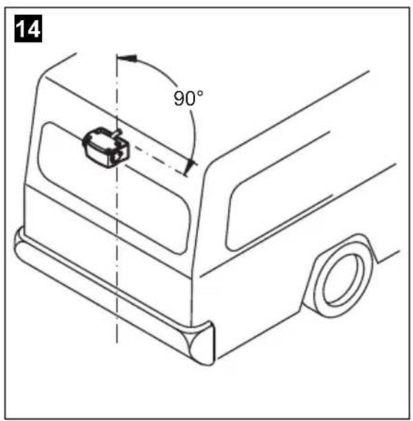
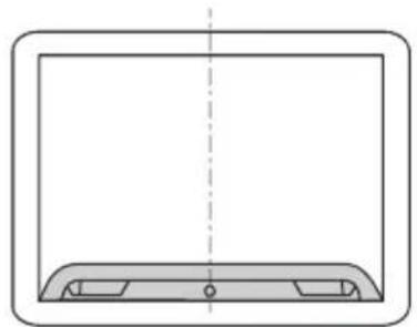
- Mount the camera horizontally and in the middle of the rear of the vehicle (fig. 14, page 7).
- The most secure type of attachment is with screws fitted through the body. Please observe the following instructions:
- There must be sufficient space behind the chosen installation location to be able to carry out the mounting procedure.
- Suitable measures must be taken to prevent water penetrating through any holes made (e.g. by using screws and sealant and/or spraying the outer attachment parts with sealant).
- The location on the body where you wish to attach the camera must be rigid enough to allow the camera to be tightly fastened.
- Check beforehand that there is sufficient space on the other side for the drill head to come out (fig. 2, page 4).
- If you are not sure about the location you have chosen, ask your vehicle manufacturer or dealer.

NOTE
We recommend greasing the threads of the bolts to prevent corrosion.
To perform the installation, proceed as follows:
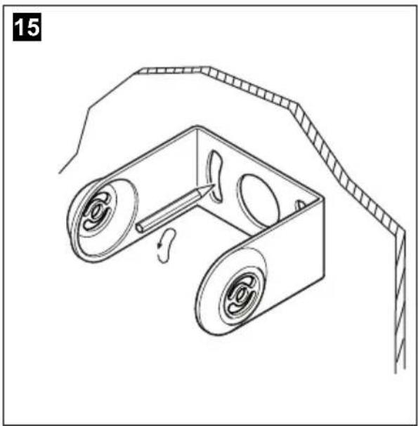
▶Hold the camera holder at the chosen location and mark at least two different points for the drill holes (fig. 15, page 7).
▶ Using a hammer and centre punch, gently pre-punch the previously marked points to prevent the drill head from slipping off.
If you want to screw on the camera with self-tapping screws (fig. 16, page 7):

NOTICE!
Self-tapping screws may only be fastened to steel metal with a minimum thickness of 1.5 mm.
▶ Drill the holes, with a ∅ of 6 mm, at each of the markings.
▶ Deburr all drill holes and apply rust-protection.
▶ Screw on the camera bracket using 6 x 20 mm self-tapping screws.
If you would like to attach the camera with threaded screws fitted through the construction (fig. 17, page 7):

NOTICE!
Ensure that nuts cannot be pulled through the body shell when they are tightened.
Use larger washers or metal plates if necessary.
▶ Drill the holes, with a ∅ of 6.5 mm, at each of the markings.
▶ Deburr all drill holes and apply rust-protection.
▶ Screw on the camera bracket using M6 x 20 self-tapping screws. Depending on the thickness of the construction, you may require longer threaded screws.
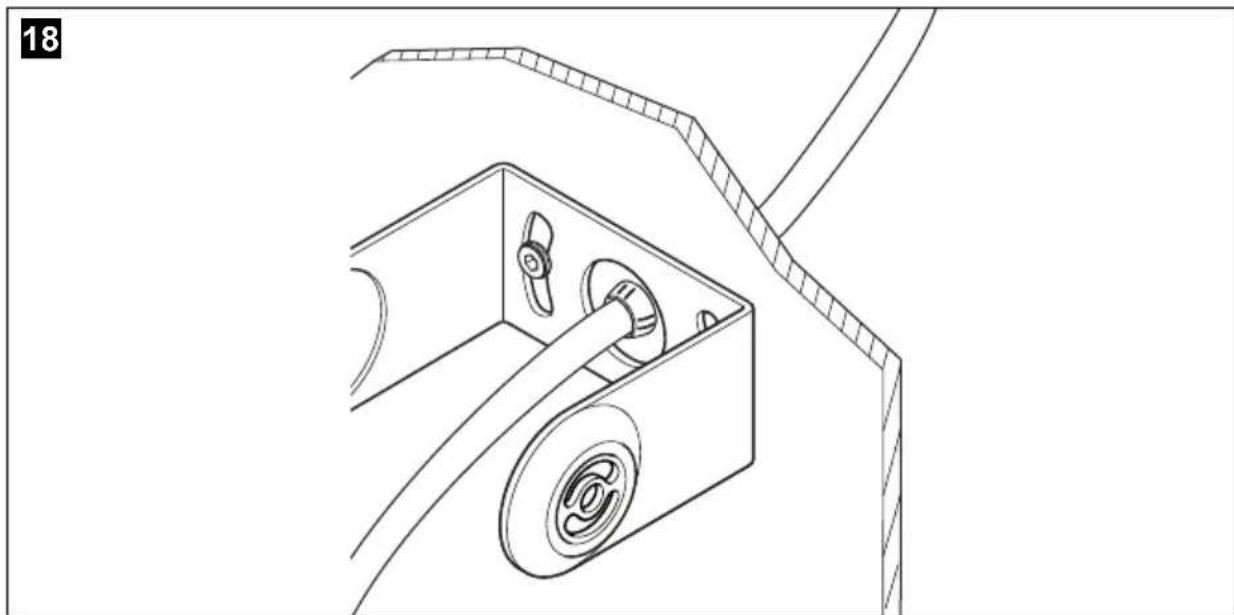
Creating a through-hole for the camera connection cable (fig. 18, page 8)

NOTE
If possible, use available openings, such as ventilation grilles, to feed the connection cables through. If there are no existing ducts, you must drill a hole of ∅ 16 mm.

NOTICE! Beware of damage
Check beforehand that there is sufficient space on the other side for the drill head to come out.
▶ Drill a hole of ∅ 16 mm near the camera.
▶ Deburr all drill holes that have been made in the sheet metal and apply rust-protection.
▶Place a cable sleeve in all sharp edged ducts.
Fastening the camera
▶ Push the camera into the bracket (fig. 19, page 8).

NOTICE!
Only use the screws supplied to mount the camera in the camera holder. Longer screws will damage the camera.
▶ Secure the camera loosely with the four M4 x 6 screws in the two other fixing holes (fig. 19, page 8).
The camera is now centred.
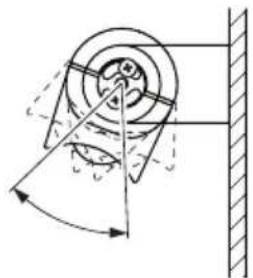
▶ Align the camera so that the lens is at an angle of approx. 25^ ± 5^ to the vertical axis of the vehicle (fig. 21, page 9).

NOTE
Do not tighten the four M4 x 6 screws until you have aligned the camera (see chapter “Checking the function and setting the camera” on page 38).
To do this you must first install and connect a monitor.
8.3 Connecting the camera

NOTE
- Lay the camera cable so that, should you need to remove the camera, you can access the plug connection between the camera and the extension cable easily. This facilitates the disassembly considerably.
- To minimise corrosion in the plug, apply a small amount of grease, such as pin grease, in one of the plugs.
▶Guide the camera cable into the vehicle interior.
▶Insert the plug of the camera cable into the socket of the extension cable (not included in scope of delivery, fig. 22 1, page 9).
▶Screw on the plug connection of the connecting cables to protect against water penetration (fig. 10, page 5).
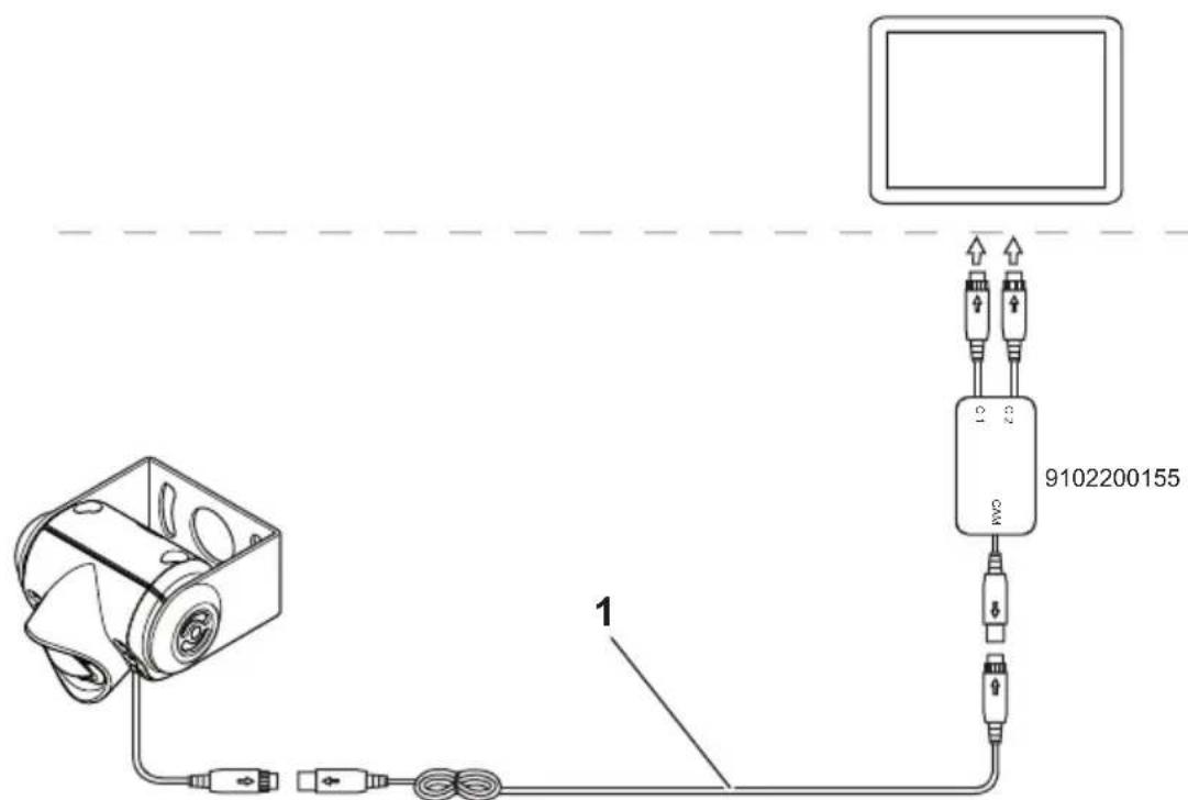
8.4 Connecting the connection box (fig. 22, page 9)
The control box is supplied ready for installation.
▶Fasten the control box at a suitable point.

NOTE
Connect the camera input for close-up (reversing camera) with the "C1" connection and the camera input for the long-distance with the "C2" connection.
▶Connect the control box electrically as follows:
- Connect the camera inputs on the monitor to the "C1" and "C2" connections.
- Connect the system cable from the camera to the "CAM" connection.
The camera is switched on and off in reverse gear or using the camera selection button on the monitor.
8.5 Checking the function and setting the camera
▶ Check the function of the camera after you have connected it to a monitor.
You can switch between the close-up and long-distance range of the camera by switching between the camera inputs on the display device.
▶Align the camera using the image on the monitor to help you:
The monitor image of the close-up should show the rear or the bumper of the vehicle at the bottom edge of the screen. The middle of the bumper should be in the middle of the screen (fig. 21, page 9).
▶Tighten the two fastening screws of the camera.
Settings for contrast and brightness can be made on the monitor.
9 Cleaning and caring for the camera

NOTICE!
Do not use sharp or hard objects or cleaning agents for cleaning as these may damage the product.
▶Occasionally clean the product with a damp cloth.
10 Warranty
The statutory warranty period applies. If the product is defective, please contact the manufacturer's branch in your country (see the back of the instruction manual for the addresses) or your retailer.
For repair and guarantee processing, please include the following documents when you send in the device:
● A copy of the receipt with purchasing date
● A reason for the claim or description of the fault
11 Disposal
▶Place the packaging material in the appropriate recycling waste bins wherever possible.
If you wish to finally dispose of the product, ask your local recycling centre or specialist dealer for details about how to do this in accordance with the applicable disposal regulations.
12 Technical data
| PerfectView CAM604 | |
| Item no.: 9102000071 | |
| Image sensor: 1/4" Color CMOS Sensor approx. 5000000 Pixel, 2592(H) x 1944(V) | |
| TV system: PAL | |
| Sensitivity: < 1 lux or | 0 lux with LED |
| Viewing angle: Close-up: 63° H, 52° V, 83° DLong-distance: 140° H, 94° V, 153° D | |
| Microphone sensitivity: Approx. 42 dB | |
| Storage temperature: -40 °C to +80 °C | |
| Operating temperature: -30 °C | bis +70 °C |
| Operating voltage: 10–16 V--- | |
| Consumption: | max. 6 W |
| Dimensions W x H x D (with bracket): | 83 x 70 x 57 mm |
| Weight: | Approx. 300 g |
| Certifications: |  |
6 Description technique
▶Skru fast kameraets to festeskruer.
Dometic Australia Pty. Ltd.
1 John Duncan Court
Varsity Lakes QLD 4227
+61 7 55076000
+61 7 55076001
Mail: sales@dometic-waeco.com.au
AUSTRIA
Dometic Austria GmbH
Commercial : info@dometic.fr
SAV/Technique : service@dometic.fr
HONG KONG
WAECO Impex Ltd.
Suites 2207-2211 · 22/F · Tower 1
The Gateway · 25 Canton Road,
Tsim Sha Tsui · Kowloon
Hong Kong
+852 24611386
吕 +852 24665553
Mail: info@dometic-waeco.com.hk
HUNGARY
Dometic Plc. Sales Office
Kerékgyártó u. 5.
H-1147 Budapest
+36 1 468 4400
+36 1 468 4401
Dometic Italy S.r.l.
Via Virgilio, 3
I-47100 Forli
+39 0543 754901
+39 0543 756631
Mail: info@dometic.it
NORWAY
Dometic Norway AS
Skolmar 24
N-3232 Sandefjord
+47 33428450
吕 +47 33428459
Mail: firmapost@waeco.no
POLAND
Dometic Poland Sp. z o.o.
Ul. Puławska 435A
02-801 Warszawa
Poland
+48 22 414 32 00
+48 22 414 32 01
Mail: info@dometic.pl
RUSSIA
Dometic RUS LLC
Komsomolskaya square 6-1
107140 Moscow
Russia
+7 495 780 79 39
+7 495 916 56 53
Mail: info@dometic.ru
SLOVAKIA
Dometic Slovakia s.r.o.
Tehelná 8
SK-98601 Fil'akovo
+421 47 4319 107
+421 47 4319 166
Mail: info@dometic.sk
SPAIN
Dometic Spain S.L.
Avda. Sierra del Guadarrama, 16
E-28691 Villanueva de la Cañada
Madrid
+34 902 111 042
+34 900 100 245
Mail: info@dometic.es
SWEDEN
Dometic Scandinavia AB
Gustaf Melins gata 7
Dometic Switzerland AG
Riedackerstrasse 7a
CH-8153 Rümlang (Zürich)
+41 44 8187171
+41 44 8187191
Mail: info@dometic-waeco.ch
TAIWAN
WAECO Impex Ltd.
Taipei Office
2 FL-3 · No. 56 Tunhua South Rd, Sec 2
Taipei 106, Taiwan
+886 2 27014090
昌 +886 2 27060119
Mail: marketing@dometic-waeco.com.tw
UNITED KINGDOM
Dometic UK Ltd.
Dometic House · The Brewery
Blandford St. Mary
Dorset DT11 9LS
+44 844 626 0133
昌 +44 844 626 0143
Mail: sales@dometic.co.uk
UNITED ARAB STATES
Dometic Middle East FZCO
P. O. Box 17860
S-D 6, Jebel Ali Freezone
Dubai, United Arab Emirates
+971 4 883 3858
+971 4 883 3868
Mail: info@dometic.ae
UNITED STATES OF AMERICA
Dometic Marine Division
2000 N. Andrews Ave. Extension
Pompano Beach, FL 33069 USA
+1 954 973 2477
+1 954 979 4414
Mail: marinesales@dometicusa.com