PerfectView CAM60ADR - Dashcam WAECO - Free user manual and instructions
Find the device manual for free PerfectView CAM60ADR WAECO in PDF.

| Product type | Vehicle backup camera (ADR compliant for dangerous goods transport) |
| Brand | Waeco (Dometic) |
| Model | PerfectView CAM60ADR |
| Image sensor | 1/3" CCD |
| Resolution | Approximately 290,000 pixels |
| Video standard | PAL, 1 Vpp |
| Sensitivity | < 0.5 Lux |
| Viewing angle | Vertical: approx. 69°, Horizontal: approx. 92.5°, Diagonal: approx. 120° |
| Operating voltage | 11 – 16 V == |
| Power consumption | 4.8 W |
| Operating temperature | -30 °C to +70 °C |
| Protection rating | IP69K (resists high-pressure cleaner at 50 cm distance) |
| Vibration resistance | 10 g |
| Dimensions (L x W x H with bracket) | 80 x 75 x 62 mm |
| Weight | Approx. 0.3 kg |
| Housing material | Aluminum |
| Main functions | Wide-angle backup camera with infrared night vision, built-in microphone, video and audio transmission via cable |
| Care and cleaning | Clean with a soft, damp cloth. Do not use sharp or hard objects. Keep a distance of 50 cm when using a high-pressure cleaner. |
| Safety | Follow installation and electrical connection instructions. Disconnect the battery before any intervention. Do not open the housing. |
| Spare parts and repairability | Available accessories: HD system cable 20 m (ref. 9102200071). For any repairs, contact the manufacturer or an authorized dealer. |
| General information | E13 certification. Supplied with camera bracket, side covers, and mounting hardware. |
Frequently Asked Questions - PerfectView CAM60ADR WAECO
User questions about PerfectView CAM60ADR WAECO
0 question about this device. Answer the ones you know or ask your own.
Ask a new question about this device
Download the instructions for your Dashcam in PDF format for free! Find your manual PerfectView CAM60ADR - WAECO and take your electronic device back in hand. On this page are published all the documents necessary for the use of your device. PerfectView CAM60ADR by WAECO.
USER MANUAL PerfectView CAM60ADR WAECO
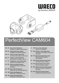
EN 23 Rear View Video Camera
Installation and operating manual
FR 36 Camera video de recul
Please read this instruction manual carefully before installation and first use, and store it in a safe place. If you pass on the product to another person, hand over this instruction manual along with it.
Contents
1 Explanation of symbols 23
2 Safety and installation instructions. 24
3 Scope of delivery 27
4 Accessories 27
5 Intended use 27
6 Technical description 27
7 Information on the electrical connections. 28
8 Mounting the camera 29
9 Cleaning and caring for the camera. 34
10 Guarantee 34
11 Disposal 34
12 Technical data 35
1 Explanation of symbols

CAUTION!
Safety instruction: Failure to observe this instruction can lead to injury.

NOTICE!
Failure to observe this instruction can cause material damage and impair the function of the product.

NOTE
Supplementary information for operating the product.
Action: This symbol indicates that action is required on your part. The required action is described step-by-step.
This symbol describes the result of an action.
Fig. 1 5, page 3: This refers to an element in an illustration. In this case, item 5 in figure 1 on page 3.
2 Safety and installation instructions
The manufacturer accepts no liability for damage in the following cases:
- Faulty assembly or connection
- Damage to the product resulting from mechanical influences and excess voltage
- Alterations to the product without express permission from the manufacturer
- Use for purposes other than those described in the operating manual
Please observe the prescribed safety instructions and stipulations from the vehicle manufacturer and service workshops.

NOTICE!
To prevent the risk of short circuits, always disconnect the negative terminal of the vehicle's electrical system before working on it. If the vehicle has an additional battery, its negative terminal should also be disconnected.

WARNING!
Inadequate supply cable connections could result in short circuits, which could have as a consequence that:
- Cable fires occur
The airbag is triggered - Electronic control devices are damaged
- Electric functions fail (indicators, brake light, horn, ignition, lights)
Please observe the following instructions:
-
When working on the following cables, only use insulated cable lugs, plugs and flat push-on receptacles:
-
30 (direct supply from positive battery terminal)
- 15 (connected positive terminal, behind the battery)
- 31 (return line from the battery, earth)
L (indicator lights left)
R (indicator lights right)
Do not use terminal strips.
- Use a crimping tool to connect the cables.
-
When connecting to cable 31 (earth), screw the cable
-
to the vehicle's earth bolt with a cable lug and a gear disc or
- to the sheet-metal bodywork with a cable lug and a self-tapping screw.
Ensure that there is a good earth connection.
If you disconnect the negative terminal of the battery, all data stored in the volatile memories will be lost.
- The following data must be set again, depending on the vehicle equipment options:
Radio code
- Vehicle clock
-
T i m e r
-
On-board computer
- Seat position
You can find instructions for making these settings in the appropriate operating instructions.
Observe the following installation instructions:

CAUTION!
- Secure the parts of the parking aid installed in the vehicle in such a way that they cannot become loose under any circumstances (sudden braking, accidents) and cause injuries to the occupants of the vehicle.
-
Secure any parts of the system covered by the bodywork in such a manner that they cannot be come loose or damage other parts and cables or impair vehicle functions (steering, pedals, etc).
-
Always follow the safety instructions of the vehicle manufacturer.
Some work (e.g. on retention systems such as the AIRBAG etc.) may only be performed by qualified specialists.

NOTICE!
- To prevent damage when drilling, make sure there is sufficient space on the other side for the drill head to come out.
- Deburr all drill holes and treat them with a rust-protection agent.
Observe the following instructions when working with electrical parts:

NOTICE!
- When testing the voltage in electrical cables, only use a diode test lamp or a voltmeter.
Test lamps with an illuminant take up voltages which are too high and which can damage the vehicle's electronic system.
-
When making electrical connections, ensure that:
-
they are not kinked or twisted
- they do not rub on edges
-
they are not laid in sharp edged ducts without protection.
-
Insulate all connections.
- Secure the cables against mechanical wear with cable binders or insulating tape, for example to existing cables.
The camera is watertight in accordance with IP69K. The seals on the camera can therefore withstand a high-pressure cleaner. Nevertheless, keep a distance of at least 50~cm between the nozzle of the high pressure cleaner and the camera.
Always observe the following instructions when handling the camera:
- Do not open the camera, as this impairs the sealing and the function of the camera (fig. 4, page 4).
- Do not pull at the cables, as this impairs the sealing and the function of the camera (fig. 5, page 4).
The camera is not suitable for submerged operation.
3 Scope of delivery
| No. in Quantity Description Item number fig. 6, page 5 |
| 1 1 CAM60ADR (compliant to ADR) 9102000065 |
| 2 1 Camera bracket 9102200166 |
| 3 2 Side covers |
| -- Fastening material |
4 Accessories
Available as accessory (not included in scope of delivery):
Description Item number
Heavy duty system cable 20m , compliant to ADR 9102200071
5 Intended use
The CAM60ADR camera (item no. 9102000065) is designed primarily for use in vehicles under extreme conditions. It can be used in video systems to observe the space around the vehicle from the driver's seat when manoeuvring or parking, for example.
CAM60ADR is compliant to ADR and can be used in vehicles for transport of hazardous goods.

WARNING!
Risk of injury!
Since rear view systems are designed merely as an additional aid for reversing, it does not relieve you of the duty to take proper care when reversing.
6 Technical description
The camera with integrated microphone, which is encased in aluminium housing, transmits image and sound to a monitor via a cable. The infrared LEDs improve night vision.
The camera transmits the image as if you are looking in the rear mirror.
The camera consists of the following main elements:
| No. in fig. 7, page 5 | Description |
| 1 | 6-pin connection cable |
| 2 | Infrared LEDs |
| 3 | Microphone |
7 Information on the electrical connections
7.1 Laying cables

NOTICE! Risk of damage!
- To prevent damage, when drilling ensure that there is sufficient space on the other side for the drill head to come out.
- Cables and connections which are not properly installed will cause malfunctions or damage to components. Correct installation of cables and connections is the basic prerequisite for lasting and trouble-free operation of the retrofitted components.
- The cables may not be exposed for long periods to solvents such as benzine, as the solvents can damage the cable.
Please observe the following instructions:
- As far as possible, use original openings or alternative openings for the connecting cable duct, e.g. the paneling edges, ventilation grilles or blank panels. If no openings are available, you must drill holes for the cables. Check beforehand that there is sufficient room for the drill head to come out on the other side.
-
Wherever possible lay cables inside the vehicle, as they are better protected inside than outside the vehicle. If you do need to lay a cable outside the vehicle, ensure that it is well secured (use additional cable ties, insulating tape, etc.).
-
To prevent damage to the cables, when laying them ensure that there is sufficient distance to hot or moving vehicle components (exhaust pipes, drive shafts, light systems, fans, heater etc.). Use corrugated piping or other protective materials to protect against mechanical wear.
- Screw on the plug connections of the connecting cables to protect against water penetration (fig. 15, page 7).
-
When laying electric connections, ensure that
-
They are not kinked or twisted
- They do not rub on edges
-
They are not laid in sharp edged ducts without protection (fig. 3, page 4)
-
Attach the cables securely in the vehicles to prevent tripping hazards.
Use cable binders, insulating tape or glue the cables in place. - Protect every through-hole made in the bodywork against water pene
tration, e.g. by using a cable with a sealant and by spraying the cable and
the the cable sleeve with sealant.

NOTE
Do not start sealing the through-holes until all installation work
has been finished for the camera, and the required cable lengths
have been established.
8 Mounting the camera
8.1 Tools required
For installation and assembly you will require the following tools:
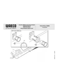
- Drill bit set (fig. 1, page 3)
- Drill (fig. 1 2, page 3)
- Screwdriver (fig. 1 3, page 3)
- Set of ring or open-ended spanners (fig. 1 4, page 3)
- Measuring ruler (fig. 1 5, page 3)
- Hammer (fig. 1 6, page 3)
- Centre punch (fig. 17, page 3)
To make and test the electrical connection, the following tools are required:
- Diode test lamp (fig. 1 8, page 3) or voltmeter (fig. 1 9, page 3)
Insulating tape (fig. 1 11, page 3) - Cable bushing sleeves, if necessary
To fasten the cables you may require additional cable binders.
8.2 Mounting the camera

CAUTION!
Select a location for the camera and attach it so securely that it cannot under any circumstances fall off and injure bystanders (e.g. by being knocked off by branches brushing over the roof of the vehicle).

NOTE
If installing the camera alters the vehicle height or length specified in the vehicle documents, your vehicle must be inspected by the appropriate authorities.
Make sure that you are in possession of documents verifying that your vehicle has passed this inspection.
Observe the following installation instructions:
- To provide a suitable viewing angle, the camera must be attached at a height of at least 2m .
Ensure that you have a firm place from which to work when mounting the camera. - Ensure that the installation location of the camera is sufficiently firm (e.g. to prevent the camera from being knocked down by branches that may brush over the roof of the vehicle).
-
Mount the camera bracket horizontally and in the middle of the rear of the vehicle (fig. 8, page 6).
-
The most secure type of attachment is with screws fitted through the body. Please observe the following instructions:
-
There must be sufficient space for the mounting procedure behind the chosen installation location.
- Suitable measures must be taken to prevent water penetrating through any holes made (e.g. by using screws and sealant and/or spraying the outer attachment parts with a sealant).
-
The location on the body where you wish to attach the camera must be rigid enough to allow the camera to be tightly fastened.
-
Check beforehand that there is sufficient room for the drill head to come out on the other side (fig. 2, page 4).
- If you are not sure about the location you have chosen, consult the vehicle manufacturer or dealer.

NOTE
We recommend greasing the threads of the bolts to prevent corrosion.
When mounting the camera, proceed as follows:
Hold the camera on the chosen location and mark at least two different points for the drill holes (fig. 9, page 6).
Using a hammer and centre punch, gently pre-punch the previously marked points to prevent the drill head from slipping off.
If you want to screw on the camera with self-tapping screws
(fig. 10, page 6)

NOTICE! Risk of damage!
The holder may only be attached to steel panels with a minimum thickness of 1.5mm using self-tapping screws.
Drill 4 mm holes at the points you have just marked.
Deburr all drill holes and apply rust-protection.
Screw the camera bracket on with the 5 × 20 ~mm self-tapping screws.
If you would like to attach the camera with threaded screws fitted through the construction (fig. 11, page 6)

NOTICE! Risk of damage!
Ensure that nuts cannot be pulled through the body shell when they are tightened.
Use larger washers or metal plates if necessary.
Drill 6.5mm holes at the points you have just marked.
Deburr all drill holes and apply rust-protection.
Screw the camera bracket on with the M5 x 20 mm threaded screws. Depending on the thickness of the construction, you may require longer threaded screws.
Creating a through-hole for the camera connection cable (fig. 12, page 6)

NOTE
If possible, use available openings – such as ventilation grilles – to feed the connection cables through. If there are no existing openings, you must drill a hole with a 16 mm diameter.

NOTICE! Risk of damage!
Ensure that there is sufficient space on the other side for the drill head to come out
Drill a hole of 16mm near the camera.
Deburr all drill holes that have been made in the sheet metal and apply rust-protection.
Place cable sleeves in all sharp edged ducts.
Mounting the camera

NOTICE! Risk of damage!
Only use the screws supplied to mount the camera in the camera bracket. Longer screws will damage the camera.
Push the camera into the camera bracket.
Attach the camera loosely with the two screws M3 x 8 mm in the slots (fig. 13, page 6).
Align the camera provisorily so that the lens is at an angle of approx. 50^ to the perpendicular axis of the vehicle (fig. 14, page 7).

NOTICE! Risk of damage!
Never mount the camera without the camera guard.
Connecting the camera

NOTE
- Lay the camera cable so that should you need to remove the camera, you can access the plug connection between the camera and the extension cable easily. This considerably eases dismantling work.
- To minimise corrosion in the plug, apply a small amount of grease – such as pin grease – inside the plug.
Additional extension cables are available on request (see "Accessories" on page 27).
Guide the camera cable into the vehicle interior.
Insert the plug of the camera cable into the socket of the extension cable.
Screw on the plug connections of the connecting cables to protect against water penetration (fig. 15, page 7).
Aligning the camera

NOTE
If necessary before aligning the camera connect the camera to a monitor and to a power supply (see connecting diagram, fig. 16, page 7
Use the monitor image to align the camera:
The monitor image should show the bottom edge of the rear or the bumper of your vehicle (A). The middle of the bumper should be in the middle of the screen. (fig. 17, page 7).
Check the function of the camera after you have connected it to a monitor.
Fastening the camera
Thighten the two screws in the slots of the camera bracket.
Mount the side covers with the two screws M3 x 8 mm in the middle drill holes (fig. 18, page 8).
9 Cleaning and caring for the camera

NOTICE! Risk of damage!
Do not use sharp or hard objects to clean the device as these may damage the device.
Clean the camera with a soft, damp cloth from time to time.
10 Guarantee
The statutory warranty period applies. If the product is defective, please contact the manufacturer's branch in your country (see the back of the instruction manual for the addresses) or your retailer.
For repair and guarantee processing, please send the following items:
Defect components
A copy of the receipt with purchasing date
A reason for the claim or description of the fault
11 Disposal
Place the packaging material in the appropriate recycling waste bins wherever possible.
If you wish to finally dispose of the product, ask your local recycling centre or specialist dealer for details about how to do this in accordance with the applicable disposal regulations.
12 Technical data
| PerfectView CAM60ADR | |
| Item no.: 9102000065 | |
| Image sensor: 1/3" CCD | |
| Pixels: Approx. 290,000 pixels | |
| Video standard: PAL, 1 Vpp | |
| Sensitivity: < 0.5 lux | |
| Viewing angle: Approx. 69° vertical | Approx. 92.5° horizontal Approx. 120° diagonal |
| Operating voltage: 11 – 16 V== | |
| Consumption: 4.8 W | |
| Operating temperature: -30 °C bis +70 °C | °C |
| Protection class: IP69K | |
| Vibration resistance: 10 g | |
| Dimensions W x H x D (with bracket): | 80 x 75 x 62 mm |
| Weight: | Approx. 0.3 kg |
Approvals
The device has E13 certification.

6 Description technique
PASS PAI Fare for skade!
HeyoBtBOpTeIbHoe npcoeINHeHne npOBOmKet npNBeCTn K TOMy, yTO BCJeDCTBnE KOPOTKOrO 3aMbIkaHnA
- BO3HnKaeT BO3rOpaHne Ka6eJe,
- cpa6aTbIbAeT NaDyBna NodyuKa 6e3OnacHocTn,
- NOJyauot NOBpeKdEHNr 3JIeKTPoHHbIe yCTpoiCtBa ynpaBJeHnra,
- BbIXOJrT n3 CTrPOr 3JIeKTPnueCKNe ΦyHKcN (yKa3aTeIIN NOBOpOra, CNHaI TOpMOxKeHnR, 3ByKOBoi CNHaI, 3axnRaHne,OCBeUeHne).
TOMy co6noidaTe cneyuOne yka3aHna:
-
Исторы пapi раоб tax на следуюцх Линях Толбко Исторовниные Кабелные зжимbl, Шт ekрbl и Нарухнibles Шт ekрbl:
-
30 (Bxod noIoxntbHoro noIoxntbHoro noIoca baTapeu, npraMo)
- 15 (ВКПЮЧЕHHын NOLOЖNTeJIbHbI NOJIOC, 3a aKKyMyJЯTOpHOJ 6aTaapee)
- 31 (obpatnae b ot akymyjtohpno 6atapen, kopnyc)
L (IeBbIe 0oHApn yka3aTeNei nobopoTa)
R (npabblie oohapny yka3aTeJei nobopoTa)
He nCNoIb3yIe KJIeMMOBbie KOJODKn.
-Дя coeHHeHЯ ka6eIe nCnoB3yIte o6xIMHbIe KneI.
- Ппвnttekaбьл пи соeненях к npobody 31 (kopnyc)
C NOMOJIbIO Ka6eJIbHOrO 3aXIMa I 3y6uToI npyJINHOJ WaIBI K BnHTy IJIa COeDInHeHnA C KopnycOM, IMeIoUeMycr Ha aBTOMoBnJIe INI
C NOMOU KabeJIbHOro 3aXIMa N CaMOHaPe3aHooIero BnHTa K JInCTy Ky3OBA.
ObecneuBaTe xopoWee coeHHeHne c Kopnycom!
Pn OTCoeHHeHn KJIeMMbI OTPuCaTeNbHOro NOnIOca aKKyMylrTopHO 6aTapeN BCE 3HepeO3aBnCmMbIe 3aONMHaUoIe yCTpoiCTBa 3JeKTPoHNKn CnCTem KOMΦOpTa TepaHT COxpaHeHHbIe B HIX DaHHbIe.
B 3aBnCmOCTn OT OChaSeHnA bTOMo6nJ, Bam npIeTc 3aHOBO Hactpontb CJIeKyuOuNe DaHHbIe:
- KoD paAnOpnemHnka
- Yacbl aBTOMO6nJIa
-TaHmep
-Boptoboi KOMnbIOTep - PtoJoxKeHne cndeHn
Yka3aHnI NO HAcTpoNKe npNBedeHbIB COOTBETCTByOUsEi NHCTpyKcNl N0 3KcNPyTaCNI.
Pn moTaxe co6IouaIte cIeDyUoIne yka3aHna:

OCTOPOXKHO!
KpeHnTe yCTaHOBJIeHHbIe B aBTOMOBJIe DeTaJIb TaK, YTO6bl OHn Hn npN KaKNX ycNoBnX (pe3KOM TOpMOJKeHN, aBaPn) He MOrJN OTCOeDINHTbcra, Tem CaMbIM npHBODa K TpaBMam IaccKaHIpOB.
KpeHnTe cKpbItbIe, yCTaHaBnBaemble nOd oBswBkoJ deTaJIncCTeMbI TaK, YTObI OHN He MOrI N OTCoEINHTbcra IIN NOBpeDITb dpyrHe DeTaN IN npOBoDa HApUwNTb cyHKcNn ABTomO6nna (pyneBoe ynpabLeHne, neJaN n T. n.).
Bcerda co6nIouaTe yka3aHnI n3rotOBNTeJI aBTOMObII naTexHnke 6e3oNaChOCTn.
HekotopbIe pa6oTbI (Ha npimep, Ha cnCTeMax 6e30nacHOCTN, B T. Y. Ha NaYBbIX NODyKkax 6e30nacHOCTN) pa3peWaeTcR BBIOJHrTb TOJIbKO O6UyeHHOMy NepcoHany.

BHIMAHHE!
Bo n36eXaHne noBpeXdEHN npn CBePJIeHN cIeIte 3a doCTaTOUHbIM CBO6OHDbIM npocTpaHCTBOM dJa BbIXOda CBepJa.
3aunCTte BCE OTBepCTnI n CmaXbTe nx aHTNKoppo3nOHbIM cpeDCTBOM.
Ipn pa6oTax Ha 3JIeKtpnuecko cnCTeme co6JIHOaIte cIeDyUOuNe yKa3aHnra:

BHUMAHNE!
He neperei6aIncb n He cKpyuNbAInscb,
He TepJIncb O KpOMKn,
He npoknaIbIbIaJInc6e3 3aIITbI Yepe3 BBOdbI, IMeIOUne OCTpbIE KpOMKn.
3aun3oJnpyteBceIHHNIOeDnHeHna.
- Празхапгудддддддддддддддддддддддддддддддддддддддддддддддддддддддддддддддддддддддддддддддддддддддддддддддддддд徴сь
- Доступынчо Кабел OT Мханчecнх Harpy3OK, 3aФИКСИРовав IX Кабелньим NTяжками Ил N3ОЛЯЦИНГОЛЕHTОД, habример, 3a Имeoциеся Лини.
Kamepa YBnraTcB OdoHepOnucaemO cornaCHO cTepeH 3aunIb IP69K. YNIOHTHeHNA KamepbI, TaKIM o6pa3OM, TaKKe BbldePknBaOT OunchKy BblCOKm DabJIeHNEM. HecMOTpHa 3TO, paCtOJHne MeJy CoNlOM OunchTeJIY BblCOKOro DabJIeHNA IN Kamepoi He DoJXHO 6bITb MeHbSe npImepHo 50 cm.
CobIIOdaIe Te TEM He MeHee cIeDyUoIe yka3aHnNo o6paueHnO cKamepoi:
He BCKpbIbAaTe KaMepy, T. K. 3TO OTPncaTeNbHO cKa3bIbAeTcra Ha repMeTNUHOCTN pa6OTocNOC6HOctn (pnc. 4, cTp. 4).
He TAHNTe 3a Ka6eHn, T. K. 3TO OTPuCaTeJbHo cKa3bIbAeTcHa repMeTuHocTN pa6OTocNOC6HOCTn KaMepbl (pnc. 5, Ctp. 4).
Kamepa He npirodHa dJa pa6OtI NOBOD.
3 O6bem nocTaBKn
Dulcik (obr. 17, strana 3)
Dometic Australia Pty. Ltd.
1 John Duncan Court
Varsity Lakes QLD 4227
+61755076000
+61755076001
Mail: sales@dometic-waeco.com.au
AUSTRIA
Dometic Austria GmbH
Domatic Plc. Sales Office
Kérékgyarto u.5.
H-1147 Budapest
+3614684400
+3614684401
Domatic Italy S.r.l.
Via Virgilio, 3
I-47100 Forli
+390543754901
+390543756631
Mail: info@dometic.it
NORWAY
Dometic Norway AS
Skolmar 24
N-3232 Sandefjord
+4733428450
+4733428459
Mail: firmpost@waeco.no
POLAND
Dometic Poland Sp. z o.o.
Ul. Puławska 435A
02-801 Warszawa
Poland
+48224143200
+48224143201
Mail: info@dometic.pl
RUSSIA
Dometic RUS LLC
Komsomolskaya square 6-1
107140 Moscow
Russia
+74957807939
+74959165653
Mail: info@dometic.ru
SLOVAKIA
Domatic Slovakia s.r.o.
Tehelná 8
SK-98601 Filakovo
+421474319107
+421474319166
Mail: info@dometic.sk
SPAIN
Dometic Spain S.L.
Avda. Sierra del Guadarrama, 16
E-28691 Villanueva de la Canada
Madrid
+34 902 111 042
+34900100245
Mail: info@dometic.es
SWEDEN
Dometic Scandinavia AB
Gustaf Melins gata 7
Dometic Switzerland AG
Riedackerstrasse 7a
CH-8153 Rümlang (Zürich)
+41448187171
+41448187191
Mail: info@dometic-waeco.ch
TAIWAN
WAECO Impex Ltd.
Taipei Office
2 FL-3 · No. 56 Tunhua South Rd, Sec 2
Taipei 106, Taiwan
+886227014090
+886227060119
Mail: marketing@dometic-waeco.com.tw
UNITED KINGDOM
Domatic UK Ltd.
Dometic House · The Brewery
Blandford St. Mary
Dorset DT11 9LS
+448446260133
+448446260143
Mail: sales@dometic.co.uk
UNITED ARAB STATES
Dometic Middle East FZCO
P.O.Box 17860
S-D 6, Jebel Ali Freezone
Dubai, United Arab Emirates
+97148833858
+97148833868
Mail: info@dometic.ae
UNITED STATES OF AMERICA
Dometic Marine Division
2000 N. Andrews Ave. Extension
Pompano Beach, FL 33069 USA
+19549732477
+19549794414
Mail: marinesales@domesticusa.com