
RET 230 HCW3 - Thermostat DANFOSS - Free user manual and instructions
Find the device manual for free RET 230 HCW3 DANFOSS in PDF.
| Product Type | Thermostat for 2-pipe systems with forced-air evaporator |
| Brand | Danfoss |
| Model | RET 230 HCW3 |
| Dimensions (L x H x D) | 110 x 90 x 40 mm |
| Power supply | 230 VAC ± 15%, 50/60 Hz |
| Temperature range (heating) | 5 to 30 °C |
| Switching temperature (heating → cooling) | > 30 °C (flow temperature) |
| Switching temperature (cooling → heating) | < 16 °C (flow temperature) |
| Relay outputs | 2 x SPST, 3(1)A, 10-230 VAC, type 1B |
| Temperature accuracy | ± 1 °C |
| Manufacturing standards | EN 60730-2-9 |
| Rated impulse voltage | 2.5 kV |
| Ball pressure test | 75 °C |
| Recycling level | Grade 2 |
| Main functions | Motorized valve control, automatic heating/cooling switchover, manual fan speed selector, off/auto thermostat selector |
| DRC switches | On/Off (all or nothing) or Chrono (3 or 6 cycles per hour), Celsius/Fahrenheit |
| Installation | Recommended height 1.5 m from the floor, clearance of 50 mm above and 100 mm below, by a qualified electrician |
| Dial locking / limitation | Locking springs at the back of the knob |
| Maintenance and cleaning | Clean with a soft dry cloth; do not use abrasive products or solvents |
| Safety | Installation reserved for a qualified electrician; comply with applicable IEEE wiring regulations |
Frequently Asked Questions - RET 230 HCW3 DANFOSS
• Switch 4: On/Off (all or nothing mode) or Chrono (proportional mode for heating).
• Switch 3 (if switch 4 is on Chrono): 3 cycles of 20 min or 6 cycles of 10 min per hour.
• Switch 2: Celsius (°C) or Fahrenheit (°F) scale.
• Switch 1: not used.
User questions about RET 230 HCW3 DANFOSS
0 question about this device. Answer the ones you know or ask your own.
Ask a new question about this device
Download the instructions for your Thermostat in PDF format for free! Find your manual RET 230 HCW3 - DANFOSS and take your electronic device back in hand. On this page are published all the documents necessary for the use of your device. RET 230 HCW3 by DANFOSS.
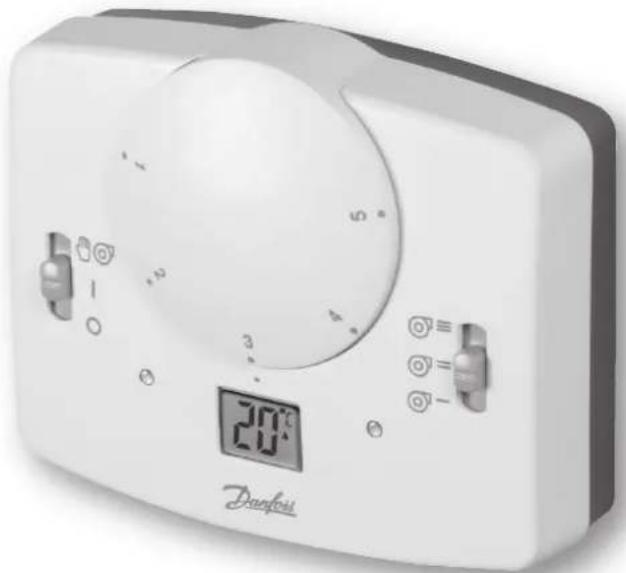
USER MANUAL RET 230 HCW3 DANFOSS
Electronic Heat / Cool thermostat with auto-changeover based on water temperature

Installation Instructions User Instructions

Installation Instructions 3-9
User Instructions 10

Installation Instructions

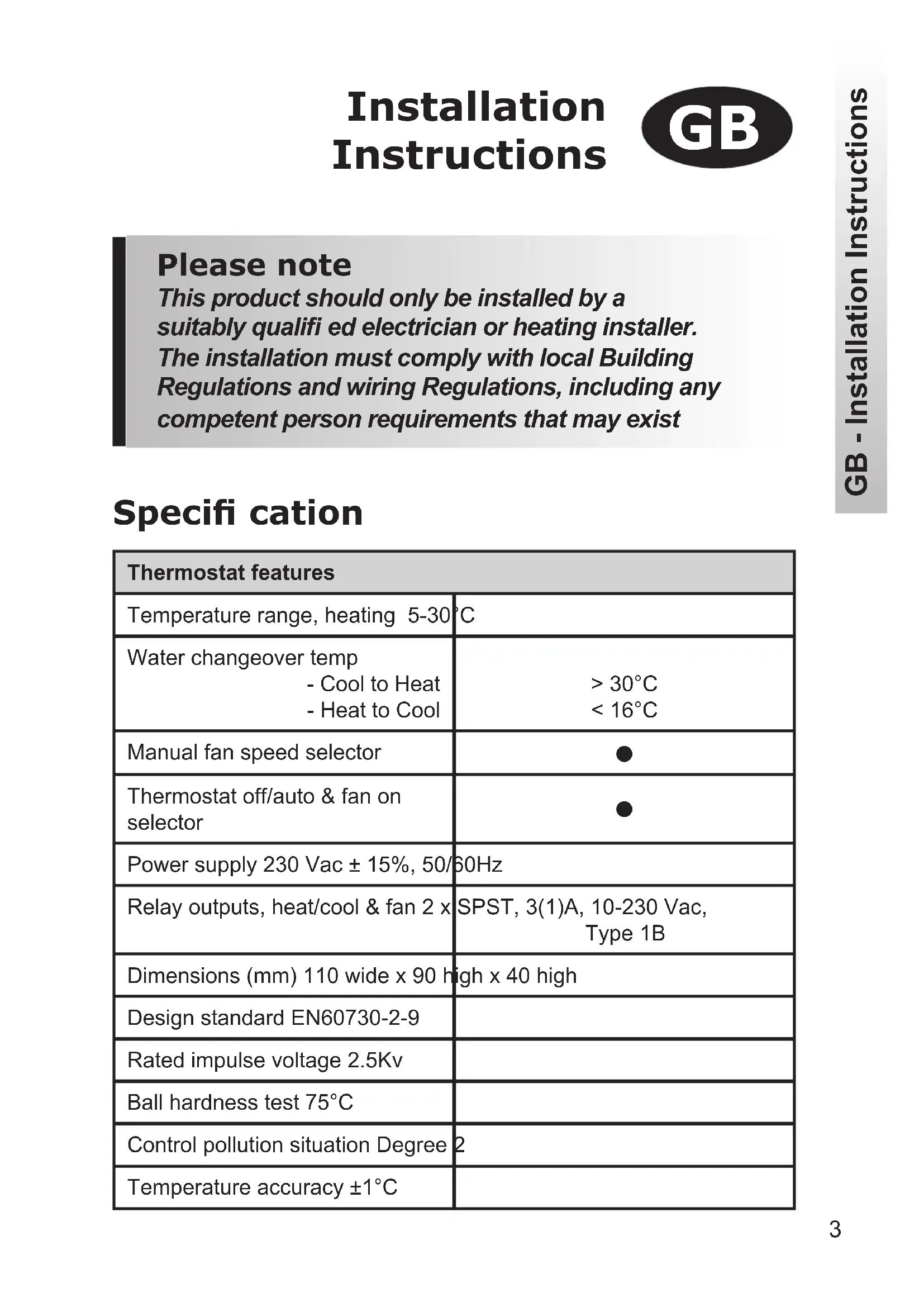
Please note
This product should only be installed by a suitably qualified electrician or heating installer. The installation must comply with local Building Regulations and wiring Regulations, including any competent person requirements that may exist
Specification
| Thermostat features | |
| Temperature range, heating 5-30°C | |
| Water changeover temp - Cool to Heat - Heat to Cool | >30°C <16°C |
| Manual fan speed selector | ● |
| Thermostat off/auto & fan on selector | ● |
| Power supply 230 Vac ± 15%, 50/60Hz | |
| Relay outputs, heat/cool & fan 2 x | SPST, 3(1)A, 10-230 Vac, Type 1B |
| Dimensions (mm) 110 wide x 90 high x 40 high | |
| Design standard EN60730-2-9 | |
| Rated impulse voltage 2.5Kv | |
| Ball hardness test 75°C | |
| Control pollution situation Degree 2 | |
| Temperature accuracy ±1°C | |
Product overview
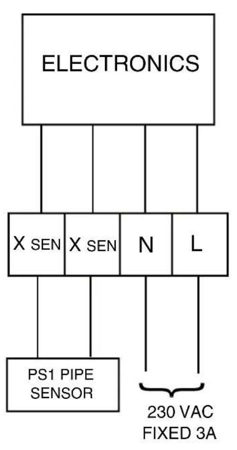
The thermostat is designed for use in systems equipped with fan coils served by a 2-pipe central changeover system. The thermostat controls the operation of a motorized valve which, during heating periods, opens when heat is required and which, during cooling periods, opens when cooling is required.
The changeover from heating to cooling is achieved automatically by measuring the temperature of the flow pipe. If the flow temperature exceeds 30^ the thermostat operates as a heating thermostat, if the flow temperature is less than 16^ the thermostat operates as a cooling thermostat
Important note: It is essential that the circuit in which the pipe sensor is located is not closed off and that water circulates past the sensor at all times. This may require the fitting of a bypass valve between system flow and return at the end of each circuit.
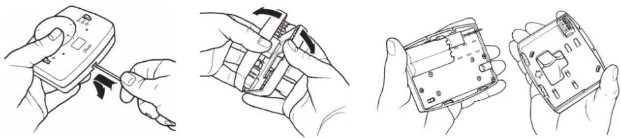
Installation
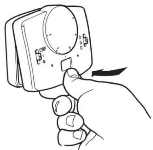
First remove the wallplate from the back of the unit.
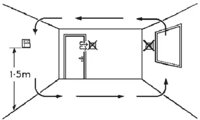
- Ensure that there is a minimum of 50mm above the unit and 100mm below the unit in order to mount the plug-in module.
Fix at a height of approximately 1.5m from the floor, away from draughts or heat sources such a fan-coil outlets, sunlight or offi ce equipment.
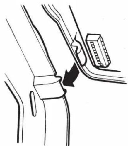
Pipe sensor location
Fix the pipe sensor to the flow pipe using the clamping band supplied.
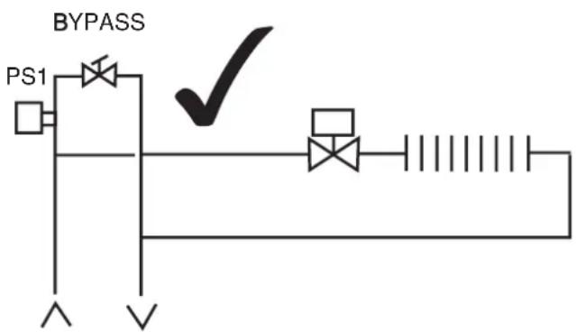
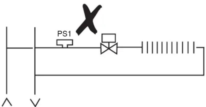
Important note: It is essential that the circuit in which the pipe sensor is located is not closed off and that water circulates past the sensor at all times when the system is in operation. This may require the fitting of a bypass valve between system flow and return to ensure circulation past the sensor.
2-pipe fan coil application
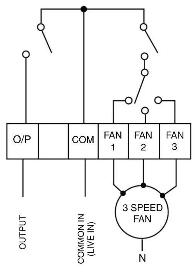
Note:
If HEAT/COOL/FAN outputs are 230V, link terminals L-COM
Commissioning
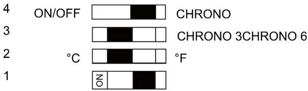
Prior to re-fi tting the thermostat to the wallplate, the DIL switches on the rear of the unit must be set to the desired setting.

DIL Switch options, shown in factory set position.
Sw On
DIL Switch descriptions
Switch 4: If set to On/Off, both heating and cooling stages operate in on/off mode. If set to Chrono, heating stage operates in chrono-proportional modes, cooling continues in On/off mode
Switch 3: Active only if switch 4 is set to Chrono. This switch determines the number of cycles per hour that the thermostat will impose on the system, the options are three 20 minute cycles or six 10 minute cycles
Switch 2: Allows Celsius or Fahrenheit temperature scaling to be selected
Switch 1: Not used in this model
Mounting thermostat to the wallplate
To mount the thermostat to the wallplate, align the tabs on the top of the thermostat with the apertures in the wallplate and hinge the thermostat down, pressing firmly to engage the securing clip in the wallplate.
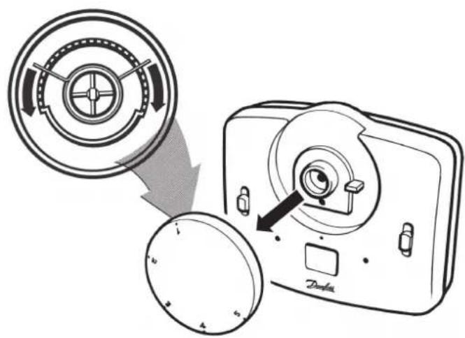
Locking & limiting
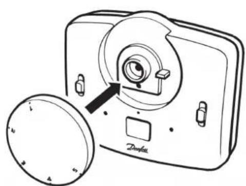
To lock or limit the setting range turn the setting dial to 3 and remove knob.
Position the locking springs on the rear of the dial to the desired position and re-mount the knob ensuring that number 3 on the dial aligns with the reference mark on the case.
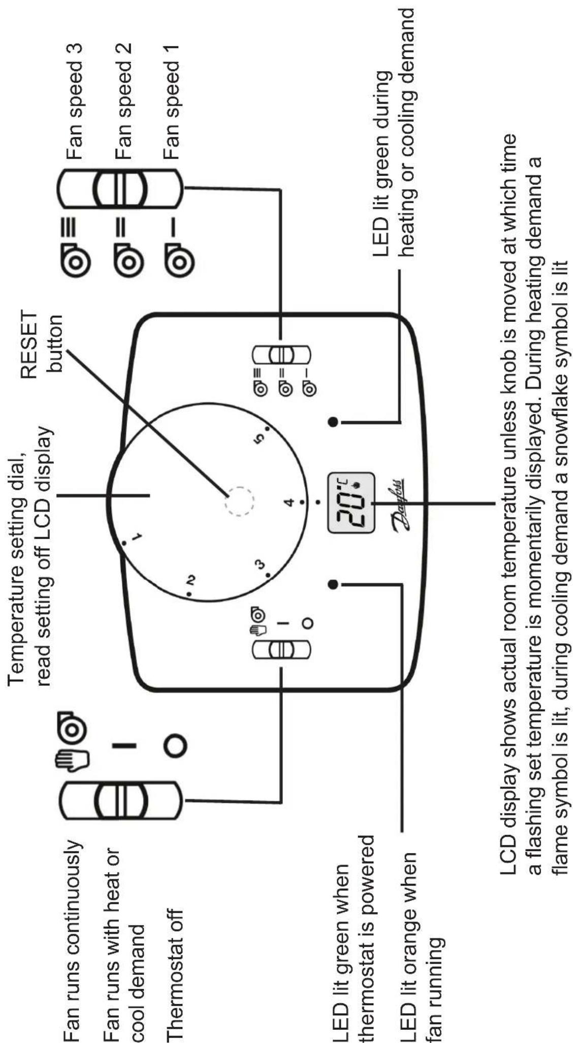
Note: Should it be necessary to reset the microprocessor for any reason, a reset button is located beneath the setting dial. Use a non-metallic point, for example a matchstick, to depress the recessed button.
www.danfoss.com/BusinessAreas/Heating
This product complies with the following EC Directives:
Electro-Magnetic Compatibility Directive.
(EMC) (89\336\EEC), (92\31\EEC)
Low Voltage Directive.
(LVD) (73\23\EEC), (93\68\EEC)
CE

Brand : DANFOSS
Model : RET 230 HCW3
Category : Thermostat