
RFZ - Thermostat ZEHNDER - Free user manual and instructions
Find the device manual for free RFZ ZEHNDER in PDF.
| Product type | Wireless remote control for ventilation system |
| Compatible models | CMFe R, WHR RF, ComfoAir RF, ComfoD RF, Santos RF |
| Power supply | CR2032 lithium battery |
| Battery life | Approximately 5 years (10 actions/day) |
| Buttons | 4 buttons: Positions 1, 2, 3, and Timer |
| Timer | Short press: 10 min at position 3; long press (>2s): 30 min at position 3 |
| Range | Wireless (RF) - standard range (not specified) |
| LED indicators | 2 LEDs (red/green) to indicate operating status and programming |
| Wall mounting | By screws and wall plugs or adhesive strips (on smooth non-metallic surface) |
| Package contents | 1 remote control, 1 CR2032 battery, 2 adhesive strips, 2 screws, 2 wall plugs, 1 manual |
| Maintenance | Clean with a dry cloth; replace battery if necessary |
| Battery disposal | Do not dispose of with household waste, deposit at collection point |
| Programming | Pairing with the ventilation unit receiver |
| Warranty | Not specified |
Frequently Asked Questions - RFZ ZEHNDER
User questions about RFZ ZEHNDER
0 question about this device. Answer the ones you know or ask your own.
Ask a new question about this device
Download the instructions for your Thermostat in PDF format for free! Find your manual RFZ - ZEHNDER and take your electronic device back in hand. On this page are published all the documents necessary for the use of your device. RFZ by ZEHNDER.
USER MANUAL RFZ ZEHNDER
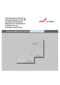
The CMFe R, WHR RF, ComfoAir RF, ComfoD RF and Santos RF can be operated remotely using a transmitter (RFZ). This has 4 buttons for setting the fan position. Position 1, position 2, position 3 and a time delay.
Before the receiver in the ventilation unit can be operated remotely, the transmitter(s) and receiver must be tuned to each other. The receiver can easily be retro-fitted to a ventilation unit without standard RF control. Once the 3-position switch / receiver combination has been fitted, the highest activated rpm is the benchmark. The receiver can simply be affixed or screwed to the wall.
The remote control is powered by a lithium battery (type: CR 2032). A new battery has a lifespan of about five years with a maximum of ten switch movements daily. Of course, the more often it is used, the shorter the lifespan.
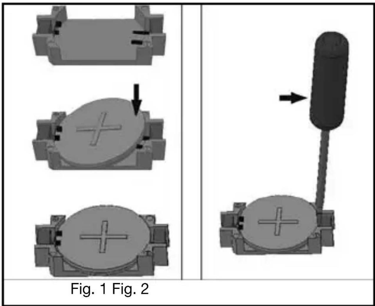
Inserting the battery
Note: The cordless switch does not work if the battery has been fitted incorrectly. An incorrectly fitted battery can damage the electronics.
The battery must be fitted at the back of the switch. Insert the battery on the (+) side of the holder with the engraved plus (+) facing up, and then push the battery in place on the (-) side (fig. 1).
Battery replacement
Lift the battery out of the holder on the (-) side by means of a screwdriver (fig. 2). Saved functions are retained during battery replacement.
Note: Do not throw empty batteries out with the household refuse, but take them to your nearest collection point for chemical refuse.
Assembly
- Use the screws supplied to fit locking plate A (fig. 3) to a flush outlet, or directly onto the wall using the screws and plugs. The 'TOP' marking should be visible at the top end of the locking plate.
You can also affix locking plate A (fig. 4) onto a smooth/level surface (no metal surface) by means of the self-adhesive strips (D).
- Place cordless switch C (fig.5) into frame B, until it clicks into position.
- Place the cordless switch and frame approx. 5 mm above locking plate A and lower it until it clicks tight into the fastening lugs of the locking plate. (fig.6)
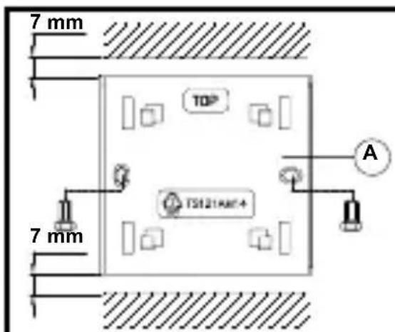
Fig 3.
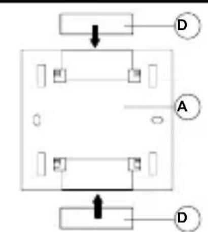
Fig 4.
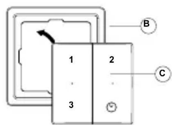
Fig 5.
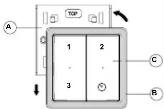
Fig 6.
Demounting
Fastening lugs hold the frame securely in the locking plate. Never pull the frame off without first lifting it upwards, otherwise you could damage the locking plate. (fig.7)
- Slide the cordless switch and frame upwards by approx. 5 mm.
- Now remove the switch and frame.
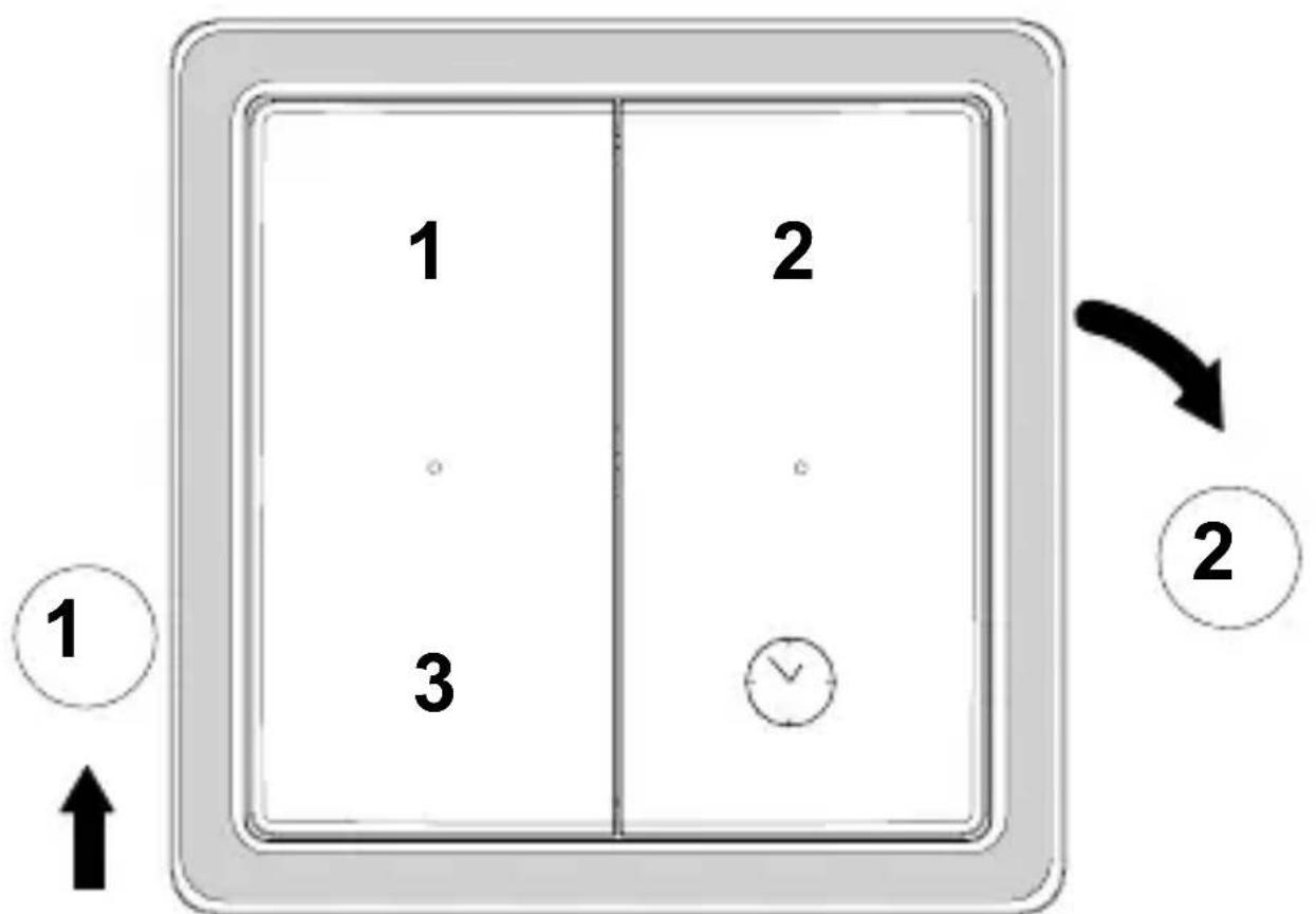
Fig.7
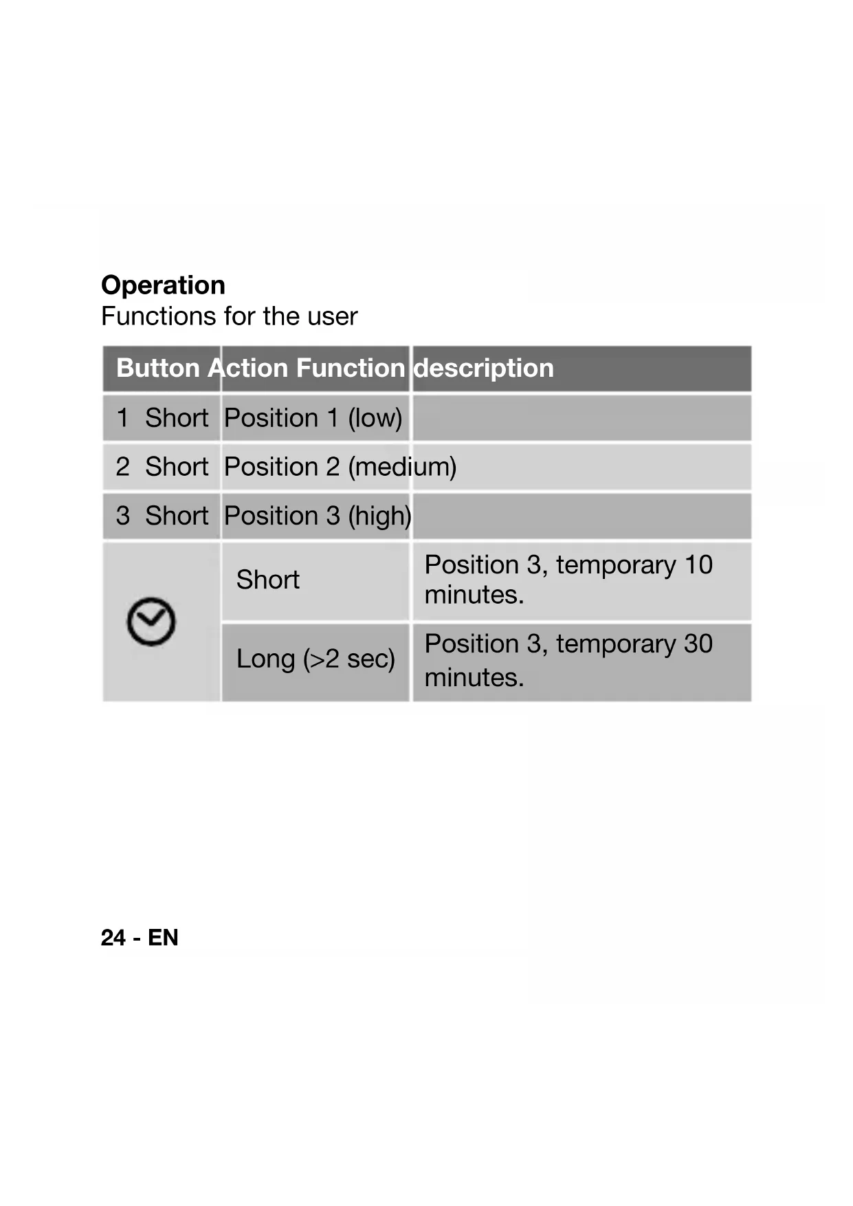
Operation
Functions for the user
| Button Action Function description | ||
| 1 Short | Position 1 (low) | |
| 2 Short | Position 2 (medium) | |
| 3 Short | Position 3 (high) | |
| ⊗ | Short | Position 3, temporary 10 minutes. |
| Long (>2 sec) | Position 3, temporary 30 minutes. | |
24 - EN
Functions for the fitter
Tuning the ventilation unit to the RFZ switch
As standard, 1 or more switches on 1 ventilation unit
- Disconnect the ventilation system and then switch the power back on. You now have 10 minutes to program the unit.
- Press "1" + button " " for at least 6 sec.
- Both indicators turn red and then green. Tuning is complete. (the switch receives the address of the ventilation unit)
- Test the 3 settings after programing the switch. For a second switch or further switches: repeat steps 1 to 4.
Multiple ventilation units on 1 switch.
- Disconnect the ventilation system and then switch the power back on. You now have 10 minutes to program the unit.
- Press “2” + button “ ” for at least 6 sec.
- Both indicators turn red and then green. Tuning is complete. (the ventilation unit receives the address of the switch)
- Test the 3 settings after programing the switch. For a second ventilation unit or further units: repeat steps 1 to 4.
Ventilation unit on 1 switch with an arbitrary address.
-
Disconnect the ventilation system and then switch the power back on. You now have 10 minutes to program the unit.
-
Press "3" + button " " for at least 6 sec.
- Both indicators turn red and then green. Tuning is complete. (the ventilation unit R receives an arbitrary address of the switch)
- Test the 3 settings after programing the switch.
LED indications
Left LED briefly lights up green: the ventilation unit has been set in position 1 or 3.
Right LED briefly lights up green: the ventilation unit has been set in position 2 or temporarily in position 3.
- Both LEDs light up red for 1 second: after a number of attempts, the ventilation unit has still not reacted.
- Both LEDs light up alternately red: The switch is in the fine-tune mode but the ventilation unit is not. Fine-tuning is therefore not possible. This alternate flashing continues for approx. 1 minute.
- Both LEDs light up green for 1 second: Tuning is complete.
Lieferumfang

- Inserting the battery
- Battery replacement
- Assembly
- Demounting
- Operation
- Functions for the fitter
- Tuning the ventilation unit to the RFZ switch
- As standard, 1 or more switches on 1 ventilation unit
- Multiple ventilation units on 1 switch.
- Ventilation unit on 1 switch with an arbitrary address.
- LED indications
- Lieferumfang
Brand : ZEHNDER
Model : RFZ
Category : Thermostat