
CO2 RF - Thermostat ZEHNDER - Free user manual and instructions
Find the device manual for free CO2 RF ZEHNDER in PDF.
| Product type | CO₂ ventilation regulator with thermostat |
| Brand | Zehnder |
| Model | CO2 RF |
| Supply voltage | 230 V ± 10 %, single phase, 50 Hz |
| Power consumption | Typical < 1 W |
| Minimum ambient temperature | -10 °C |
| Maximum ambient temperature | +40 °C |
| Air humidity (continuous) | 85 % without condensation |
| CO₂ measurement range | 400 - 2000 ppm |
| Sensor fault | Measured value < 300 ppm or > 10000 ppm |
| CO₂ target value | 1050 ppm |
| Output signal | 0-100 % RF, proportional |
| Protection class | II (EN60730-1) |
| IP protection rating | IP30 (EN60529-1) |
| Regulator type | RS type 1 |
| Ventilation modes | 4 positions: Absent, Present, Maximum, Auto CO₂ |
| CO₂ LED indicators | Green (< 1200 ppm), Orange (1200-1500 ppm), Red (> 1500 ppm) |
| Connection | Wireless RF with the ventilation unit |
| Installation | Flush mounting in standard box |
| Extension sensor | Optional, CO₂ measurement only |
| Warranty | 24 months after installation, 30 months after manufacture |
| Maintenance | Cleaning of air slots if necessary |
| Safety | Disconnect before intervention; protection against electrostatic discharges |
Frequently Asked Questions - CO2 RF ZEHNDER
User questions about CO2 RF ZEHNDER
0 question about this device. Answer the ones you know or ask your own.
Ask a new question about this device
Download the instructions for your Thermostat in PDF format for free! Find your manual CO2 RF - ZEHNDER and take your electronic device back in hand. On this page are published all the documents necessary for the use of your device. CO2 RF by ZEHNDER.
USER MANUAL CO2 RF ZEHNDER
Heating Cooling Fresh Air Clean Air
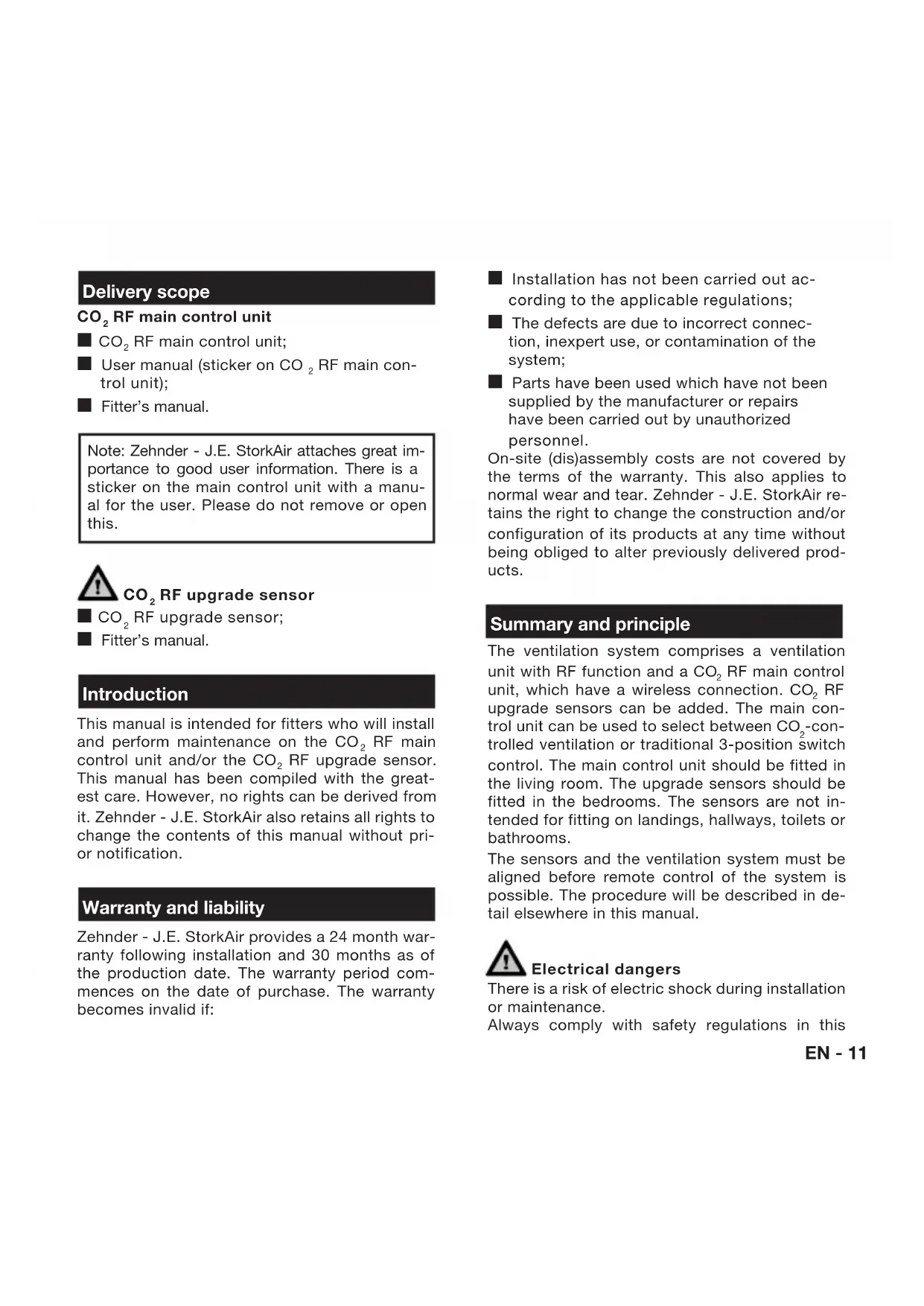
Leveringsomvang
CO2RF main control unit
CO2RF main control unit;
■ User manual (sticker on CO₂ RF main control unit);
Fitter's manual.
Note: Zehnder - J.E. StorkAir attaches great importance to good user information. There is a sticker on the main control unit with a manual for the user. Please do not remove or open this.

CO_2 RF upgrade sensor
CO2RF upgrade sensor;
Fitter's manual.
Introduction
This manual is intended for fitters who will install and perform maintenance on the CO2 RF main control unit and/or the CO2 RF upgrade sensor. This manual has been compiled with the greatest care. However, no rights can be derived from it. Zehnder - J.E. StorkAir also retains all rights to change the contents of this manual without prior notification.
Warranty and liability
Zehnder - J.E. StorkAir provides a 24 month warranty following installation and 30 months as of the production date. The warranty period commences on the date of purchase. The warranty becomes invalid if:
■ Installation has not been carried out according to the applicable regulations;
The defects are due to incorrect connection, inexpert use, or contamination of the system;
Parts have been used which have not been supplied by the manufacturer or repairs have been carried out by unauthorized personnel.
On-site (dis)assembly costs are not covered by the terms of the warranty. This also applies to normal wear and tear. Zehnder - J.E. StorkAir retains the right to change the construction and/or configuration of its products at any time without being obliged to alter previously delivered products.
Summary and principle
The ventilation system comprises a ventilation unit with RF function and a CO2 RF main control unit, which have a wireless connection. CO2 RF upgrade sensors can be added. The main control unit can be used to select between CO_2 -controlled ventilation or traditional 3-position switch control. The main control unit should be fitted in the living room. The upgrade sensors should be fitted in the bedrooms. The sensors are not intended for fitting on landings, hallways, toilets or bathrooms.
The sensors and the ventilation system must be aligned before remote control of the system is possible. The procedure will be described in detail elsewhere in this manual.

Electrical dangers
There is a risk of electric shock during installation or maintenance.
Always comply with safety regulations in this
manual. If the safety regulations, warnings, comments and instructions are not complied with, this can lead to personal injury or damage to the product.
Disconnect the electrical group to which the main control unit or upgrade sensor is connected, before opening the cover of the device.

Electrostatic discharge (ESD)
There is a risk that PCBs may be damaged by an electrostatic discharge if electrical components have to be exchanged. For this reason, always take ESD-inhibiting measures when dealing with PCBs, such as wearing an antistatic wristband.

Do not use the CO_2 sensor for safety-related control of the gas supply, as it is intended only for use in living areas.

The CO_2 sensor can be disrupted by other RF transmitters.
Installation
Installation
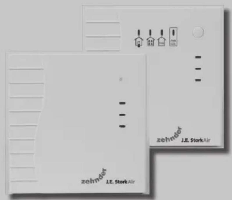
The CO2 RF main control unit and the CO2 RF upgrade sensor are constructed from a sensor section (the front) and a transmitter section (the rear).

B
A
The transmitter section has been designed for mounting on a flush socket. The sensor section must be separated from the transmitter section in order to mount the devices on the wall and to electrically connect them. To do so, use a small screwdriver to press the 2 click fingers (B) in the air channels on the top of the device down
wards slightly and pull the sensor section upwards.

Note: When putting back the sensor, the 4 pins (A) of the electrical connect fall into the contacts of the transmitter. Ensure that the regulator is put back in a that allows the air to move freely through channels. When selecting the position, there are no large metal obstacles between ventilation unit and the CO2 sensor. Diant heat or warm supply air must also be The recommended position for the CO2
RF main control unit is next to the thermostat or light switch in the living room. The upgrade sensors should be fitted in the bedrooms.
Electrical connections
The CO2 sensors must be connected in conformance with locally prevailing procedures. The CO2 sensor transmitter section is connected to the 230V / 50Hz grid via a flush socket. Push the cables through the rear of the casing. Securely screw the transmitter section to the flush socket.

Connection between the ventilation unit and the CO_2 sensors
The following steps must be carried out to make a connection between the ventilation unit and the CO_2 sensors:
Ventilation unit
Ensure that the RF input of the ventilation unit is set to "proportional control". Consult the fitter's manual for the ventilation unit for more information.
- Remove the ventilation unit plug from the socket and replace after 5 seconds. The device is now in programming mode. A connection can be made with the main control unit within 10 minutes.
CO, RF main control unit
- Press the button on the CO_2 RF main control unit for approximately 8 seconds. The sensor will now establish a connection with the ventilation unit. The green, orange and red LEDs flash to confirm that the communication has been established.
CO, RF upgrade sensor
- Repeat step 1. Use a pointed object (paperclip or pen) to press the button on the upgrade sensor until the green, orange and red LEDs flash (approximately 8 seconds).
- Repeat step 3 until all upgrade sensors are connected.
Connection problems
The following problems may occur when connecting the sensors or accessories:
The red LED on the CO2 RF main control unit flashes. No connection has been established with the ventilation unit. Repeat step 1 and 2. If this is ineffective, check that the distance between the ventilation unit and the sensor is not too large and that the communication is not impeded by large metal obstacles;
The red LED on the CO2 RF upgrade sensor flashes. No connection has been established between the CO2 RF upgrade sensor and the ventilation unit, or the CO2 RF main control unit is not connected. Check that the CO_2 RF main control unit is working properly. Then repeat step 3.
Operation
Users can select one of 4 ventilation settings using the button on the main control unit: absent, present, maximum or "Auto CO2 ". The setting selected is indicated by a blue LED. The ventilation is automatically controlled in the "Auto CO2 " setting based on the CO2 concentration. When only the main control unit is used, this relates exclusively to the CO2 levels in the living room. If the upgrade sensors are also used, then this highest CO2 concentration is normative for the ventilation volume. The upgrade sensor does not function as a control unit and is only intended to monitor CO2 levels in a living area. There are 3 LED indicators on the sensors which display the CO_2 levels:
Green (<1200ppm);
Orange (1200 - 1500ppm);
Red (>1500ppm)
Residents are advised to open a door or window if the red LED lights up. Furthermore all gaps under doors - which are essential for effective ventilation - as well as the position of window gratings (if fitted) must be checked.
Malfunction
The following malfunctions can occur:
The green, orange and red LEDs flash. The 3-position switch on the main control unit still works. The CO2 sensor is defective or seriously contaminated. Clean the CO2 sensor or replace it;
The red LED flashes, while the green or orange LED is constantly illuminated. The sensor cannot establish a connection with the ventilation unit. Check the distance and for the presence of any large metal obstacles between sensor and ventilation unit.
Maintenance
The CO_2 sensors are maintenance-free throughout the entire lifespan. The operation can be interrupted by contamination of the air channels. Remove the dust from the casing and from the air channels where required.
Specifications
CO2 RF main control unit and CO2 RF upgrade sensor
Power supply: 230V ± 10% , single-phase, 50Hz;
Minimum ambient temperature: -10^
Maximum ambient temperature: +40^
Humidity (continued): 85% (electronics), non-condensing;
Functional measurement range 400ppm - 2000ppm;
Sensor malfunction if measurement value is < 300ppm or >10000ppm ;
Target value 1050ppm;
Output signal 0% RF - 100% RF ,proportional; integrating subject to target value deviation;
Unit consumption: typically < 1W
Degree of pollution: 2;
Peak voltage: 4kV
Protection class: II in compliance with EN60730-1;
IP classification: IP30 in compliance with EN60529-1;
Type of regulator: RS type 1.
Lieferumfang

- Leveringsomvang
- CO2RF main control unit
- Introduction
- Warranty and liability
- Summary and principle
- Electrical dangers
- Electrostatic discharge (ESD)
- Installation
- Electrical connections
- Connection between the ventilation unit and the CO_2 sensors
- Ventilation unit
- CO, RF main control unit
- CO, RF upgrade sensor
- Connection problems
- Operation
- Malfunction
- Maintenance
- Specifications
- Lieferumfang
Brand : ZEHNDER
Model : CO2 RF
Category : Thermostat