
ComfoControl Luxe - Thermostat ZEHNDER - Free user manual and instructions
Find the device manual for free ComfoControl Luxe ZEHNDER in PDF.
| Product type | Control panel for ventilation and cooling system |
| Brand | Zehnder |
| Model | ComfoControl Luxe |
| Category | Thermostat / Ventilation controller |
| Power supply | 12 V DC from ventilation system |
| Communication | RS485 via A/B cable (shielded twisted pair 4x0.25 mm²) |
| Display type | Touch |
| Mounting | Wall-mounted, 1.50 m above floor |
| Internal temperature sensor | Yes |
| External temperature sensor | Optional (NTC 10 kΩ) |
| Ventilation settings | 4 positions: Away, Low, Normal, High (with possible timed override) |
| Schedule programming | Daily ventilation and temperature schedule, copy possible |
| Functions | Comfort temperature setting, temperature offset, programming, time delays, fault display, filter warning, hood and fan control |
| Languages | Multiple, adjustable via menu |
| Maintenance | Replace filters according to displayed warning |
| Safety | Do not install near heat or cold sources; follow installation instructions |
| Warranty | 24 months after installation, max 30 months after manufacture |
| Additional information | Manual available in multiple languages (FR, DE, EN, NL, etc.) |
Frequently Asked Questions - ComfoControl Luxe ZEHNDER
User questions about ComfoControl Luxe ZEHNDER
0 question about this device. Answer the ones you know or ask your own.
Ask a new question about this device
Download the instructions for your Thermostat in PDF format for free! Find your manual ComfoControl Luxe - ZEHNDER and take your electronic device back in hand. On this page are published all the documents necessary for the use of your device. ComfoControl Luxe by ZEHNDER.
USER MANUAL ComfoControl Luxe ZEHNDER
Installingen make in P-menu's
All rights reserved.
This manual has been compiled with the utmost care. The publisher cannot be held liable for any damage caused as a result of missing or incorrect information in this manual.
Table of Contents
1 INTRODUCTION 1
1.1 Foreword 1
1.2 Warranty and liability 1
1.2.1 General 1
1.2.2 Warranty conditions 1
1.2.3 Liability 1
1.3 Safety instructions 1
1.3.1 Pictograms used 1
2 FOR THE USER 1
2.1 ComfoControl 2
2.2 Using ComfoControl 2
2.2.1 Time and date settings 2
2.2.2 Comfort temperature settings 3
2.2.3 Ventilation volume settings 3
2.2.4 Switching extractor hood on/off 4
2.2.5 Switching supply and exhaust fan on/off 4
2.2.6 Ventilation programme settings 5
2.2.7 Temperature programme settings 6
2.2.8 Time delay settings 7
2.2.9 Temperature correction settings 7
2.2.10 Screen settings 8
2.2.11 Language settings 8
2.3 System data 9
2.3.1 ComfoControl error messages 9
2.3.2 ComfoControl filter warning 9
2.3.3 Information about ComfoControl status 9
2.4 End of useful life 10
3 FOR THE FITTER 10
3.1 Installation conditions 10
3.2 Installing ComfoControl 10
3.2.1 Transport and unpacking 10
3.2.2 Checking the delivery 10
3.3 Wall mounting 10
3.4 Connection to ventilation system 10
3.5 Connection to external temperature sensor 11
3.6 Commissioning ventilation and cooling system 11
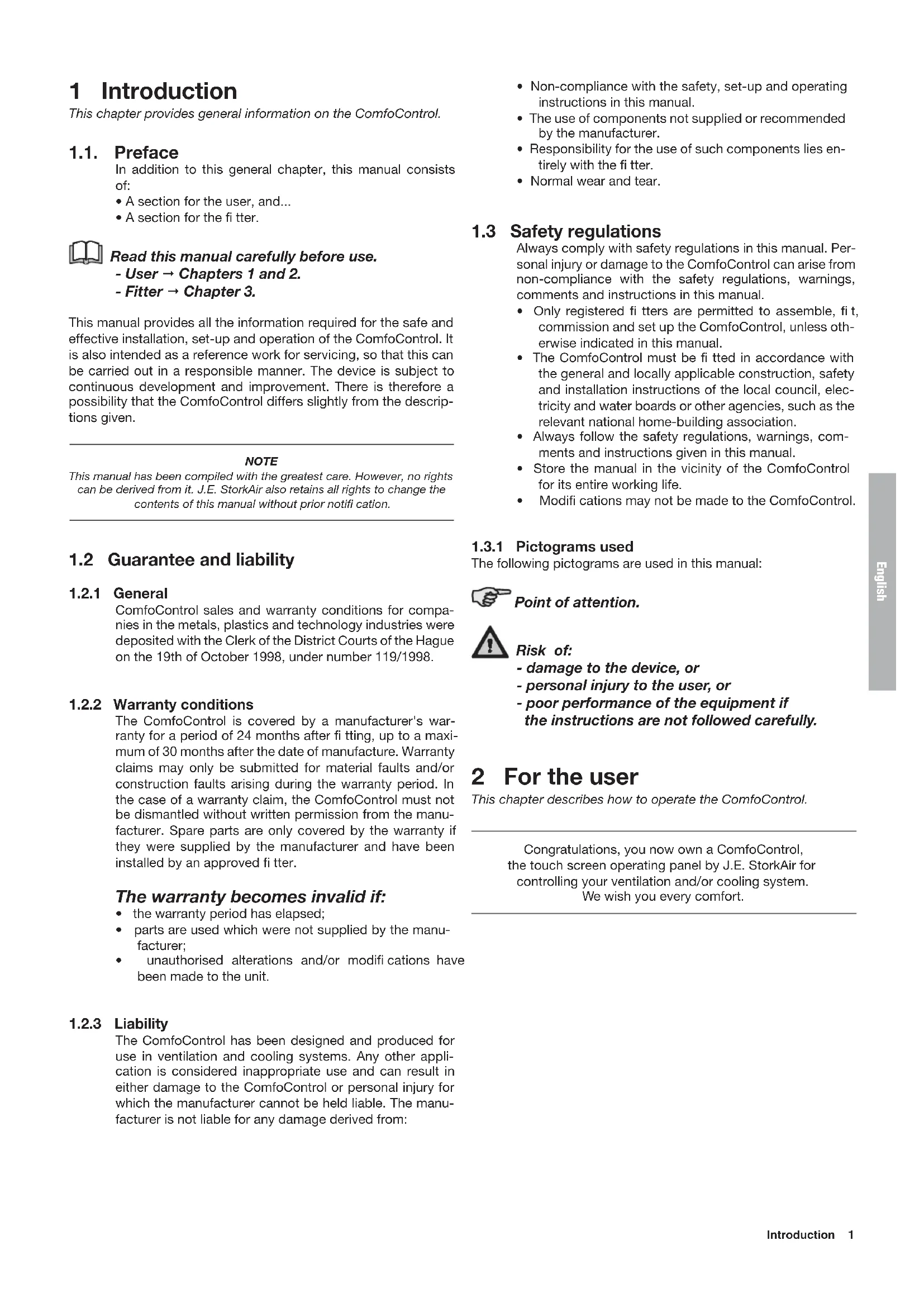
1 Introduction
This chapter provides general information on the ComfoControl.
1.1. Preface
In addition to this general chapter, this manual consists of:
- A section for the user, and...
A section for the fitter.

Read this manual carefully before use.
-User → Chapters 1 and 2.
-Fitter → Chapter 3.
This manual provides all the information required for the safe and effective installation, set-up and operation of the ComfoControl. It is also intended as a reference work for servicing, so that this can be carried out in a responsible manner. The device is subject to continuous development and improvement. There is therefore a possibility that the ComfoControl differs slightly from the descriptions given.
NOTE
This manual has been compiled with the greatest care. However, no rights can be derived from it. J.E. StorkAir also retains all rights to change the contents of this manual without prior notification.
1.2 Guarantee and liability
1.2.1 General
ComfoControl sales and warranty conditions for companies in the metals, plastics and technology industries were deposited with the Clerk of the District Courts of the Hague on the 19th of October 1998, under number 119/1998.
1.2.2 Warranty conditions
The ComfoControl is covered by a manufacturer's warranty for a period of 24 months after fitting, up to a maximum of 30 months after the date of manufacture. Warranty claims may only be submitted for material faults and/or construction faults arising during the warranty period. In the case of a warranty claim, the ComfoControl must not be dismantled without written permission from the manufacturer. Spare parts are only covered by the warranty if they were supplied by the manufacturer and have been installed by an approved fitter.
The warranty becomes invalid if:
the warranty period has elapsed;
- parts are used which were not supplied by the manufacturer;
- unauthorised alterations and/or modifi cations have been made to the unit.
1.2.3 Liability
The ComfoControl has been designed and produced for use in ventilation and cooling systems. Any other application is considered inappropriate use and can result in either damage to the ComfoControl or personal injury for which the manufacturer cannot be held liable. The manufacturer is not liable for any damage derived from:
- Non-compliance with the safety, set-up and operating instructions in this manual.
- The use of components not supplied or recommended by the manufacturer.
- Responsibility for the use of such components lies entirely with the fi tter.
Normal wear and tear.
1.3 Safety regulations
Always comply with safety regulations in this manual. Personal injury or damage to the ComfoControl can arise from non-compliance with the safety regulations, warnings, comments and instructions in this manual.
- Only registered fi tters are permitted to assemble, fi t, commission and set up the ComfoControl, unless otherwise indicated in this manual.
- The ComfoControl must be fitted in accordance with the general and locally applicable construction, safety and installation instructions of the local council, electricity and water boards or other agencies, such as the relevant national home-building association.
- Always follow the safety regulations, warnings, comments and instructions given in this manual.
- Store the manual in the vicinity of the ComfoControl for its entire working life.
- Modifi cations may not be made to the ComfoControl.
1.3.1 Pictograms used
The following pictograms are used in this manual:

Point of attention.

Risk of:
-damage to the device, or
- personal injury to the user, or
- poor performance of the equipment if the instructions are not followed carefully.
2 For the user
This chapter describes how to operate the ComfoControl.
Congratulations, you now own a ComfoControl, the touch screen operating panel by J.E. StorkAir for controlling your ventilation and/or cooling system. We wish you every comfort.
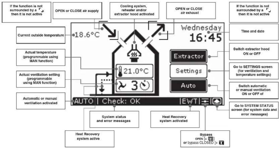
2.1 ComfoControl
The ComfoControl regulates your ventilation and/or cooling system.
The ComfoControl is mounted to the living room wall and communicates with your ventilation and/or cooling system.
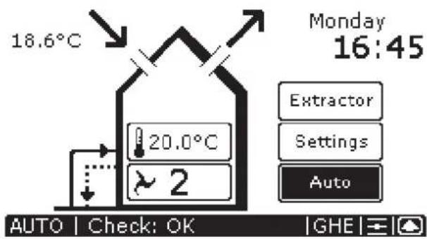
The list below briefly explains what information the unit displays.
The ComfoControl display is a touch screen. All settings can be accessed, adjusted and confirmed simply by touching the screen.
2.2 Using ComfoControl
The ComfoControl is used for the following:
- Setting time and date.
- Setting the comfort temperature.
- Setting the ventilation volume.
- Switching the extractor hood on/off.
- Switching the supply and exhaust fan on/off.

If your ventilation system has a chimney cleaning function, you will be unable to switch the supply and exhaust fan on and off.
- Setting a personal ventilation programme.
- Setting a personal temperature programme.
- Setting a time delay for a number of ventilation settings.
- Setting a temperature correction.
- Setting the screen.
- Setting the language.
A concise explanation of the above listing is given in the paragraphs below.
2.2.1 Time and date settings
Use the ComfoControl to:
- Set the date and time.
The procedure is as follows:
- Press "DAY AND TIME", here " Monday 00:00".
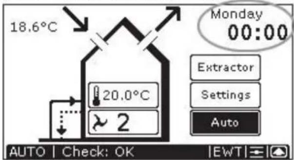
- Press "or" to set the day.
- Pressleft " " or "to set the hour.
- Pressright " or " to set the minutes.
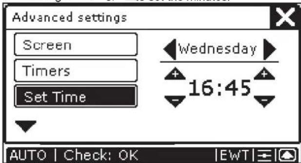
- Press "X" to confirm the settings and return to the main screen.

After 30 seconds, the ComfoControl will return to the main menu automatically. Your settings have now been saved.
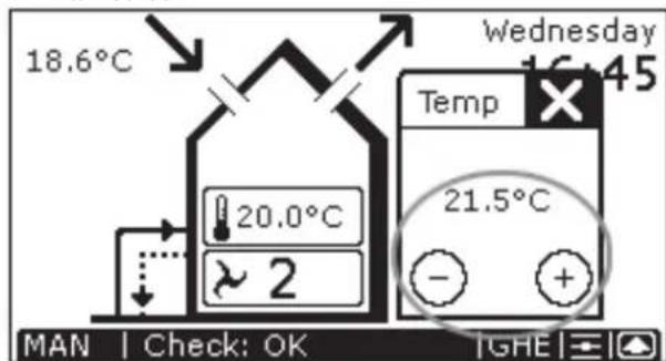
2.2.2 Comfort temperature settings
The procedure is as follows:
- Press "COMFORT TEMPERATURE", currently
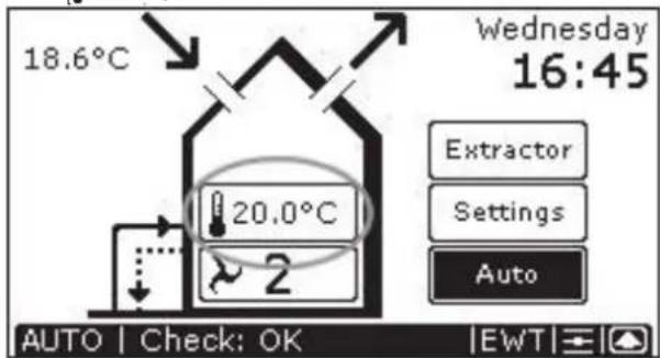
- Press "or" set the comfort temperature.
- Press "No confirm the settings and return to the main screen.
Comfo unit
The comfort temperature. Your Comfortunit-equipped ventilation system tries continuously to maintain the temperature of the room in which the operating panel is located at the set comfort temperature.
It may have to open the bypass or activate the active cooling to realize this objective.
- The comfort temperature can be set to between COOL and WARM. Between these two parameters, you can set it to 18 - 24ircC .
- When COOL is selected, the system attempts to keep the temperature as low as possible. If conditions allow, active cooling will be activated. Use this setting if you wish to cool the dwelling considerably.
- If WARM is selected, then the active cooling will never be activated and the bypass remains closed. Use this setting when you turn the heating up.
- Your heat-recovery unit is fitted with a system that detects whether it is summer or winter. In the summer, the active cooling can be activated, while this is not desirable under normal winter conditions. All the same, if you wish to use active cooling in the winter, then set the temperature to COOL.
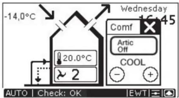
Active cooling can be deactivated. In the screen in which the comfort temperature can be entered, you will see a button that can be set to either "Artic Auto" or "Artic Off". Select "Artic Off" if you do not wish to use active cooling, even if your dwelling gets warmer than the required comfort temperature.

After 30 seconds, the ComfoControl will return to the main menu automatically. Your settings have now been saved.
2.2.3 Ventilation volume settings
The procedure is as follows:
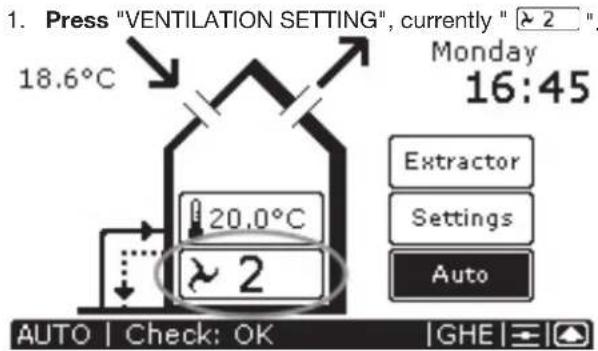
- Press "or" to set the ventilation volume.
- Press "Xo confirm the settings and return to the main screen.

After 30 seconds, the ComfoControl will return to the main menu automatically. Your settings have now been saved.
There are 4 ventilation volumes/settings. These are:
Setting → Absent.
- Use when absent.
Setting 1 → Low setting
- Use for low ventilation levels.
Setting 2 "→Normal.
- Use for normal
ventilation levels.
Setting [3]3→ High setting.
- Use for cooking, showering and if extra ventilation is required.
Setting "3" → High setting, with programmed deactivation delay. See §2.2.8.
- Use for cooking, showering and if extra ventilation is required.
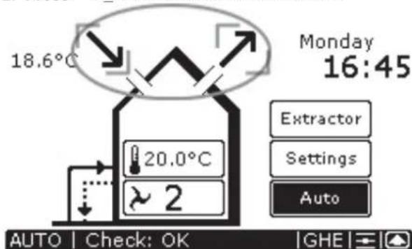
The ComfoControl will display "AUTOC standards during manual ventilation, and not "MHN
If you wish to reactivate the automatic ventilation setting, then:
- Press "AUTO" to return to the automatic ventilation setting.
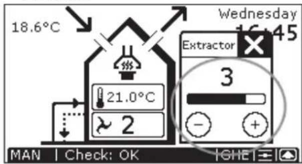
2.2.4 Switching extractor hood on/off
The procedure is as follows:
- Press " Extractor" to activate the extractor hood.
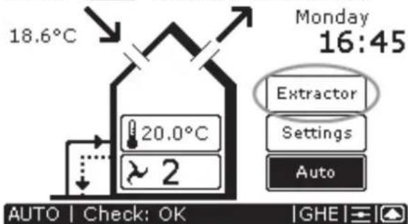
- Press "O" or "O" to set the ventilation volume for the extractor hood.
- Press "X" to confirm the settings and return to the main screen.
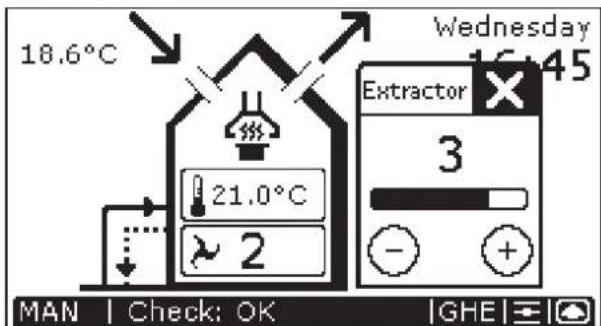

The extractor hood symbol (1) then appears on the ComfoControl display.
- Press "Extract" to deactivate the extractor hood.
Note!
If the extractor hood is fitted with a time-delay switch (see § 2.2.8 for more information about time delay), then it will not switch off immediately, but will continue to run for the programmed time period.

The extractor hood symbol ("disappears from the ComfoControl display once the programmed time delay has run its course.
Note!
If the extractor hood is fitted with a time-delay switch (see § 2.2.8 for more information about time delay), then the time delay symbol (空) will appear on the ComfoControl display in place of the ventilation volume buttons. The extractor hood will be switched off after the programmed number of minutes.
There is no ventilation volume setting ("") displayed on the ComfoControl is when the extractor hood is activated. Instead, the extractor hood ventilation setting is displayed in the extractor hood symbol. These are:
for extractor hood ventilation setting 1.
for extractor hood ventilation setting 2.
for extractor hood ventilation setting 3.
If the extractor hood is running, the programmed ventilation setting is displayed in the extractor hood symbol (e.g. "").
2.2.5 Switching the supply and exhaust fan on/off
The procedure is as follows:
- Press " to switch off the supply fan.
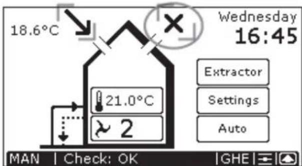
- Press " to switch off the exhaust fan.

Once the supply and exhaust fans have been deactivated, "X" is displayed on the ComfoControl to indicate they are switched off.
- Press "X" by the supply fan symbol to reactivate the supply fan.
- Press "X" by the exhaust fan symbol to reactivate the exhaust fan.
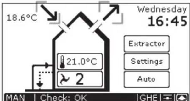

Once the supply and exhaust fans have been activated, both "√" and "↑" are displayed on the ComfoControl to indicate they have been switched on again.

Bear in mind that switching off the supply or exhaust fan will temporarily immobilize your balanced ventilation system.

Once the supply or exhaust fan has been deactivated, "AUTO" will no longer be displayed, but "MAN" appear on the ComfoControl as standard.

If your ventilation system has a chimney cleaning function, you will be unable to switch the supply and exhaust fan on and off.
2.2.6 Setting the ventilation programme
The ventilation volume can be changed/set as follows:
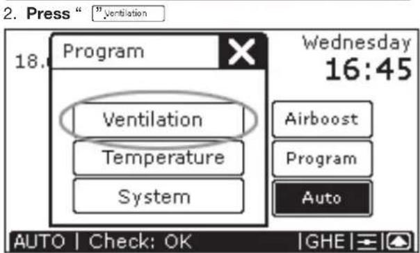
- Setting the ventilation programme.
Select day: "Mo", "Tu", "We", "Th", "Fr", "Sa" or "Su".
Select hour, 00:00 to 23:00, using or
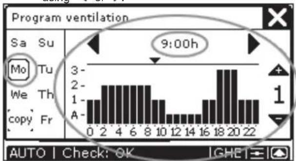
If required, press the hour, for example: “”, and then select the minutes using “” or “▼, for example: “9:30h”.
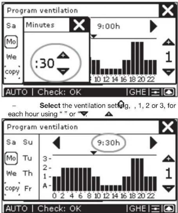
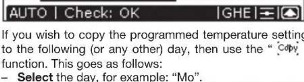
If you wish to copy the programmed ventilation setting to the following (or any other) day, then use the "Copy" function. This goes as follows:
- Select the day, for example: "Mo".
- Press "Copy", which changes to "Copy".
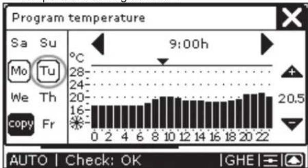
- Select the day to which the ventilation setting is to be copied, for example: "Tu". "Tu" now has the same ventilation setting as "Mo".
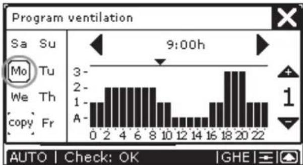
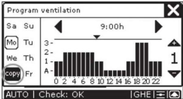
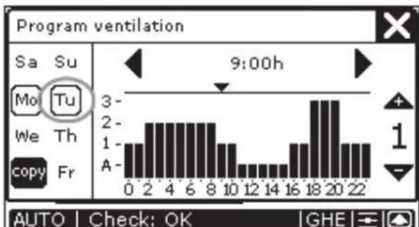
- Press "X" to confirm the settings and return to the
main screen.

The programmed ventilation level only works in the AUTO setting.

After 30 seconds, the ComfoControl will return to the main menu automatically. Your settings have now been saved.
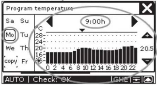
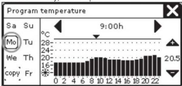
2.2.7 Temperature programme settings
Use the ComfoControl to:
- Set a personal temperature programme.
The ComfoControl comes with default temperature settings. If so required, you can change the standard temperature programme to meet your personal temperature requirements. Examples include weekday and weekend programmes. The temperature settings can be changed/ set as follows:
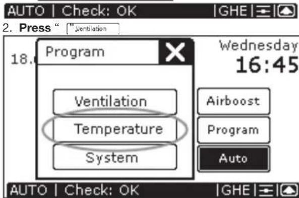
3. Setting the temperature programme.
- Select day: "Mo", "Tu", "We", "Th", "Fr", "Sa" or "Su".
- Select hour, 00:00 to 23:00, using “<” or “>”.
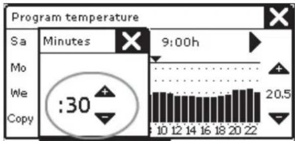
If required, press the hour, for example: "9:00h", and then select the minutes using "▼" or "▲", for example: "9:30h - Select the temperature setting (12 to 28 °C) for each hour using “or ”.
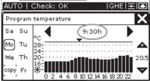
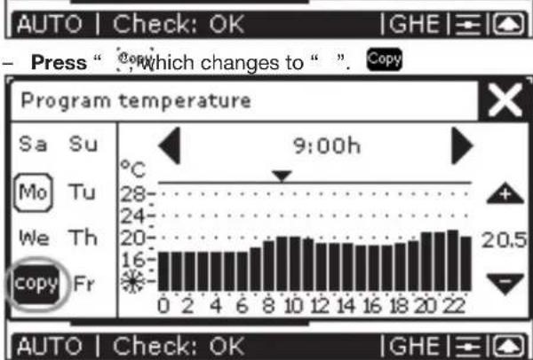
- Select the day to which the temperature setting is to be copied, for example: "Tu". "Tu" now has the same temperature setting as "Mo".
- Press "X" to confirm the settings and return to the main screen.

The programmed temperature level only works in the AUTO setting.

After 30 seconds, the ComfoControl will return to the main menu automatically. Your settings have now been saved.
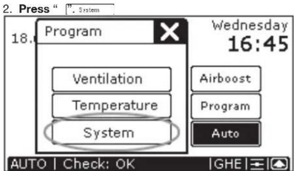
2.2.8 Time delay settings
Use the ComfoControl to:
Programme a time delay for certain ventilation settings.
The procedure is as follows:
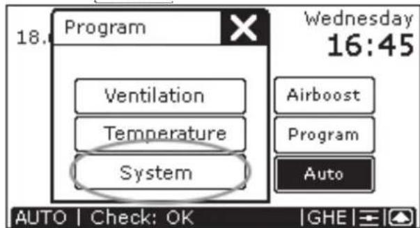
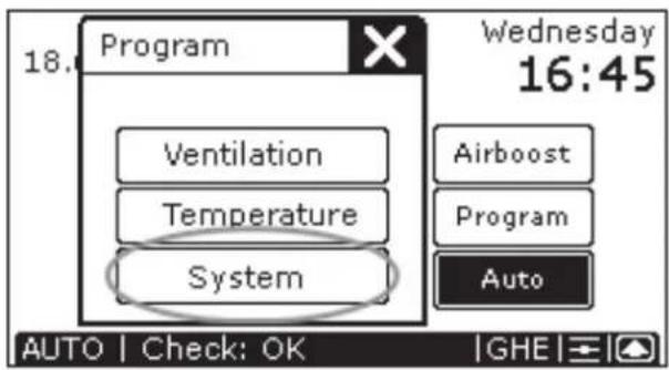
- Press "System
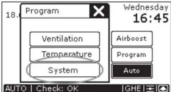
- Press "Tmers
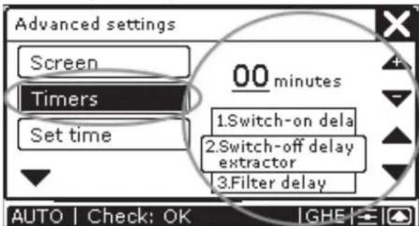
- Press " " or " " to choose between:
Time delay for the bathroom off switch
→ Maximum 120 minutes.
Time delay for the extractor hood off switch
→ Maximum 180 minutes.
Delay the "FILTER DIRTY" message on the
ComfoControl → Maximum 26 weeks.
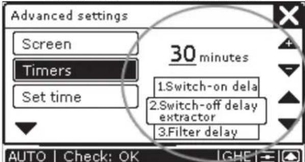
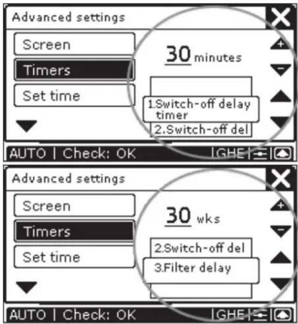
- Press "▼" or "▲" to set the number of minutes (weeks) delay required.
- Press "X" to confirm the settings and return to the main screen.

The minimum and maximum time delay for the (ventilation) settings are preset in the software.

After 30 seconds, the ComfoControl will return to the main menu automatically. Your settings have now been saved.
2.2.9 Temperature correction settings
If the ComfoControl is used in conjunction with a heating system thermostat, we recommended synchronizing the temperature for both units on the display.
Use the ComfoControl to:
- Programme a temperature correction relative to the recorded temperature.
The procedure is as follows:
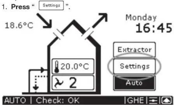
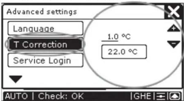
3. Press "and then " .T Correction
- Press "or" to correct the irc C setting.
- Press "X" to confirm the settings and return to the main screen.

After 30 seconds, the ComfoControl will return to the main menu automatically.
2.2.10 Screen settings
Use the ComfoControl to:
- Set the clarity and contrast of the touch screen.
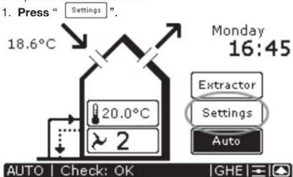
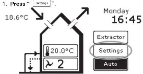
The procedure is as follows:
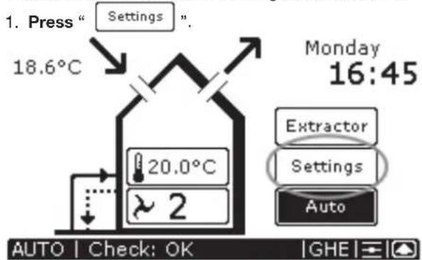
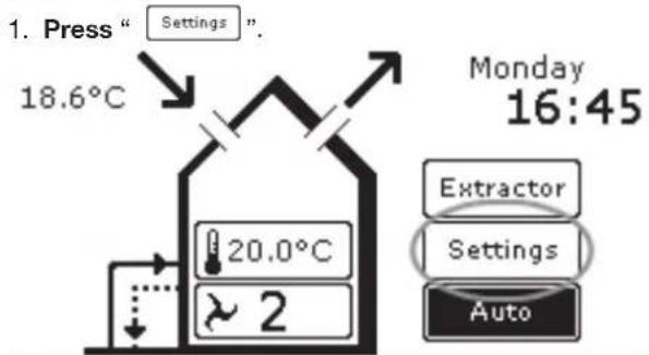
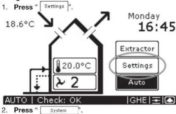
- Press "Settings".
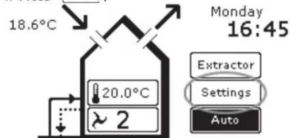
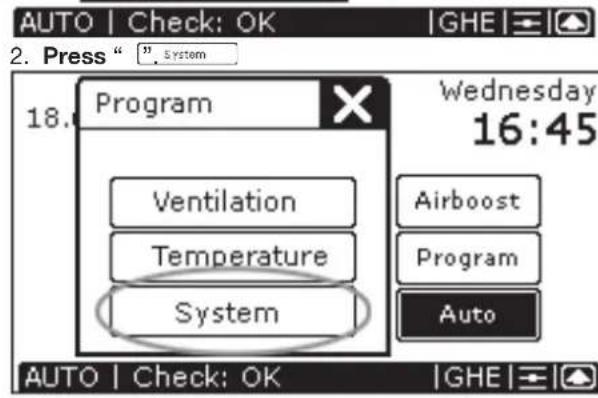
AUTO Check: OK GHE 2. Press " System
- For "BRIGHTNESS" press "O" or "O" to adjust the clarity.
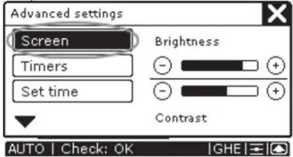
- For "CONTRAST", press "or " to adjust the contrast.
- Press "X" to confirm the settings and return to the main screen.

After 30 seconds, the ComfoControl will return to the main menu automatically. Your settings have now been saved.
2.2.11 Language settings
Use the ComfoControl to:
- Select a language.
The procedure is as follows:
- Press " 4. Press " or " " to select the required language.
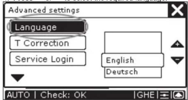
- Press "X" to confirm the settings and return to the main screen.

After 30 seconds, the ComfoControl will return to the main menu automatically. Your settings have now been saved.
2.3 System data
Certain system information can be displayed on the ComfoControl:
- Error messages.
- Warning to clean or replace the filters.
Information on the status of your ventilation and/or cooling system.
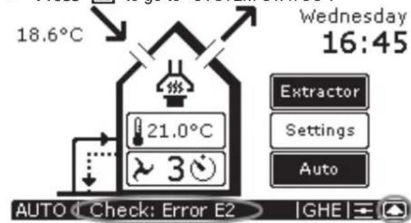
2.3.1 ComfoControl error messages
In the event of a malfunction, the ComfoControl will display the corresponding code.
The ComfoControl display will show an 'A' or an 'E', followed by a number.
What to do in the event of a malfunction
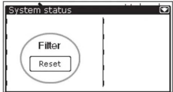
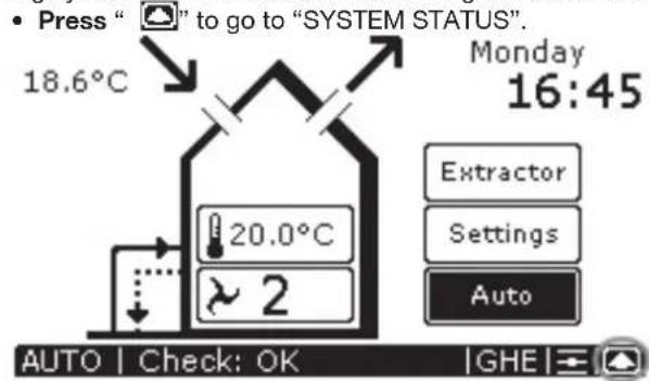
In the event of a malfunction, reset as follows: Press "O" to go to "SYSTEM STATUS".
- Press "Reset" to delete the error message, for example "ERROR E2".
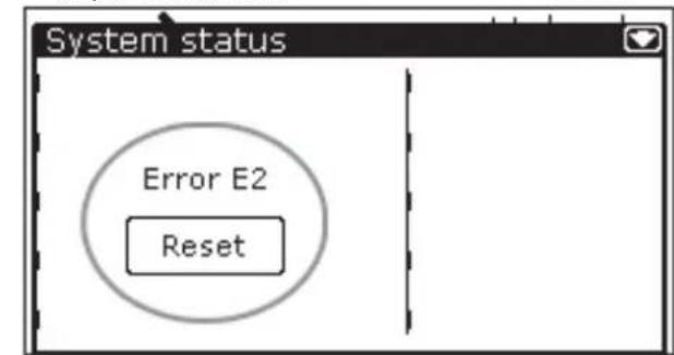

Multiple malfunctions will be displayed as a list.

Multiple malfunctions will be displayed in the "SYSTEM STATUS" screen. only "ERROR E2" is currently displayed.
If the same malfunction returns repeatedly, please contact the fitter.
Make a note of which ventilation and/or cooling system you have.
Make a noteof the error code on the ComfoControl display.
The system should not be unplugged, unless your ventilation and/or cooling system must be taken out of service due to a serious malfunction, or for filter cleaning/replacement or any other compelling reasons. When the unit is unplugged, the dwelling will no longer enjoy mechanical ventilation, and this can lead to problems with damp and mould. For this reason, please avoid switching off your
ventilation and/or cooling system for long periods.
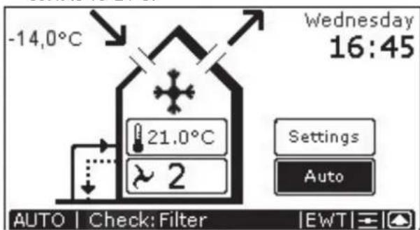
2.3.2 ComfoControl fi Iter warning
If the ventilation system's fi iters require replacement (or cleaning), then the "FILTERS - REPLACE FILTERS" warning appears on the ComfoControl display.

To replace (or clean) any fi iters, please refer to your ventilation system's user manual.
Once the ventilation system's fi iters have been replaced (or cleaned), then follow the steps below to delete the fi Iter warning from the ComfoControl display:
- Press "Reset" to delete the "FILTERS- REPLACE FILTERS" warning.
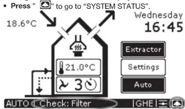
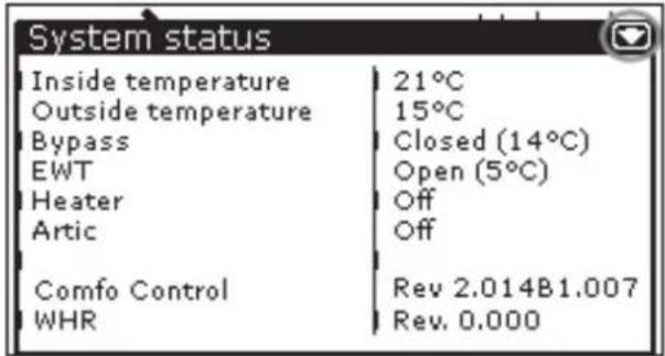
2.3.3 Information about ComfoControl status
In the absence of error message, you will see:
- "CHECK: OK" on the ComfoControl display.
Information on the status of your ventilation and/or cooling system can then be accessed. This goes as follows:
The "SYSTEM STATUS" screen displays all the system data on the ComfoControl.
- Press " return to the main screen.
2.4 End of useful life
Consult your supplier as to what you should do with the ComfoControl at the end of its useful life. If the ComfoControl cannot be returned to the supplier, avoid disposing of it with the industrial waste, and ask your local council about the options for recycling the components or processing the materials in an environmentally friendly manner.
3 For the Fitter
This chapter describes how to fit the ComfoControl.
3.1 Installation conditions
In order to determine whether the ComfoControl can be installed in a certain area, the following aspects must be taken into account:
- The ComfoControl must be mounted 1.5 metres from the floor.
- The ComfoControl must be fitted to allow sufficient air to circulate. For example, not behind a cupboard, or in a corner.
- The ComfoControl must not be located close to a heat source, such as radiators, TVs, lamps, etc. Direct sunlight must also be avoided.
- The ComfoControl must not be located close to a cold source, such as cold-water pipes or unheated walls (due to poorly heated areas on the other side of the wall), etc.
- The following facilities must be available in the living area concerned:
Flush-fit casing for the ComfoControl.
12V DC power supply from the ventilation system.
A/B communication cable from the ventilation system.
3.2. Installing ComfoControl
3.2.1 Transport and unpacking
Take care when transporting and unpacking the ComfoControl.

Make sure the packing material is disposed of in an environmentally friendly manner.
3.2.2 Checking the delivery
Contact your supplier immediately in case of damage or an incomplete delivery. The delivery includes:
ComfoControl.
- Mounting bracket (fi tted to the bottom of the ComfoControl).
- Connectors (fi tted to the rear of the ComfoControl on the PCB).
- User manual.
3.3 Wall mounting
- Mount the bracket on the wall.
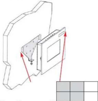

The bracket has five mounting holes.

If required, the bracket can be fitted to the fl ushfi t casing.
- Connect the ComfoControl to the ventilation system; see § 3.4.
- Slide the ComfoControl onto the mounting bracket.
- Fasten the bottom of the ComfoControl with a screw.
3.4 Connection to ventilation system
- Connect the 12V DC cable to the connector.
- Connect the A/B communication cable to the connector.
The wiring diagram can be found at the rear of the ComfoControl:
- Plug the connector into the 12V DC "POWER" fitting on the PCB.
- Plug the connector into the RS 485 "COMM" fitting on the PCB.
| Open Co | mm Power Relay | Relay Temp.Sens | |||||||
| Therm RS | 485 12V DC | 1 | 2 | ||||||
| * | * | A | B | - | + | * | * | * | * |

The cable specifi cation is: 4× 0.25mm protected (twisted pair).
3.5 Connection to external temperature sensor
- Connect the temperature sensor cable to the connector.
The wiring diagram can be found at the rear of the ComfoControl:
- Plug the connector into the "TEMP.SENS" fitting on the PCB.
- Fit both jumpers to the PCB at position 1:2 (left).
| Jumper Left: Temp. Senso Jumper Right: Relay 2 | |||||||||
| Open Co | mm Power Relay | Relay | Temp. Sens | ||||||
| Therm RS | 485 12V DC | 1 | 2 | ||||||
| * | * | A | B | - | + | * | * | - | + |

The temperature sensor specifi cation is: NTC 10 KΩ (optional).
The external temperature sensor is optional. The indoor temperature is usually monitored by an internal temperature sensor (in the ComfoControl). However, indoor temperature can also be monitored using an external temperature sensor. This may be because the ComfoControl is to be fitted in a different location than the one to be monitored, for example in the hall. It is also possible that variables in the vicinity of the unit (e.g. wall temperature) could affect temperature readings. An external temperature sensor connected to the PCB in the back of the ComfoControl provides a solution to these problems.
3.6 Commissioning the ventilation and cooling system
Once fitted, the ventilation and cooling system must be commissioned.
This can be done via the P menus of the ComfoControl. These P menus can be used to enter various settings (and programmes) for the ventilation and cooling system. An overview of the available P menus is given below:

For a list of available settings in the P (sub)menu, please refer to the user manual for your ventilation and/or cooling system.
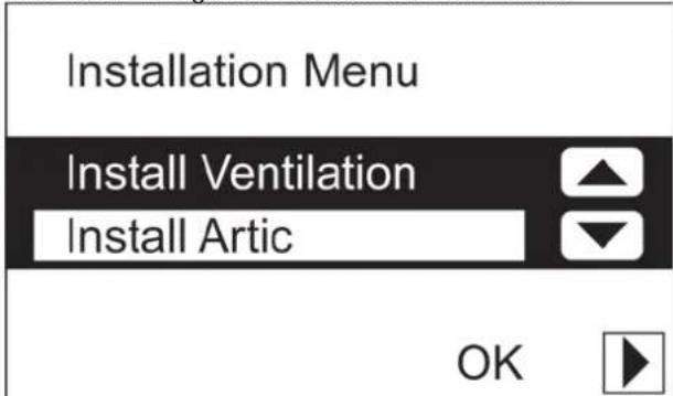
Accessing P menus
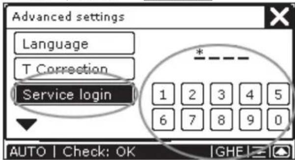
3. Press "and then Service login
4. Press code "3520" to go to the "INSTALLATION MENU".
-
Press "or" to go to:
-
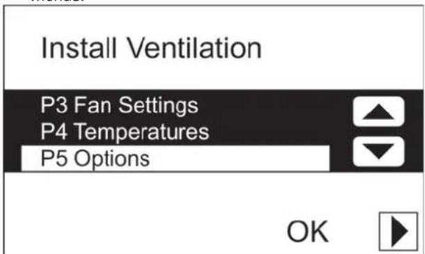
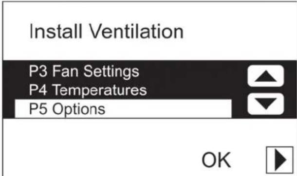
The "INSTALL VENTILATION" menu, or ...
- The "INSTALL ARTIC" menu.
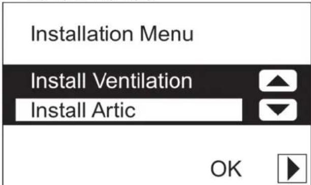
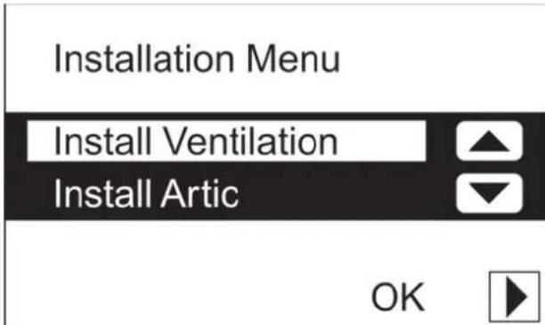
6. Press "OK" to enter the selected menu.

The P menus are now accessible

If the Artic cooling system is not connected, the "OK" will not appear on the screen, and the related P menus will not be available.
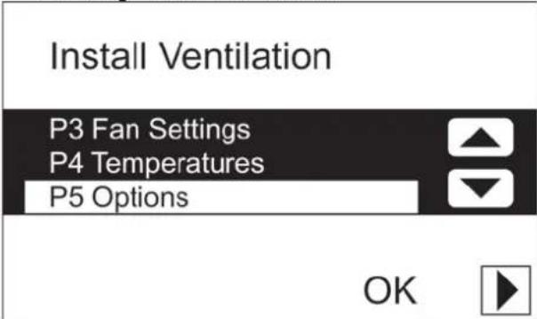
- Using "or", select the required P menu, e.g. "P5 OPTIONS".
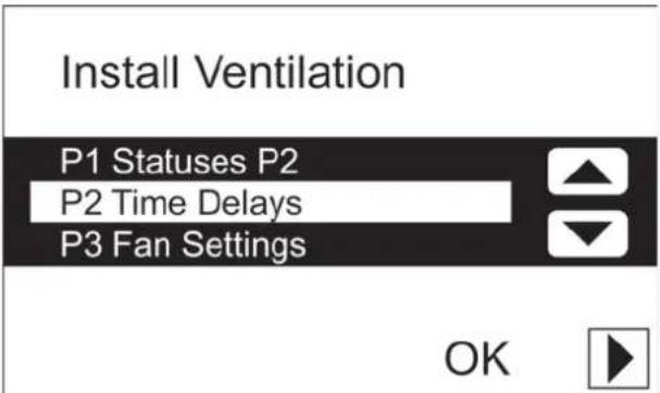
- Press "OK" to confirm the P menu selected.
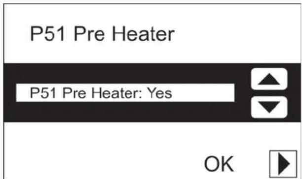
- Using "or", select the required P submenu, e.g. "P51 PRE HEATER".
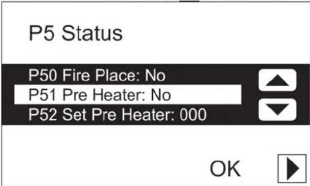
10. Press "OK" to confirm the P menu selected.
Entering settings in P menus
The procedure is as follows:
- Using "▲" or "▼", select a value for the parameter.
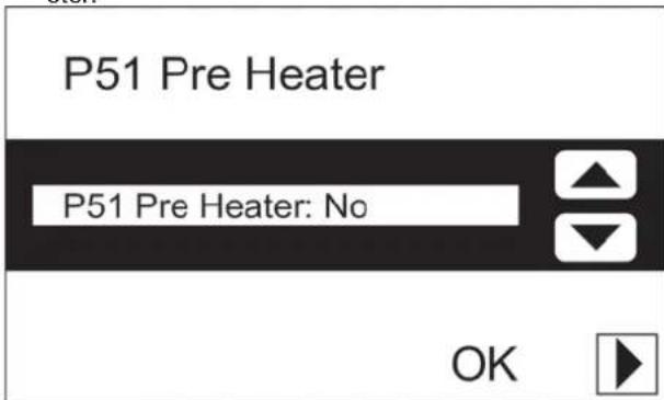
- Press "▶ to confirm the parameter's new value.
13. If necessary, press "▶" again to return to the P menus.
14. Repeat steps 7 to 13 to enter multiple parameters.

The minimum and maximum values for the available settings parameters are preset in the software.
Returning to the main menu
The procedure is as follows:
- Press "▶" to return to the "INSTALLATION MENU".
16. Press "▶ again to return to the main screen.

After five minutes, the ComfoControl will return automatically to the main screen.

Once parameters have been set in the P menus, the ComfoControl returns almost immediately to the main screen. However, this will take longer after a system reset (see Menu P7), as the system then has to reboot.
Zehnder Group Services
Zehnder Comfosystems
7, rue Jean Mermoz
ZA St Guénault
Courcouronnes
F-91031-Evrycedex
A division of Zehnder Group UK Ltd
Unit 1, Brookside Avenue
Rustington
West Sussex
BN163LF
Tel: 01903 777333
Fax: 01903 782398
Email: technical.comfosystems@zehndergroup.com
Website: www.comfosystems.co.uk

- Installingen make in P-menu's
- Table of Contents
- INTRODUCTION 1
- FOR THE USER 1
- FOR THE FITTER 10
- Introduction
- Preface
- Read this manual carefully before use.
- NOTE
- Guarantee and liability
- General
- Warranty conditions
- The warranty becomes invalid if:
- Liability
- Safety regulations
- Pictograms used
- Point of attention.
- Risk of:
- For the user
- ComfoControl
- Using ComfoControl
- Time and date settings
- Comfort temperature settings
- Comfo unit
- Ventilation volume settings
- The ComfoControl will display "AUTOC standards during manual ventilation, and not "MHN
- Switching extractor hood on/off
- The extractor hood symbol (1) then appears on the ComfoControl display.
- Note!
- The extractor hood symbol ("disappears from the ComfoControl display once the programmed time delay has run its course.
- Switching the supply and exhaust fan on/off
- Setting the ventilation programme
- Temperature programme settings
- Setting the temperature programme.
- Time delay settings
- Temperature correction settings
- Screen settings
- Language settings
- System data
- ComfoControl error messages
- What to do in the event of a malfunction
- ComfoControl fi Iter warning
- To replace (or clean) any fi iters, please refer to your ventilation system's user manual.
- Information about ComfoControl status
- End of useful life
- For the Fitter
- Installation conditions
- Installing ComfoControl
- Transport and unpacking
- Make sure the packing material is disposed of in an environmentally friendly manner.
- Checking the delivery
- Wall mounting
- Connection to ventilation system
- Connection to external temperature sensor
- Commissioning the ventilation and cooling system
- Accessing P menus
- The P menus are now accessible
- Entering settings in P menus
- Returning to the main menu
Brand : ZEHNDER
Model : ComfoControl Luxe
Category : Thermostat