
Wireless Phone Jack - Phone AUDIOLINE - Free user manual and instructions
Find the device manual for free Wireless Phone Jack AUDIOLINE in PDF.



| Brand | AUDIOLINE |
| Model | Wireless Phone Jack |
| Product type | Cordless phone extension |
| Category | Telephone |
| Box contents | 1 base, 1 extension, 1 phone cord, 1 manual |
| Power supply | Mains power outlet (built-in AC adapter) |
| Maximum range | Approximately 50 meters indoors |
| Maximum number of extensions | 4 extensions per base |
| Main functions | Cordless extension for telephone line, modem, fax, satellite/cable box |
| LED indicators | Green, yellow, red lights depending on status and mode |
| Mode setting | Switch S (voice) and C (data) |
| Dimensions (approx.) | Base and extension: 10 x 8 x 4 cm (estimate) |
| Weight (approx.) | Approximately 150 g per unit (estimate) |
| Standards and certifications | CE, directive 1999/5/EC |
| Safety and warnings | Indoor use only, do not use in explosive areas, disconnect by plug |
| Maintenance and cleaning | Not specified in the manual; clean with a soft, dry cloth |
| Spare parts and repairability | Not specified; contact the retailer or manufacturer |
| General information | Manufactured by RTX Products A/S, website www.wireless-phonejack.com |
Frequently Asked Questions - Wireless Phone Jack AUDIOLINE
User questions about Wireless Phone Jack AUDIOLINE
0 question about this device. Answer the ones you know or ask your own.
Ask a new question about this device
Download the instructions for your Phone in PDF format for free! Find your manual Wireless Phone Jack - AUDIOLINE and take your electronic device back in hand. On this page are published all the documents necessary for the use of your device. Wireless Phone Jack by AUDIOLINE.
USER MANUAL Wireless Phone Jack AUDIOLINE
50 meter wireless phone line
UserManual
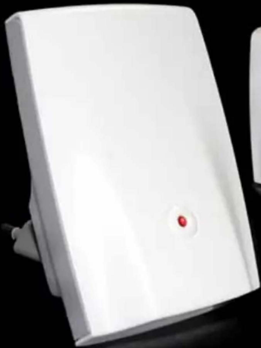
natural_image
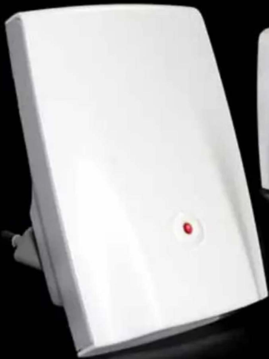
White electronic device with a red circular button on its side, against a black background (no text or symbols visible)
natural_image
White rectangular device with a small red dot on its surface (no text or symbols visible)1 minute
plug and play installation

RTX TECHNOLOGY
INSTALLATION GUIDE
ENGLISH 4
FRANÇAIS 11
ITALIANO 19
ESPAÑOL 27
POLSKI 35
NEDERLANDS 43
DEUTSCH 51
ελληνικά 59
SVENSKA 67
DANSK/NORSK 75
SUOMI....83
DEAR CUSTOMER
We would like to thank you for purchasing our Wireless Phone additional Extension unit. We hope you will enjoy it.
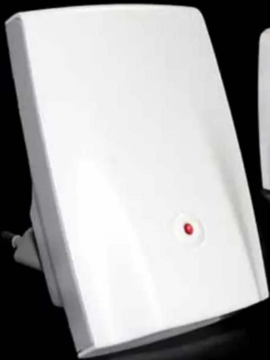
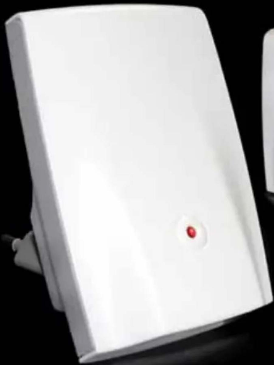
The Wireless Phone Jack is a wireless and cable free extension socket or VoIP adapter for an ordinary phone, modem, fax or satellite/cable set top box with integrated modem.
Please read the following thoroughly and observe the operating instructions and information provided.
Please visit our website for additional information: www.wireless-phonejack.com
Conformity of the Wireless Phone Jack to EU directives is confirmed by the CE symbol. Hereby, we declare that the Wireless Phone Jack and/or extra Extension units are in compliance with the essential requirements and other relevant provisions of Directive 1999/5/EC.
CE
Copyright ©. All rights reserved. All forms of copying or reproduction of the product or its associated user manual are strictly prohibited.
This product is manufactured for RTX Products HK Ltd.
UNPACKING
Carefully remove units from the packaging. If there is any visible damage DO NOT attempt to operate the Wireless Phone Jack. Contact your dealer or shipping carrier immediately.
BOX CONTENTS:
1) One Base unit
2) One Extension unit
3) One phone line cord
4) This user manual
text_image
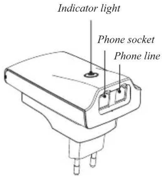
Indicator light Phone socket Phone line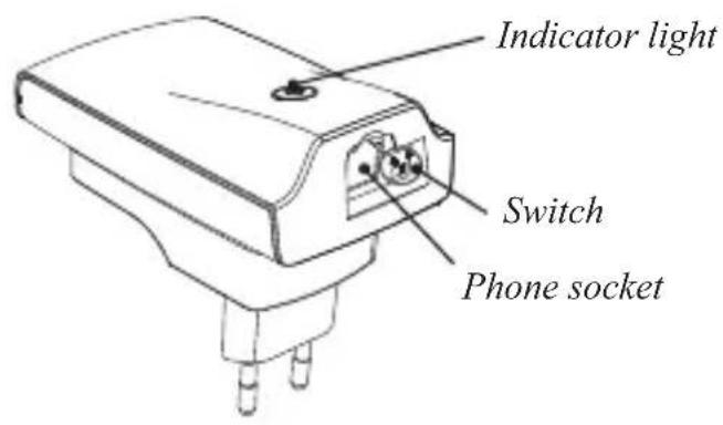
text_image
Indicator light Switch Phone socket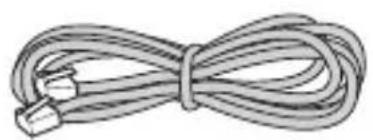
natural_image
Coiled cable or wire with two connectors at ends (no text or symbols)NOTE: Please read and follow carefully the instructions.
BASE UNIT INSTALLATION
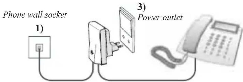
1) Connect the enclosed phone line cord to the Base unit and connect the other end to the phone wall socket.*
2) If you have a phone connected to the wall socket, unplugitan the Base unit instead (remove plug adapter before connecting to the Base unit).
3) Connect the Base unit to a power outlet and switch power on. The the Base unit should now glow green.
TheBaseunitisnow installed.
text_image
Phone wall socket 1) 3) Power outlet2) Phone, dial-up modem, fax
*NOTE: Works also as a wireless extension to a VoIP Terminal Adapter
EXTENSION UNIT INSTALLATION
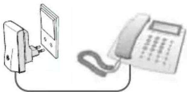
The Extension unit can be connected to either a normal phone, dial-up modem, fax or satellite/cablesettopbox.
1) Plug the phone line cord from your phone, dial-up modem, fax or satellite/cable set top box into the Extension unit.
1)
Power supply plug
natural_image
Illustration of a wall-mounted power plug connected to a landline telephone (no text or symbols present)Phone, dial-up modem, fax or satellite/cable set top box
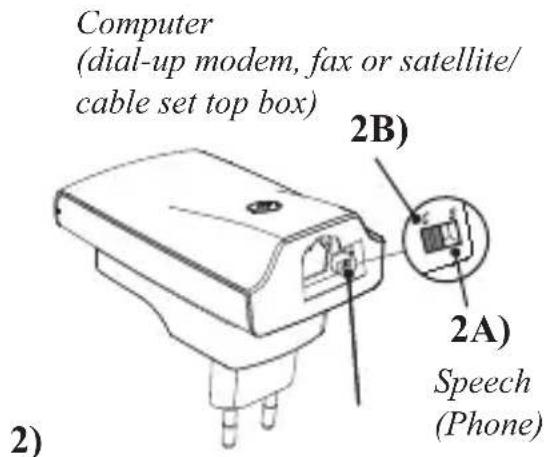
2)2A: Connection of phone. Turn the switch to "S"-position for Speech (voice). 2B: Connection of dial-up modem, fax or satellite/cable set top box. Turn the switch to "C"-position for Computer (dial-up modem, fax or satellite/cable set top box).
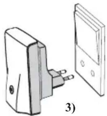
3) Plug the Extension unit into a power outlet and switch the power on top of the Extension unit will after a short period glow grey is on C) or yellow (if the switch is on S).
The Extension unit is now installed and your Wireless Phone Jack is now ready for use.
text_image
Computer (dial-up modem, fax or satellite/ cable set top box) 2B) 2A) Speech (Phone) 2)Extension unit
natural_image
Illustration of a wall-mounted electrical plug and its side panel (no text or symbols)INSTALLATION OF EXTRA EXTENSION UNITS
1) Makesure the existing Wireless Phone Jacksystem (base and is powered on.
2) UnpluganycordsattachedtotheBaseunit (thesewillbecon later).
3) Plug the extra Extension unit into a power outlet near the Bas power on. This will activate a red light on the Extension unit
4) PlugoneendofthesuppliedphonelinecordintotheBase unit and the other end into the extra Extension unit. A red light will be activated before changing to either green (if the switch is turned over to C = computer for dial-up modem, fax or set top box) or yellow (if the switch is turned over to S = speech for phone). This can take up to a minute.
5) Once the light changes on the Extension unit, unplug the phon between the Base unit and the Extension unit.
6)Replug the cord s w h i c h y o u h a v e u n p l u g g e d.
Go to page 4 Extension unit installation to finish the installation process.
OPERATING MODES
| BASE UNIT | ||
| Light shows This means | Suggested fix | |
| Steady Green Base unit is ready | No Extension units are in use | NoneNormal operation |
| Flashing Green One or more | Extension units are in use | NoneNormal operation |
| No Light No power to | Base unit | Check that the Base unit is properly connected to a power outlet and that the power is on |
| Fast flashing Green The base | unit is open for DECT handset registrations | The DECT handset registration mode is open after two power on-off operations. To terminate the registration mode, either register a DECT handset or turn the base power off and then on. |
| EXTENSION UNIT | ||
| Light shows This means | Suggested fix | |
| Steady Green Extension unit | in computer/Data (“C”) is registered and in range of Base unit and ready for use | NoneNormal operation |
| Steady Yellow Extension unit | in Speech/voice (“S”) is registered and in range of Base unit and ready for use | NoneNormal operation |
| Flashing Green Extension unit | in use (C mode) | NoneNormal operation |
| Flashing Yellow Extension unit | in use (S mode) | NoneNormal operation |
| No Light No power to Extension unit | Check that the Extension unit is properly connected to a power outlet and that the power is on | unit is properly connected to a power outlet and that the power is on |
| Steady Red Extension unit is | ready to be registered to a Base unit | See Installation of extra Extension units |
| Flashing Red to Yellow or Flashing Red to Green | Extension unit is registered but not locked to Base unit | Check that Base unit is powered up. If it is, the Extension unit may be out of range of Base unit. Relocate either the Extension unit or the Base unit to bring the units closer together |
| Fast flash of Red for 5 seconds followed by Steady Red (occurring after an attempt to register an Extension unit) | Four Extension units are already registered to the Base unit (the max possible) – this fifth Extension unit cannot be added | Install an additional Base unit and register the fifth Extension unit to the new Base unit |
TROUBLESHOOTING
| Problem Possible cause | Solution | |
| Nodialingtoneava | ilable -Baseunitpower-Cablesnotcorrectly connected-The Extension unit may not be registered to the base-The Extension unit is of reach | n-Checkallpowerandcablections. If in doubt please refer to the user manual. Check that the Extension unit switch is correctly set to either S or CRelocatetheExtensionunsignal reach of the Base unit (max 50m) |
| My dial-up modem/set top box/faxis not working | The Extension unit switch has not been set to modem functionality | Make sure that the Extension unit switch is set to C |
| Short “hissing” sound heard on phone attached to the Extension unit when first picked up | The Extension unit switch has not been set properly | Make sure that the Extension unit switch is set to S |
| The extra extension unit is blinking before starting a registration procedure | The extra extension unit is already registeredtoanother phone jack | Turn power on-off, 5 times in a row until the light is continuousHereafter continue extra extension extension unit installation |

The lightning flash with arrowhead symbol within an equilateral triangle is led to alert the user to the presence of uninsulated “dangerous voltage” within product’s enclosure that may be of sufficient magnitude to constitute a risk of shock to persons.
“Caution” Main plug is used as disconnect device and it should remain readily operable during intended use. In order to disconnect the apparatus from the mains completely, the mains plug should be disconnected from the mains socket outlet completely.
The socket outlet shall be installed near the equipment and shall be easily accessible.
Warning:
- Do not use this equipment in places where volatile or explosive materials may be present.
- This equipment will be inoperable if mains power fails.
- For indoor use only.

The crossed-out wheeled bin symbol that can be found on your product means that the product is covered by the European Directive 2002/96/EC and it indicates that this product should not be disposed of via the normal household waste stream.
To prevent possible harm to the environment or human health, please separate this product from other waste streams to ensure that it can be recycled in an environmentally sound manner. For more details on available collection facilities, please contact your local govern office or the retailer where you purchased this product.
WIRELESS
PHONE Jack ^TM
50 meter wireless phone line
natural_image
White rectangular electronic device with a red circular button on its side, against a black background (no visible text or symbols)
natural_image
White rectangular object with a small red dot at its center, against a black background (no text or symbols visible)Installazione plug and play in
un minuto

RTX TECHNOLOGY
Cher client,
natural_image
Coiled cable or wire with connectors, no text or symbols visiblenatural_image
Illustration of a wall-mounted device connected to a landline telephone (no text or symbols present)50 meter wireless phone line
Manuale d'uso
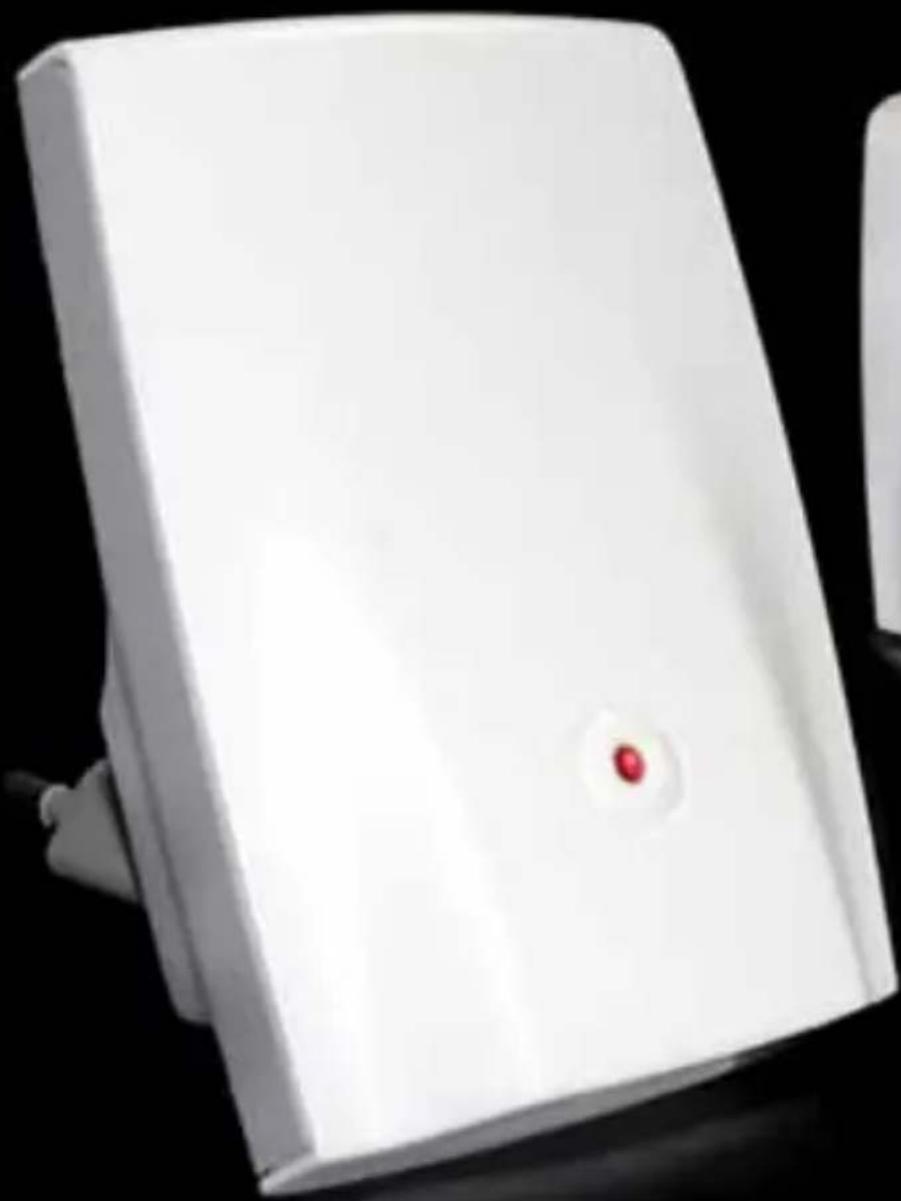
natural_image
White rectangular electronic device with a red circular button on its side, against a black background (no visible text or symbols)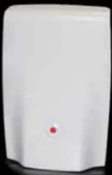
natural_image
White rectangular device with a small red dot on its surface (no visible text or symbols)Installation
<
une minute

RTX TECHNOLOGY
GENTILE CLIENTE
natural_image
Illustration of a coiled cable or wire with connectors (no text or symbols)natural_image
Illustration of a plug connected to a telephone and a wall-mounted device (no text or symbols present)Telefono, modem, fax o decoder satellitare o via cavo
natural_image
Illustration of a wall-mounted electrical plug and its side panel (no text or symbols)3)
Unità di estensione
50 meter wireless phone line
Manual de usuario
natural_image
White rectangular electronic device with a red circular button on its side, against a black background (no visible text or symbols)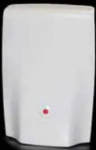
natural_image
White rectangular device with a small red dot on its surface (no visible text or symbols)natural_image
Coiled cable with connectors, no text or symbols visiblenatural_image
Illustration of a plug connected to a telephone and a wall-mounted device (no text or symbols present)natural_image
Illustration of a wall-mounted electrical plug and its side panel (no text or symbols)50 meter wireless phone line
natural_image
White rectangular electronic device with a red circular button on its side, against a black background (no text or symbols visible)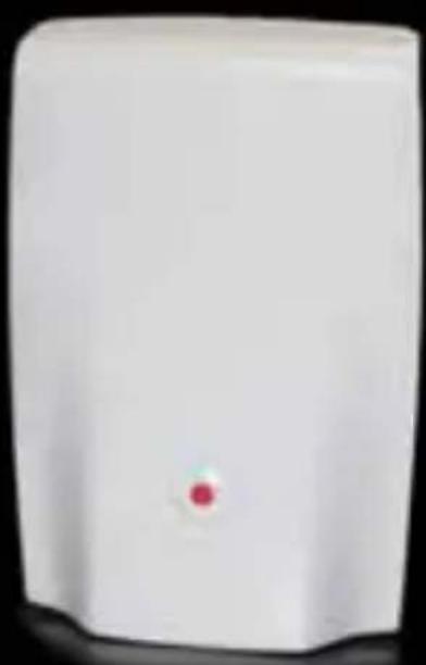
natural_image
White rectangular device with a small red dot on its surface (no visible text or symbols)1-minutowa
instalacja
plug & play

RTX TECHNOLOGY
SZANOWNI PAŃSTWO!
natural_image
Coiled cable or wire with two connectors, no text or symbols visiblenatural_image
Illustration of a wall-mounted power plug connected to a telephone and a separate card (no text or symbols present)natural_image
Illustration of a device with two pins and a separate panel (no text or symbols)50 meter wireless phone line
natural_image
White rectangular electronic device with a red circular button on its side, against a black background (no visible text or symbols)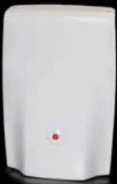
natural_image
White rectangular device with a small red dot on its surface (no visible text or symbols)Plug-en-play installatie in
1 minuut

RTX TECHNOLOGY
BESTE KLANT
natural_image
Coiled cable with connectors, no text or symbols visiblenatural_image
Illustration of a wall-mounted electrical plug and its corresponding electronic device (no text or symbols visible)INSTALLATIE VAN EXTRA UITBREIDINGSEENHEDEN
50 meter wireless phone line
Benutzerhandbuch
natural_image
White rectangular electronic device with a red circular button on its side, against a black background (no text or symbols visible)
natural_image
White rectangular device with a small red dot on its surface (no visible text or symbols)Plug-and-play-Installation in
1 Minute

RTX TECHNOLOGY
LIEBER KUNDE,
natural_image
Coiled cable or wire with connectors, no text or symbols visiblenatural_image
Illustration of a small electrical plug and its corresponding meter (no text or symbols present)natural_image
White rectangular electronic device with a red circular button on its side, against a black background (no visible text or symbols)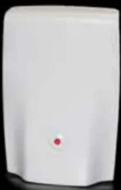
natural_image
White rectangular device with a small red dot on its surface (no text or symbols visible)1 ΛΕΠΤΟ
ΕΓΚΑΤΑΣΤΑΣΗΣΕ

RTX
TECHNOLOGY
Αγαπητέ μας πελάτη,
natural_image
Illustration of a coiled cable with connectors (no text or symbols)natural_image
Simple line drawing of a mechanical or electrical component with a separate panel (no text or symbols)3)
Πρίζα ρεύματος
natural_image
Illustration of a classic office telephone with keypad and cord (no visible text or symbols)2)
natural_image
Illustration of a wall-mounted electrical socket connected to a landline telephone (no text or symbols present)Πρίζα ρεύματος
natural_image
Illustration of a wall-mounted electrical plug and its side panel (no text or symbols)50 meter wireless phone line
Användarhandbok
natural_image
White electronic device with a red circular button on its side, against a black background (no visible text or symbols)
natural_image
White rectangular device with a small red dot on its surface (no visible text or symbols)1 minute
plug and play- installation

RTX TECHNOLOGY
BÄSTA KUND
natural_image
Coiled cable or wire with two connectors, no text or symbols visiblenatural_image
Illustration of a device with two pins and a separate panel (no text or symbols)INSTALLATION AV EXTRA ANKNYTNINGSENHETER
50 meter wireless phone line
Brugerhåndbog
text_image
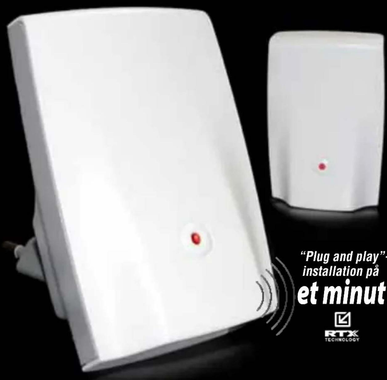
"Plug and play" installation på et minut RTX TECHNOLOGYINSTALLATION AF EXTENSION UNIT
Extension Unit kan forbindes til enten en almindelig telefon, et modem, en fax eller en digital set-top box.
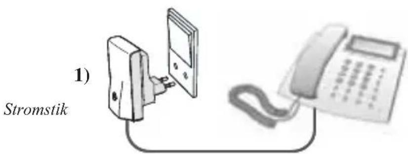
1) Sæt telefonkablet fra din telefon, dit modem, din fax eller din digitale set-top box i Extension unit.
text_image
1) StromstikTelefon, modem, fax eller digital set-top box
natural_image
Illustration of a device with two pins, shown from an open and side views (no text or symbols)3)
INSTALLATION AF EKSTRA EXTENSION UNITS
50 meter wireless phone line
Käyttöopas
natural_image
White electronic device with a red circular button on its side, against a black background (no visible text or symbols)
natural_image
White rectangular device with a small red dot on its surface (no visible text or symbols)1 minuutin
natural_image
Coiled cable with connectors, no text or symbols visiblenatural_image
Illustration of a wall-mounted device connected to a landline telephone (no text or symbols present)natural_image
Illustration of a wall-mounted electrical plug and its corresponding electronic device (no text or symbols present)Laajennusyksikko