
Butcher - Receiver PEAVEY - Free user manual and instructions
Find the device manual for free Butcher PEAVEY in PDF.

| Product Type | Tube Guitar Amplifier |
| Output Power | 100 W or 50 W (selectable) |
| Power Tubes | 4 x EL34 |
| Preamp Tubes | 5 x 12AX7 |
| Channels | Clean and Crunch with independent 3-band EQ |
| Punch Control | 12 positions on Crunch channel to adjust bass |
| Channel Boost | Pre-gain boost switches on both channels |
| Master Section | Two master volumes with selector switch, presence control |
| Effects Loop | With send and return level controls |
| Direct Output | XLR with MSDI™ microphone simulation, Tone and Ground Lift settings |
| MIDI Control | MIDI compatible (5-pin cable) and included footswitch (8-pin) |
| Included Footswitch | Channel switching, boost, effects loop, and master volume |
| Speaker Impedance | 4/8/16 Ω selector, parallel 1/4" outputs |
| Power Supply | 120 V~, 60 Hz, 300 W |
| Fuse | FSAL/250V (replace with identical type) |
| Maintenance | Clean with a dry cloth only |
| Safety | Do not expose to moisture or liquids; refer repairs to a qualified technician |
| Spare Parts and Repairability | No user-serviceable parts inside; contact a Peavey authorized repair center |
| Dimensions | Not specified in the manual |
| Weight | Not specified in the manual |
Frequently Asked Questions - Butcher PEAVEY
User questions about Butcher PEAVEY
0 question about this device. Answer the ones you know or ask your own.
Ask a new question about this device
Download the instructions for your Receiver in PDF format for free! Find your manual Butcher - PEAVEY and take your electronic device back in hand. On this page are published all the documents necessary for the use of your device. Butcher by PEAVEY.
USER MANUAL Butcher PEAVEY
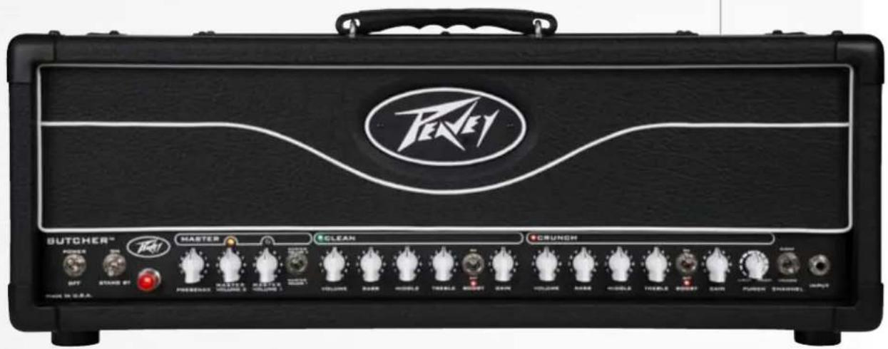
Butcher™ Guitar Amplifier
Operating Manual
ENGLISH 15
FRANÇAIS 24
DEUTSCH 30
ITALIANO 36
ESPAÑOL 42
中文 48
PORTUGUÊS ...... 54
日本語 60
한국어 66

Intended to alert the user to the presence of uninsulated "dangerous voltage" within the product's enclosure that may be of sufficient magnitude to constitute a risk of electric shock to persons.
Intended to alert the user of the presence of important operating and maintenance (servicing) instructions in the literature accompanying the product.

CAUTION: Risk of electrical shock — DO NOT OPEN!
CAUTION: To reduce the risk of electric shock, do not remove cover. No user serviceable parts inside. Refer servicing to qualified service personnel.
WARNING: To prevent electrical shock or fire hazard, this apparatus should not be exposed to rain or moisture, and objects filled with liquids, such as vases, should not be placed on this apparatus. Before using this apparatus, read the operating guide for further warnings.

IMPORTANT SAFETY INSTRUCTIONS
WARNING: When using electrical products, basic cautions should always be followed, including the following:
-
Read these instructions.
-
Keep these instructions.
-
Heed all warnings.
-
Follow all instructions.
-
Do not use this apparatus near water.
-
Clean only with a dry cloth.
-
Do not block any of the ventilation openings. Install in accordance with manufacturer's instructions.
-
Do not install near any heat sources such as radiators, heat registers, stoves or other apparatus (including amplifiers) that produce heat.
-
Do not defeat the safety purpose of the polarized or grounding-type plug. A polarized plug has two blades with one wider than the other. A grounding type plug has two blades and a third grounding plug. The wide blade or third prong is provided for your safety. If the provided plug does not fit into your outlet, consult an electrician for replacement of the obsolete outlet.
-
Protect the power cord from being walked on or pinched, particularly at plugs, convenience receptacles, and the point they exit from the apparatus.
-
Only use attachments/accessories provided by the manufacturer.
-
Use only with a cart, stand, tripod, bracket, or table specified by the manufacturer, or sold with the apparatus. When a cart is used, use caution when moving the cart/apparatus combination to avoid injury from tip-over.
-
Unplug this apparatus during lightning storms or when unused for long periods of time.
-
Refer all servicing to qualified service personnel. Servicing is required when the apparatus has been damaged in any way, such as power-supply cord or plug is damaged, liquid has been spilled or objects have fallen into the apparatus, the apparatus has been exposed to rain or moisture, does not operate normally, or has been dropped.
-
Never break off the ground pin. Write for our free booklet "Shock Hazard and Grounding." Connect only to a power supply of the type marked on the unit adjacent to the power supply cord.
-
If this product is to be mounted in an equipment rack, rear support should be provided.
-
Note for UK only: If the colors of the wires in the mains lead of this unit do not correspond with the terminals in your plug, proceed as follows: a) The wire that is colored green and yellow must be connected to the terminal that is marked by the letter E, the earth symbol, colored green or colored green and yellow. b) The wire that is colored blue must be connected to the terminal that is marked with the letter N or the color black. c) The wire that is colored brown must be connected to the terminal that is marked with the letter L or the color red.
-
This electrical apparatus should not be exposed to dripping or splashing and care should be taken not to place objects containing liquids, such as vases, upon the apparatus.
-
The on/off switch in this unit does not break both sides of the primary mains. Hazardous energy can be present inside the chassis when the on/off switch is in the off position. The mains plug or appliance coupler is used as the disconnect device, the disconnect device shall remain readily operable.
-
Exposure to extremely high noise levels may cause a permanent hearing loss. Individuals vary considerably in susceptibility to noise-induced hearing loss, but nearly everyone will lose some hearing if exposed to sufficiently intense noise for a sufficient time. The U.S. Government's Occupational Safety and Health Administration (OSHA) has specified the following permissible noise level exposures:
Duration Per Day In Hours Sound Level dBA, Slow Response
| 8 90 | |
| 6 92 | |
| 4 95 | |
| 3 97 | |
| 2 100 | |
| 1 1/2 102 | |
| 1 105 | |
| 1/2 | 110 |
| 1/4 or less | |
According to OSHA, any exposure in excess of the above permissible limits could result in some hearing loss. Earplugs or protectors to the ear canals or over the ears must be worn when operating this amplification system in order to prevent a permanent hearing loss, if exposure is in excess of the limits as set forth above. To ensure against potentially dangerous exposure to high sound pressure levels, it is recommended that all persons exposed to equipment capable of producing high sound pressure levels such as this amplification system be protected by hearing protectors while this unit is in operation.
SAVE THESE INSTRUCTIONS!
a) The wire that is colored green and yellow must be connected to the terminal that is marked by the letter E, the earth symbol, colored green or colored green and yellow.
b) The wire that is colored blue must be connected to the terminal that is marked with the letter N or the color black.
c) The wire that is colored brown must be connected to the terminal that is marked with the letter L or the color red.
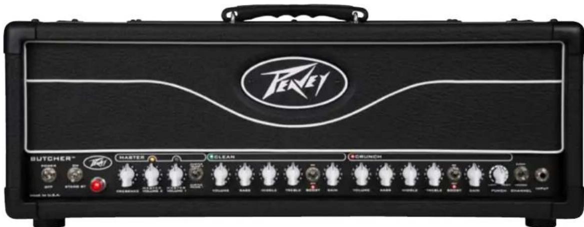
Butcher™ Guitar Amplifier
This newest Peavey guitar amplifier harkens back to the tones of classic rock while offering unique modern features. The Butcher is a two-channel amplifier with five 12AX7 preamp tubes and four EL34 power amp tubes. Both the Clean and Crunch channels feature independent three-band EQ, plus channel volume and preamp gain controls so guitarists can adjust the interplay between the preamp and power amp on each channel for an array of gain possibilities. Both channels include a separate, footswitchable gain boost, while the Crunch channel also has a 12-way Punch selector that adjusts the low-end attack of the amplifier—a handy feature that helps match the head to various playing styles at different levels of gain. The master section widens the range of possibilities with two footswitchable master volumes, so players can set one as a default and use the second as a solo boost and a Presence control that boosts the extreme high frequencies, giving the amp extra cut. On the rear panel, the built-in Peavey MSDI ^™ microphone-simulated XLR direct interface eliminates the need for miking by allowing users to send the amp's signal directly to a recording device or mixing console. Additional controls include an active effects loop with send and return level control, an impedance selector and a half-power switch, allowing you to rock the Butcher in either 50-watt or 100-watt mode.
Features:
- Two channels; Clean and Crunch
• 4xEL34 100W power section & 5x12AX7 preamp tubes - Separate three band EQ on each channel
• Global presence control - Two Master Volume controls for additional boost capabilities
• 12-way 'punch' control on channel 2 - Pre-Gain boost switch on both channels
• Built in MSDI microphone simulated direct XLR output
• Active effects loop with send and return level - Impedance selector
- Half Power switch
• MIDI control capability
- Included footswitch controls channel, boosts, loop and master volume switching

VENTILATION: For proper ventilation, allow 12" clearance from the nearest combustible surface.
All vents should have a minimum of 2" of free air space so air can flow thru the unit freely for proper cooling.
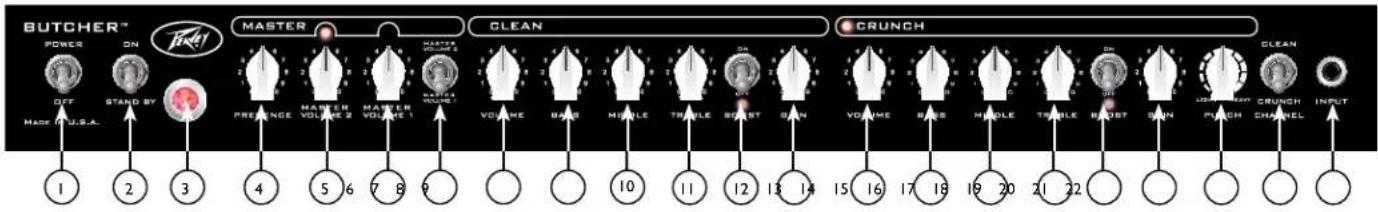
POWER SWITCH
This two-way toggle switch applies mains power to the unit. The power status lamp (3) will illuminate when this switch is in the ON position.
STANDBY SWITCH
This two-way toggle switch allows the amp to be placed in the STANDBY mode. In the STANDBY position, the tubes stay hot but the amplifier is not operational. Switching to the ON position places the amp in Active mode.
MASTER SECTION
PRESENCE CONTROL
Power amp tone control that adjusts the high-frequency damping in the power amp.
MASTER VOLUME 2
This control allows the user to set a second Master Volume at a different level than the Master Volume 1 (e.g. louder).
MASTER VOLUME 1
This control sets the overall volume level of the amp. Once the desired balance between the two channels in the amplifier has been achieved, the entire output level of the unit can be increased or decreased by rotating this control. Clockwise rotation increases the level; counterclockwise rotation decreases the level.
MASTER VOLUME SWITCH
This switch toggles between MASTER VOLUME 1 (6) and MASTER VOLUME 2 (5). This feature is switchable via the footswitch or via MIDI. For a complete list of MIDI commands, please refer to page 12 of this owner's manual.
CLEAN CHANNEL
VOLUME CONTROL
This sets the volume of the Clean channel.
BASS
This control varies the low-frequency response of the Clean channel.
MIDDLE
This control varies the mid-frequency response of the Clean channel.
TREBLE
This control varies the high-frequency response of the Clean channel.
CHANNEL BOOST
This switch activates a preamp boost in the Clean channel for a pronounced overdrive. This feature is switchable via the footswitch or via MIDI. For a complete list of MIDI commands, please refer to page 12 of this owner's manual.
CHANNEL GAIN
This control controls the input volume level of the Clean channel. Rotating this control clockwise will increase the amount of preamp distortion and sustain.
CRUNCH CHANNEL
VOLUME CONTROL
This sets the volume for the Crunch channel.
BASS
This control varies the low-frequency response of the Crunch channel.
MIDDLE
This control varies the mid-frequency response of the Crunch channel.
TREBLE
This control varies the high-frequency response of the Crunch channel.
CHANNEL BOOST
This switch activates a preamp boost in the Crunch channel for more gain. This feature is switchable via the footswitch or via MIDI. For a complete list of MIDI commands, please refer to page 12 of this owner's manual.
GAIN
This control adjusts the input volume level of the Crunch channel. Rotating this control clockwise will increase the amount of preamp distortion and sustain.
CRUNCH CHANNEL "PUNCH" CONTROL
This 12-way selector that adjusts the low-end attack of the amplifier—a handy feature that helps match the head to various playing styles.
CHANNEL SELECT SWITCH
This two-position toggle switch allows selection between the amplifier's Clean and Crunch channels. LED illumination indicates which channel is active. Channel switching can also be accomplished by footswitch or via MIDI control.
INPUT
This 1/4" jack is designed to accommodate any guitar output signal.
![EFFECTS LOOP [RET BOTH CONTROLS TO HANNUOW-SRITCH FULL VOLUME] SEND LEVEL SEND RETURN RETURN LEVEL MSSI-TONE GROUND LIFT BRIGHT NORMAL DARK MSSI"LEVEL MSSI" SWEER IMPEDANCE OUTRUN 100W 4 8 76 WIRCHPHONE SIMULATED DEEP ROLL SOW 8 16 DHMS SWEER IMPEDANCE FOR SPREADS JACKS SIMULATED 100 WATTS CAUTION FREE OF ELECTRIC SHOCK AND FLOW ON LEMONAL BEANS FOR POWER INLETION BEANS FOR POWER INLETION BEANS FOR POWER INLETION BEANS FOR POWER INLETION BEANS FOR POWER INLETION BEANS FOR POWER INLETION BEANS FOR POWER INLETION BEANS FOR POWER INLETION BEANS FOR POWER INLETION BEANS FOR POWER INLETION BEANS FOR POWER INLETION BEANS FOR POWER INLETION BEANS FOR POWER INLETION BEANSFOR POWER INLETION BEANSFOR POWER INLETION BEANSFOR POWER INLETION BEANSFOR POWER INLETION BEANSFOR POWER INLETION BEANSFOR POWER INLETION BEANSFOR POWER INLETION BEANSFOR POWER INLETION BEANSFOR POWER INLETION BEANSFOR POWER INLETION BEANSFOR POWER INLETION BEANSFOR POWER INLETION BEANSFOR POWER INLETATION BEANSFOR POWER INLETATION BEANSFOR POWER INLETATION BEANSFOR POWER INLETATION BEANSFOR POWER INLETATION BEANSFOR POWER INLETATION BEANSFOR POWER INLETATION BEANSFOR POWER INLETATION BEANSFOR POWER INLETATION BEANSFOR POWER INLETATION BEANSFOR POWER INLETATION BEANSFOR POWER INLETATION BEANSFOR POWER INLETATION BEANSFORMER POWER INLETATION BEANSFORMER POWER INLETATION BEANSFORMER POWER INLETATION BEANSFORMER POWER INLETATION BEANSFORMER POWER INLETATION BEANSFORMER POWER INLETATION BEANSFORMER POWER INLETATION BEANSFORMER POWER INLETATION BEANSFORMER POWER INLETATION BEANSFORMER POWER INLETATION BEANSFORMER POWER INLETATION BEANSFORMER Power INLETATION BEANSFORMER Power INLETATION BEANSFORMER Power INLETATION BEANSFORMER Power INLETATION BEANSFORMER Power INLETATION BEANSFORMER Power INLETATION BEANSFORMER Power INLETATION BEANSFORMER Power INLETATION BEANSFORMER Power INLETATION BEANSFORMER Power INLETATION BEANSFORMER Power INLETATION BEANSFORMER PowerINLETATION BEANSFORMER PowerINLETATION BEANSFORMER PowerINLETATION BEANSFORMER PowerINLETATION BEANSFORMER PowerINLETATION BEANSFORMER PowerINLETATION BEANSFORMER PowerINLETATION BEANSFORMER PowerINLETATION BEANSFORMER PowerINLETATION BEANSFORMER PowerINLETATION BEANSFORMER PowerINLETATION BEANSFORMER PowerINLOTATION BEANSFORMER PowerINLOTATION BEANSFORMER PowerINLOTATION BEANSFORMER PowerINLOTATION BEANSFORMER PowerINLOTATION BEANSFORMER PowerINLOTATION BEANSFORMER PowerINLOTATION BEANSFORMER PowerINLOTATION BEANSFORMER PowerINLOTATION BEANSFORMER PowerINLOTATION BEANSFORMER PowerINLOTATION BEANSFORMER PowerINLOTITION BEANSFORMER PowerINLOTITION BEANSFORMER PowerINLOTITION BEANSFORMER PowerINLOTITION BEANSFORMER PowerINLOTITION BEANSFORMER PowerINLOTITION BEANSFORMER PowerINLOTITION BEANSFORMER PowerINLOTITION BEANSFORMER PowerINLOTITION BEANSFORMER PowerINLOTITION BEANSFORMER PowerINLOTITION BEANSFORMER PowerINLOTITION](/content/2026/02/381675/images/d09417f92c05ae43a60b6f3e8f78a2e7584fb1566807a63d6a9afecc38336ed2.jpg)
EFFECTS SEND LEVEL
This calibrated (-20dB to odB) control sets the level of signal being sent to external effects and/or signal processors. Clockwise rotation increases the amount of signal being sent; counterclockwise rotation decreases the amount. For unity gain, set both to odB (max) setting. Boost can be achieved by cutting Send or Return levels. The fact that both knobs cut allows for higher "level" settings on effects. All of this can be used to better optimize noise and avoid any chance of unwanted clipping in a given effect.
EFFECTS SEND / EFFECTS RETURN
These 1/4" mono (TS) jacks allow signal to be sent to and returned from external effects and/or signal processors. Using shielded cables with 1/4" mono (TS) phone plugs, patch from EFFECTS SEND to the input of the external device, and from the output of the external device to EFFECTS RETURN. If the footswitch is used, the EFFECTS SELECTOR switch must be depressed to activate the effects loop. See the FOOTSWITCH section of this manual for explanation of switch operation (page 9).
EFFECTS RETURN LEVEL
This calibrated (-1odB to odB) control sets the level of signal being returned from external effects and/or signal processors. Clockwise rotation increases the amount of signal being returned; counterclockwise rotation decreases the amount.
REMOTE SWITCH
This eight-pin DIN connector is provided for the connection of the remote footswitch. You must use the included eight-pin cable, as it supplies power to the footswitch. The Butcher can also be controlled remotely via MIDI using a standard five-pin MIDI cable. For a complete description of the MIDI commands, please refer to page 12 of this owner's manual.
MSDI ^TM
Microphone Simulated Direct Interface. Peavey's exclusive MSDI simulates the sound of a microphone near a real speaker cone, allowing the user to send a direct signal to the mixing console with a miked-cab sound. This is a non-powered output and safe for use with any mixing console. The MSDI also features a TONE control, GROUND LIFT and LEVEL control, enabling the front-of-house engineer to alter the tone to what is required for the best sound. The MSDI is a passive circuit that does not clip.
CABINET IMPEDANCE SWITCH
This three-position switch allows appropriate selection of speaker cabinet impedance. If two enclosures of equal impedance are used, the switch should be set to half the individual value. For example, two 16-ohm enclosures necessitate an 8-ohm setting, while two 8-ohm enclosures would require a 4-ohm setting. Minimum speaker impedance is 4 ohms. When the amplifier is set to half-power mode, the impedance selector uses the bottom row on the switch to indicate the impedance selection. In half-power mode, the minimum speaker impedance is 8 ohms.
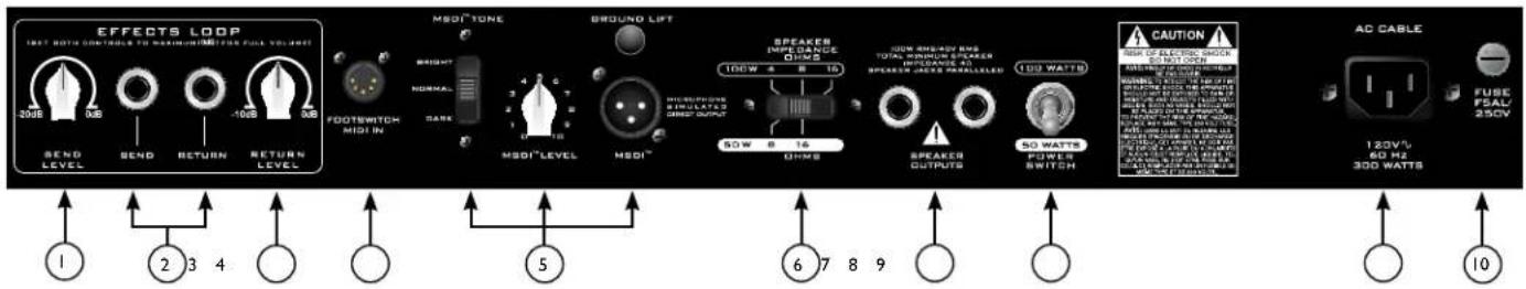
7 SPEAKER OUTPUTS
These paralleled 1/4" mono (TS) jacks are provided for the connection of speaker enclosure(s). Minimum speaker impedance is 4 ohms. The CABINET IMPEDANCE SWITCH (7) should be set to match the load of the speaker cabinet(s).
8 HALF POWER SWITCH
The Butcher is equipped with a half-power switch that reduces the maximum output power from 100 watts to 50 watts. 50-watt amplifiers have a different character than 100 watt amplifiers, overdriving more quickly and at slightly lower volumes. This switch is available for you to determine your own personal preferences and can be a versatile tool in the studio as well. The CABINET IMPEDANCE SWITCH (7) should be set to match the load of the speaker cabinet(s), as the settings will be different for half-power mode.
⑨ IEC MAINS CONNECTOR
This is a standard IEC power connector. An AC mains cord having the appropriate AC plug and ratings for the intended operating voltage is included in the carton. The mains cord should be connected to the amplifier before connecting to a suitable AC outlet.

U.S DOMESTIC AC MAINS CORD
The mains cord supplied with the unit is a heavy-duty, 3-conductor type with a conventional 120 VAC plug with ground pin. If the outlet used does not have a ground pin, a suitable grounding adapter should be used, and the third wire should be grounded properly.

Never break off the ground pin on any equipment. It is provided for your safety.

NOTE: FOR UK ONLY
If the colors of the wires in the mains lead of this unit do not correspond with the colored markings identifying the terminals in your plug, proceed as follows: (1) The wire that is colored green and yellow must be connected to the terminal that is marked by the letter E, the Earth symbol, colored green, or colored green and yellow. (2) The wire that is colored blue must be connected to the terminal that is marked with the letter N or the color black. (3) The wire that is colored brown must be connected to the terminal that is marked with the letter L or the color red.

FUSE
A fuse is located within the cap of the fuse holder. This fuse must be replaced with one of the same type and value to avoid damaging the amplifier and voiding the warranty. If the amp repeatedly blows the fuse, it should be taken to a qualified service center for repair.
WARNING: THE FUSE SHOULD ONLY BE REPLACED AFTER THE POWER CORD HAS BEEN DISCONNECTED.
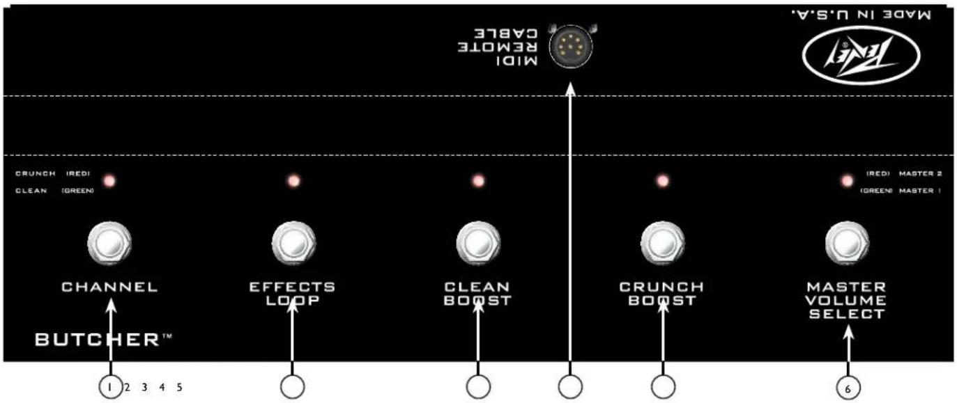
CHANNEL SWITCH
Toggles between the Clean channel and the Crunch channel.
EFFECTS LOOP ON/OFF SWITCH
Toggles the Effects Loop on or off. When the indicator light is lit, the Effects Loop is active.
CLEAN CHANNEL BOOST
Switches on the preamp boost on the Clean channel.
REMOTE CABLE JACK
Connect the included eight-pin cable to the amp's footswitch/MIDI input jack.
Note: You must use the included eight-pin cable, as it supplies the footswitch with power. When using an external MIDI source to control the amplifier, a five-pin MIDI cable can be used. Since the Butcher uses MIDI control, changes made to switches on the amplifier will be reflected by the LED's on the footswitch, and vice versa.
CRUNCH CHANNEL BOOST
Switches on the preamp boost on the Crunch channel.
MASTER VOLUME SELECT SWITCH
Toggles between the Two Master Volume controls.
Specifications
Power Amplifier Section:
Rated Power and Load:
100W(rms) into 16, 8 or 4 ohms (selectable impedance) 50W(rms) into 16 or 8 ohms (half-power switch engaged) Hum and Noise: Greater than 90 dB below rated power Power Consumption: Domestic: 300W, 60 Hz, 120 VAC Export: 300W, 50/60 Hz, 220-240 VAC
Preamp Section:
The following specs are measured @ 1kHz with the controls preset as follows:
Clean and Crunch Gains @ 5 Punch @ 6th CW position Low, Mid, and High EQ @ 5 Clean and Crunch Volumes @ 10 Effects Send and Return Levels @ odB Master Volumes @ 10 Power Level @ 100W Presence @ o
Clean Channel:
Nominal Input Level (no boost): -6.94 dBV, 450 mV rms Nominal Input Level (with boost): -20.0 dBV, 100 mV rms Input Impedance: 1M Ohms.
Crunch Channel:
Nominal Input Level (no boost): -8.40 dBV, 380 mV rms Nominal Input Level (with boost): -14.0 dBV, 200 mV rms Input Impedance: 1M Ohms.
Effects Send:
Load Impedance: 1k Ohms or greater Nominal Output Level: o dBV, 1.0 V(rms)
Effects Return:
Impedance: High Z, 1M Ohms Nominal Input Level: o dBV, 1.0 V(rms) (Switching jack provides Effects Send to Effects Return connection when not used)
Equalization:
Clean and Crunch channels: Low, Mid, and High passive EQ with dedicated voicings. Presence: High-frequency power amp feedback to the phase inverter.
Remote Footswitch:
Special 5-button unit with LED indicators (included)
Dimensions and Weight:
10.5" (267mm) H x 26.5" (673mm) W x 11.4" (290mm) D 50.8 lbs. (23.0 kg)
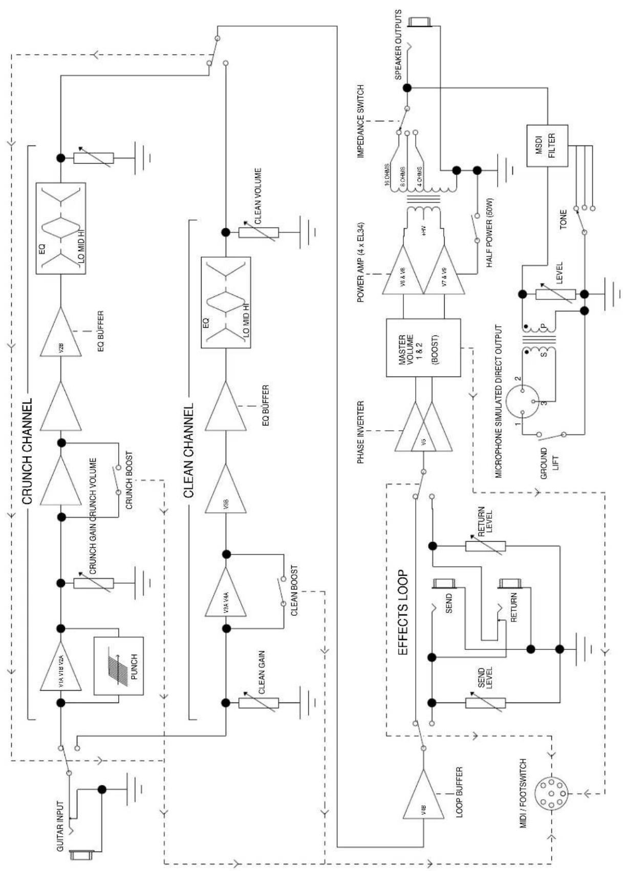
BUTCHER
FUNCTIONAL BLOCK DIAGRAM
flowchart
graph TD
    A["GUITAR INPUT"] --> B["Crunch Channel"]
    B --> C["PUNCH"]
    B --> D["CRUNCH GAIN CRUNCH VOLUME"]
    B --> E["CRUNCH BOOST"]
    B --> F["EQ BUFFER"]
    F --> G["LO MID HI"]
    G --> H["CLEAN CHANNEL"]
    H --> I["CLEAN GAIN"]
    H --> J["CLEAN BOOST"]
    H --> K["EO Q BUFFER"]
    K --> L["LO MID HI"]
    L --> M["CLEAN VOLUME"]

    N["EFFECTS LOOP"] --> O["VOB LOOP BUFFER"]
    O --> P["MIDI / FOOTSWITCH"]

    Q["PHASE INVERTER"] --> R["VO5 MASTER VOLUME 1 & 2 (BOOST)"]
    R --> S["POWER AMP (4 x EL34)"]
    S --> T["V6 & V8"]
    T --> U["V7 & V9"]
    U --> V["+HV"]
    V --> W["HALF POWER (50W)"]
    W --> X["SPEAKER OUTPUTS"]

    Y["MICROPHONE SIMULATED DIRECT OUTPUT"] --> Z["GROUND LIFT"]
    Z --> AA["3 S P LEVEL"]
    AA --> AB["TONE"]
    AB --> AC["MSDI FILTER"]
BUTCHER™ MIDI IMPLEMENTATION
| MIDI Channel Select | ||||||
| Via System Exclusive: | Hex: F0 00 00 1B 14 01 75 ch F7 ... where ch is 00-0F (MIDI channel 1-16) | |||||
| Via Butcher footswitch: | Hold the last footswitch (Master) for 2 seconds to enter MIDI channel select mode. | |||||
| The LEDs on the first four footswitches will blink. You can then choose MIDI channel | ||||||
| 1, 2, 3 or 4 by pressing one of those. You can also press Master again to cancel the operation. | ||||||
| MIDI CC(Continuous Controller) | ||||||
| Hex: Bn (CC) (DATA) | (n=chan-1)Data: any | |||||
| 1 | Clean Channel | no other changes | (same as preset 0) | |||
| 2 | Crunch Channel | no other changes | (same as preset 1) | |||
| Data: 00-3F | Data: 40-7F | |||||
| (Decimal 0-63) | (Decimal 64-127) | |||||
| 3Clean ChannelCrunch Channel | ||||||
| 4 | Boost OFF * | Boost ON * | * active channel | |||
| 5 | Clean Boost OFF | Clean Boost ON | (won't change chan) | |||
| 6 | Crunch Boost OFF | Crunch Boost ON | (won't change chan) | |||
| 7 | Master 1 | Master 2 | ||||
| 8 | Effects Loop OFF | Effects Loop ON | ||||
| MIDI PROGRAM | ||||||
| Hex: Cn (PROGRAM) | (n=chan-1) | |||||
| (Decimal) | (Hex) | CHANNEL | BOOST (CHAN) | MASTER 2 | FX LOOP | |
| Channel only: | ||||||
| 0 | 0 | clean | no change | no change | no change | |
| 1 | 1 | crunch | no change | no change | no change | |
| Factory Map: | ||||||
| 2 | 2 | clean | blank = OFF | |||
| 3 | 3 | crunch | X = ON | |||
| 4 | 4 | clean | X | |||
| 5 | 5 | crunch | X | |||
| 6 | 6 | clean | X | |||
| 7 | 7 | crunch | X | |||
| 8 | 8 | clean | X | X | ||
| 9 | 9 | crunch | X | X | ||
| 10 | A | clean | X | |||
| 11 | B | crunch | X | |||
| 12 | C | clean | X | X | ||
| 13 | D | crunch | X | X | ||
| 14 | E | clean | X | X | ||
| 15 | F | crunch | X | X | ||
| 16 | 10 | clean | X | X | X | |
| 17 | 11 | crunch | X | X | X | |
FRANCAIS
Switch "CABINET IMPEDANCE"
POWER SWITCH
CONECTOR DE LÍNEA IEC
Butcher™ 吉他放大器
BOOST DO CANAL CLEAN
If the colors of the wires in the mains lead of this unit do not correspond with the colored markings identifying the terminals in your plug, proceed as follows: (1) The wire that is colored green and yellow must be connected to the terminal that is marked by the letter E, the earth symbol, colored green or green and yellow. (2) The wire that is colored blue must be connected to the terminal that is marked with the letter N or the color black. (3) The wire that is colored brown must be connected to the terminal that is marked with the letter L or the color red.
⑩ 合圣
Effective Date: 09/15/2010
What This Warranty Covers
Your Peavey Warranty covers defects in material and workmanship in Peavey products purchased and serviced in the U.S.A. and Canada.
What This Warranty Does Not Cover
The Warranty does not cover: (1) damage caused by accident, misuse, abuse, improper installation or operation, rental, product modification or neglect; (2) damage occurring during shipment; (3) damage caused by repair or service performed by persons not authorized by Peavey; (4) products on which the serial number has been altered, defaced or removed; (5) products not purchased from an Authorized Peavey Dealer.
Who This Warranty Protects
This Warranty protects only the original purchaser of the product.
How Long This Warranty Lasts
The Warranty begins on the date of purchase by the original retail purchaser. The duration of the Warranty is as follows:
| Product Category Duration | |
| Guitars/Basses, Amplifiers, Preamplifiers, Mixers, Electronic Crossovers and Equalizers 2 years *(+ 3 years) | |
| Drums 2 years *(+ 1 year) | |
| Enclosures 3 years *(+ 2 years) | |
| Digital Effect Devices and Keyboards and MIDI Controllers 1 years *(+ 1 year) | |
| Microphones 2 years | |
| Speaker Components 1 year(incl. Speakers, Baskets, Drivers, Diaphragm Replacement Kits and Passive Crossovers) | |
| Tubes and Meters | 90 Days |
| Cables Limited Lifetime | |
| AmpKit Link, Xport, Rockmaster Series, Strum'n Fun, RetroFire, GT & BT Series Amps | 1 year |
[* Denotes additional Warranty period applicable if optional Warranty Registration Card is completed and returned to Peavey by original retail purchaser within 90 days of purchase.]
What Peavey Will Do
We will repair or replace (at Peavey's discretion) products covered by Warranty at no charge for labor or materials. If the product or component must be shipped to Peavey for Warranty service, the consumer must pay initial shipping charges. If the repairs are covered by Warranty, Peavey will pay the return shipping charges.
How To Get Warranty Service
(1) Take the defective item and your sales receipt or other proof of date of purchase to your Authorized Peavey Dealer or Authorized Peavey Service Center.
OR
(2) Ship the defective item, prepaid, to Peavey Electronics Corporation, International Service Center, 412 Highway 11 & 80 East, Meridian, MS 39301. Include a detailed description of the problem, together with a copy of your sales receipt or other proof of date of purchase as evidence of Warranty coverage. Also provide a complete return address.
Limitation of Implied Warranties
ANY IMPLIED WARRANTIES, INCLUDING WARRANTIES OF MERCHANTABILITY AND FITNESS FOR A PARTICULAR PURPOSE, ARE LIMITED IN DURATION TO THE LENGTH OF THIS WARRANTY.
Some states do not allow limitations on how long an implied Warranty lasts, so the above limitation may not apply to you.
Exclusions of Damages
PEAVEY'S LIABILITY FOR ANY DEFECTIVE PRODUCT IS LIMITED TO THE REPAIR OR REPLACEMENT OF THE PRODUCT, AT PEAVEY'S OPTION. IF WE ELECT TO REPLACE THE PRODUCT, THE REPLACEMENT MAY BE A RECONDITIONED UNIT. PEAVEY SHALL NOT BE LIABLE FOR DAMAGES BASED ON INCONVENIENCE, LOSS OF USE, LOST PROFITS, LOST SAVINGS, DAMAGE TO ANY OTHER EQUIPMENT OR OTHER ITEMS AT THE SITE OF USE, OR ANY OTHER DAMAGES WHETHER INCIDENTAL, CONSEQUENTIAL OR OTHERWISE, EVEN IF PEAVEY HAS BEEN ADVISED OF THE POSSIBILITY OF SUCH DAMAGES.
Some states do not allow the exclusion or limitation of incidental or consequential damages, so the above limitation may not apply to you.
This Warranty gives you specific legal rights, and you may also have other rights which vary from state to state.
If you have any questions about this Warranty or services received or if you need assistance in locating an Authorized Service Center, please contact the Peavey International Service Center at (601) 483-5365.
Features and specifications are subject to change without notice.
Optional Product Extended Warranty Registration
Give us some information and put your extended warranty into effect!
Please take a few minutes to fill out this information/survey sheet to help us get to know and serve you better.
To save time, submit your warranty registration online at www.peavey.com/support/warrantyregistration
1.
First Name
Initial
Last Name
Street Address
City
State/Province
Postal Code
( )
Telephone Number
E-mail Address
( )
Fax Number
Date of birth
Gender
□M
□F
2.
Model
8-Digit Serial Number
Date of Purchase
Price Paid
3.
Name of store where purchased
City
State
- Top two (2) reasons why you purchased from this store/dealer:
□ Availability of product
□ Past favorable experience
□ Friend/Relative's recommendation
□ Best price
Store credit card
□ Advertised special
□ Knowledgeable staff
□ Convenient location
□ Availability of lessons
□ Received as a gift
□ Technical instruction
□ Other
- Where do you most often shop for music and sound products?
□ Independent retailer
□ Newspaper ads
□ Mass market retailer
□ Internet/Web sites
□ Mail order magazines
□ Other.
- What two (2) factors most influenced your purchase of this product?
□ Peavey brand name
Product appearance
Craftsmanship
Durability
□ Features for price
□ Prior experience with Peavey
□ Bundled accessories
Packaging
□ Sound quality
□ Other.
- How did you learn about this Peavey product? (select best answer)
□ Magazine review
□ Teacher's recommendation
□ Newspaper review
Catalog or flyer
□ Radio advertisement
□ Saw in store
□ Advertised special
□ Use by professional
□ Friend/Relative's recommendation
□ Other
□ Salesperson's recommendation
-
Which other brands/models did you consider?
-
How would you describe your level of musicianship/technical expertise?
□ Beginner - Never played or taken less than one (1) year of lessons
□ Intermediate - One (1) to five (5) years of lessons or playing
□ Advanced - More than five (5) years of lessons or playing; play professionally
- Education: (select best answer)
□ High school
□ Some college
□ Completed college
□ Graduate school
- Which best describe your family income? (select best answer)
□ Under \$15,000
□ \75,000 - \99,999
□ \15,000 - \24,999
□ \100,000 - \149,999
□ \25,000 - \34,999
□ Over - \$150,000
□ \35,000 - \49,999
□ \50,000 - \74,999
- Which of the following is your primary source of information on musical products: (select best answer)
□ Television
□ Mail order catalogs
□ Radio
□ Direct mail
□ Internet
□ Literature from manufacturer
□ Newspaper
□ Other
□ Magazines
- What is your main motivation for buying new equipment?
□ Replacing old product
Impulse
□ Want new and leading edge
□ Need for improved performance
equipment
□ Fullfill a specific need
□ Availability of product
□ Supplement existing products
□ Other
□ Value
-
Please list your three most frequently visited Web sites.
-
http://
-
http://
-
http://
Logo referenced in Directive 2002/96/EC Annex IV (OJ)(L)37/38,13.02.03 and defined in EN 50419: 2005 The bar is the symbol for marking of new waste and is applied only to equipment manufactured after 13 August 2005
- In your opinion, what could Peavey do to improve its products and/or service? Please use the space below to tell us your answer.
Meridian, Ms 39302-5108
P.O. Box 5108
Attn: Warranty Department
Peaey Electronics Corporation

Here
Postage
Place


- Butcher™ Guitar Amplifier
- IMPORTANT SAFETY INSTRUCTIONS
- SAVE THESE INSTRUCTIONS!
- Features:
- POWER SWITCH
- STANDBY SWITCH
- MASTER SECTION
- PRESENCE CONTROL
- MASTER VOLUME 2
- MASTER VOLUME 1
- MASTER VOLUME SWITCH
- CLEAN CHANNEL
- VOLUME CONTROL
- BASS
- MIDDLE
- TREBLE
- CHANNEL BOOST
- CHANNEL GAIN
- CRUNCH CHANNEL
- GAIN
- CRUNCH CHANNEL "PUNCH" CONTROL
- CHANNEL SELECT SWITCH
- INPUT
- EFFECTS SEND LEVEL
- EFFECTS SEND / EFFECTS RETURN
- EFFECTS RETURN LEVEL
- REMOTE SWITCH
- MSDI TM
- CABINET IMPEDANCE SWITCH
- SPEAKER OUTPUTS
- HALF POWER SWITCH
- ⑨ IEC MAINS CONNECTOR
- U.S DOMESTIC AC MAINS CORD
- NOTE: FOR UK ONLY
- FUSE
- CHANNEL SWITCH
- EFFECTS LOOP ON/OFF SWITCH
- CLEAN CHANNEL BOOST
- REMOTE CABLE JACK
- CRUNCH CHANNEL BOOST
- MASTER VOLUME SELECT SWITCH
- Specifications
- Power Amplifier Section:
- Rated Power and Load:
- Preamp Section:
- Clean Channel:
- Crunch Channel:
- Effects Send:
- Effects Return:
- Equalization:
- Remote Footswitch:
- Dimensions and Weight:
- FRANCAIS
- Switch "CABINET IMPEDANCE"
- CONECTOR DE LÍNEA IEC
- Butcher™ 吉他放大器
- BOOST DO CANAL CLEAN
- What This Warranty Covers
- What This Warranty Does Not Cover
- Who This Warranty Protects
- How Long This Warranty Lasts
- What Peavey Will Do
- How To Get Warranty Service
- Limitation of Implied Warranties
- Exclusions of Damages
- Optional Product Extended Warranty Registration
Brand : PEAVEY
Model : Butcher
Category : Receiver