T24 - Tumble drier Eudora - Free user manual and instructions
Find the device manual for free T24 Eudora in PDF.
| Product type | Tumble dryer |
| Brand | Eudora |
| Model | T24 |
| Dimensions (W x D x H) | 597 x 711 x 683 mm |
| Power supply | 230 V, 50 Hz (electric models) / 230 V, 50 Hz (gas models) |
| Gas type (gas version) | Natural gas (2nd family, group H) or LPG with conversion kit |
| Load capacity | 7.8 kg max (dry laundry) |
| Drying temperatures | No heat, Medium/Delicate, High/Normal |
| Timer | Programmable (wrinkle-free, normal, delicate) |
| End of cycle signal | Yes (variable tone level) |
| Exhaust | Must be vented outdoors (rigid duct recommended) |
| Lint filter | Clean after each use |
| Safety | Automatic stop when door opened, overheat protection |
| Installation | Level, proper exhaust, gas connection by professional |
| Repairability | Parts available from manufacturer or authorized repairer |
| Maximum static pressure | 10 mm water column |
| Max duct length (rigid, 0 elbows) | 19.8 m (65 ft) |
| Energy class | Not specified |
| Noise level | Variable (no exact value) |
Frequently Asked Questions - T24 Eudora
User questions about T24 Eudora
0 question about this device. Answer the ones you know or ask your own.
Ask a new question about this device
Download the instructions for your Tumble drier in PDF format for free! Find your manual T24 - Eudora and take your electronic device back in hand. On this page are published all the documents necessary for the use of your device. T24 by Eudora.
USER MANUAL T24 Eudora
PROFESSIONAL TUMBLE DRYER
8,5kg
natural_image
Line drawing of a simple kitchen appliance with lid and door (no text or symbols)Publication date: December 2007

WARNING
FOR YOUR SAFETY, the information in this manual must be followed to minimize the risk of fire or explosion or to prevent property damage, personal injury or death.
W033
- Do not store or use gasoline or other flammable vapors and liquids in the vicinity of this or any other appliance.
• WHAT TO DO IF YOU SMELL GAS: - Do not try to light any appliance.
- Do not touch any electrical switch; do not use any phone in your building.
– Clear the room, building or area of all occupants. - Immediately call your gas supplier from a neighbor's phone. Follow the gas supplier's instructions.
- If you cannot reach your gas supplier, call the fire department.
- Installation and service must be performed by a qualified installer, service agency or the gas supplier.
W052
IMPORTANT: Purchaser must consult the local gas supplier for suggested instructions to be followed if the dryer user smells gas. The gas utility instructions plus the SAFETY and WARNING note directly above must be posted in a prominent location near the dryer for customer use.
FOR YOUR SAFETY
Do not store or use gasoline or other flammable vapors and liquids in the vicinity of this or any other appliance.
W053
Installation/Operation Supplement
Table of Contents
Safety Information....3
Explanation of Safety Messages....3
Important Safety Instructions .... 3
Installation....5
Dimensions and Specifications....5
Installing the Dryer....6
Step 1: Position and Level the Dryer 6
Step 2: Connect Dryer Exhaust System....6
Step 3: Connect Gas Supply Pipe (Gas Dryer Only)....7
Step 4: Wipe Out Inside of Dryer 8
Step 5: Connect the Dryer to Electrical Power 8
Step 6: Check Installation 8
Heat Source Check 9
Electric Dryers 9
Gas Dryers 9
Electrical Requirements....9
Electric Dryers 9
Gas Dryers 10
Gas Requirements.... 11
Gas Dryers 11
Location Requirements.... 12
Dryer Exhaust Requirements....13
Exhaust System Materials.... 13
Make-Up Air Requirements.... 13
Exhaust Direction.... 14
Dryer Airflow.... 15
Operation....16
Operation Instructions ....16
Step 1: Clean Lint Filter.... 16
Step 2: Load Laundry....16
Step 3: Close Loading Door....16
Step 4: Select Temperature Setting.... 16
Step 5: Set Timer Knob....17
Step 6: Start Dryer 17
Step 7: Remove Laundry 17
End of Cycle Signal 17
Disposal of Unit....18
© Published by permission of the copyright owner.
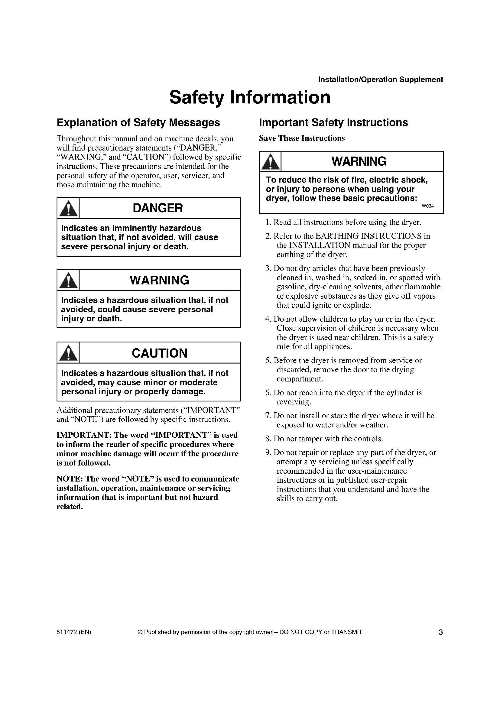
Safety Information
Explanation of Safety Messages
Throughout this manual and on machine decals, you will find precautionary statements (“DANGER,” “WARNING,” and “CAUTION”) followed by specific instructions. These precautions are intended for the personal safety of the operator, user, servicer, and those maintaining the machine.

DANGER
Indicates an imminently hazardous situation that, if not avoided, will cause severe personal injury or death.

WARNING
Indicates a hazardous situation that, if not avoided, could cause severe personal injury or death.

CAUTION
Indicates a hazardous situation that, if not avoided, may cause minor or moderate personal injury or property damage.
Additional precautionary statements (“IMPORTANT” and “NOTE”) are followed by specific instructions.
IMPORTANT: The word “IMPORTANT” is used to inform the reader of specific procedures where minor machine damage will occur if the procedure is not followed.
NOTE: The word “NOTE” is used to communicate installation, operation, maintenance or servicing information that is important but not hazard related.
Important Safety Instructions
Save These Instructions

WARNING
To reduce the risk of fire, electric shock, or injury to persons when using your dryer, follow these basic precautions:
W034
- Read all instructions before using the dryer.
- Refer to the EARTHING INSTRUCTIONS in the INSTALLATION manual for the proper earthing of the dryer.
- Do not dry articles that have been previously cleaned in, washed in, soaked in, or spotted with gasoline, dry-cleaning solvents, other flammable or explosive substances as they give off vapors that could ignite or explode.
- Do not allow children to play on or in the dryer. Close supervision of children is necessary when the dryer is used near children. This is a safety rule for all appliances.
- Before the dryer is removed from service or discarded, remove the door to the drying compartment.
- Do not reach into the dryer if the cylinder is revolving.
- Do not install or store the dryer where it will be exposed to water and/or weather.
- Do not tamper with the controls.
- Do not repair or replace any part of the dryer, or attempt any servicing unless specifically recommended in the user-maintenance instructions or in published user-repair instructions that you understand and have the skills to carry out.
Installation/Operation Supplement
- Do not use fabric softeners or products to eliminate static unless recommended by the manufacturer of the fabric softener or product.
- To reduce the risk of fire, DO NOT DRY plastics or articles containing foam rubber or similarly textured rubberlike materials.
- ALWAYS clean the lint filter after every load. A layer of lint in the filter reduces drying efficiency and prolongs drying time.
- Keep area around the exhaust opening and adjacent surrounding area free from the accumulation of lint, dust and dirt.
- The interior of the dryer and the exhaust duct should be cleaned periodically by qualified service personnel.
- If not installed, operated and maintained in accordance with the manufacturer's instructions or if there is damage to or mishandling of this product's components, use of this product could expose you to substances in the fuel or from fuel combustion which can cause death or serious illness and which are known to the State of California to cause cancer, birth defects or other reproductive harm.
- Dryer will not operate with the loading door open. DO NOT bypass the door safety switch by permitting the dryer to operate with the door open. The dryer will stop tumbling when the door is opened. Do not use the dryer if it does not stop tumbling when the door is opened or starts tumbling without pressing the START mechanism. Remove the dryer from use and call the service person.
- Do not put articles soiled with vegetable or cooking oil in the dryer, as these oils may not be removed during washing. Due to the remaining oil, the fabric may catch on fire by itself.
- To reduce the risk of fire, DO NOT put clothes which have traces of any flammable substances such as machine oil, flammable chemicals, thinner, etc., or anything containing wax or chemicals such as in mops and cleaning cloths, or anything dry-cleaned at home with a dry-cleaning solvent in the dryer.
- Use the dryer only for its intended purpose, drying clothes.
-
Always disconnect the electrical power to the dryer before attempting service. Disconnect the power cord by grasping the plug, not the cord.
-
If supply cord is damaged, it must be replaced by a special cord or assembly available from the manufacturer or its service agent.
- Install this dryer according to the INSTALLATION INSTRUCTIONS. All connections for electrical power, grounding and gas supply must comply with local codes and be made by licensed personnel when required. Do not do it yourself unless you know how!
- Remove laundry immediately after the dryer stops.
- Always read and follow manufacturer's instructions on packages of laundry and cleaning aids. Heed all warnings or precautions. To reduce the risk of poisoning or chemical burns, keep them out of reach of children at all times (preferably in a locked cabinet).
- Do not tumble fiberglass curtains and draperies unless the label says it can be done. If they are dried, wipe out the cylinder with a damp cloth to remove particles of fiberglass.
- ALWAYS follow the fabric care instructions supplied by the garment manufacturer.
- Never operate the dryer with any guards and/or panels removed.
- DO NOT operate the dryer with missing or broken parts.
- DO NOT bypass any safety devices.
- Failure to install, maintain, and/or operate this machine according to the manufacturer's instructions may result in conditions which can produce bodily injury and/or property damage.
IMPORTANT: Solvent vapors from dry-cleaning machines create acids when drawn through the heater of the drying unit. These acids are corrosive to the dryer as well as to the laundry load being dried. Be sure make-up air is free of solvent vapors.
IMPORTANT: Have your dryer installed properly. Don't do it yourself unless you know how!
NOTE: The WARNINGS and IMPORTANT SAFETY INSTRUCTIONS appearing in this manual are not meant to cover all possible conditions and situations that may occur. Common sense, caution and care must be exercised when installing, maintaining, or operating the dryer.
Always contact your dealer, distributor, service agent or the manufacturer about any problems or conditions you do not understand.
Installation
Dimensions and Specifications
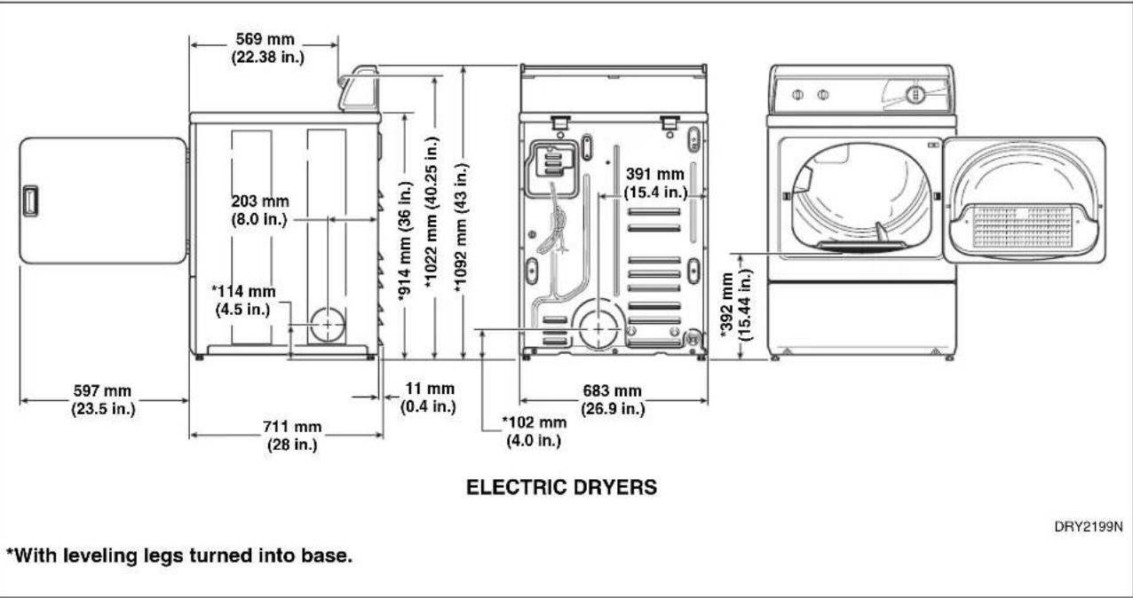
text_image
569 mm (22.38 in.) 203 mm (8.0 in.) *114 mm (4.5 in.) 597 mm (23.5 in.) 711 mm (28 in.) 11 mm (0.4 in.) *914 mm (36 in.) *1022 mm (40.25 in.) *1092 mm (43 in.) 391 mm (15.4 in.) 683 mm (26.9 in.) *392 mm (15.44 in.) ELECTRIC DRYERS DRY2199N *With leveling legs turned into base.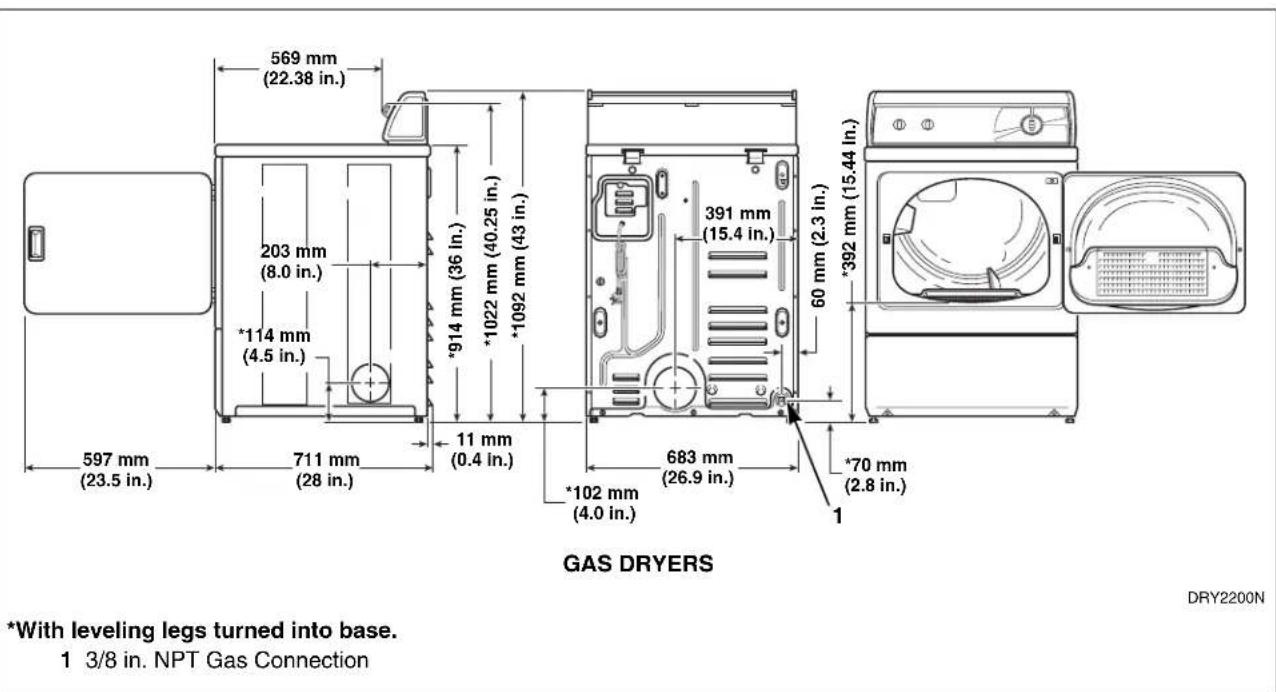
text_image
569 mm (22.38 in.) 203 mm (8.0 in.) *114 mm (4.5 in.) 597 mm (23.5 in.) 711 mm (28 in.) 11 mm (0.4 in.) *914 mm (36 in.) *1022 mm (40.25 in.) *1092 mm (43 in.) 391 mm (15.4 in.) 683 mm (26.9 in.) *102 mm (4.0 in.) *392 mm (15.44 in.) *70 mm (2.8 in.) GAS DRYERS DRY2200N *With leveling legs turned into base. 1 3/8 in. NPT Gas ConnectionInstallation/Operation Supplement
Installing the Dryer
NOTE: This manual is only a supplement. Refer to installation/operation manual for full instructions.
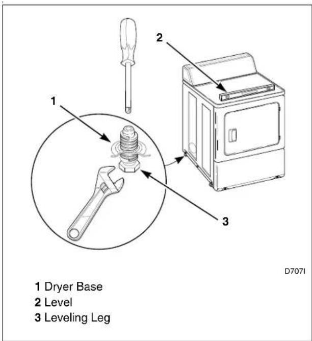
Step 1: Position and Level the Dryer
text_image
1 Dryer Base 2 Level 3 Leveling Leg D7071Figure 1
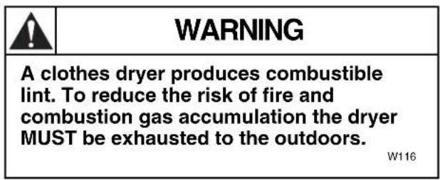
Step 2: Connect Dryer Exhaust System
text_image
WARNING A clothes dryer produces combustible lint. To reduce the risk of fire and combustion gas accumulation the dryer MUST be exhausted to the outdoors. W116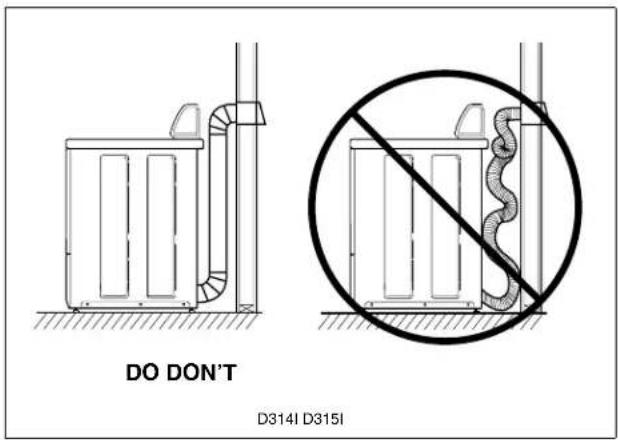
text_image
DO DON'T D314I D315IFigure 2
Step 3: Connect Gas Supply Pipe (Gas Dryer Only)
For further assistance, refer to section on Gas Requirements.
-
Make certain your dryer is equipped for use with the type of gas in your laundry room.
-
Remove the shipping cap from the gas connection at the rear of the dryer.
-
Connect to gas supply pipe.
-
Tighten all connections securely.
-
For L.P. (Liquefied Petroleum) gas connection, refer to section on Gas Requirements.
text_image
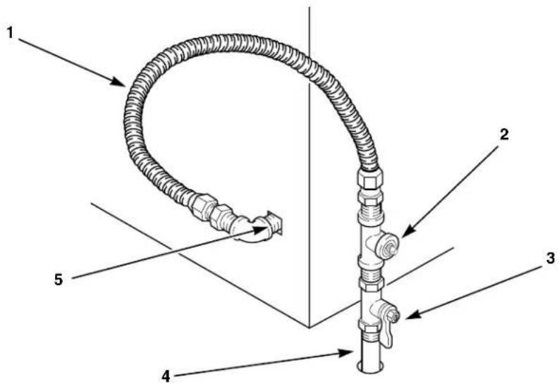
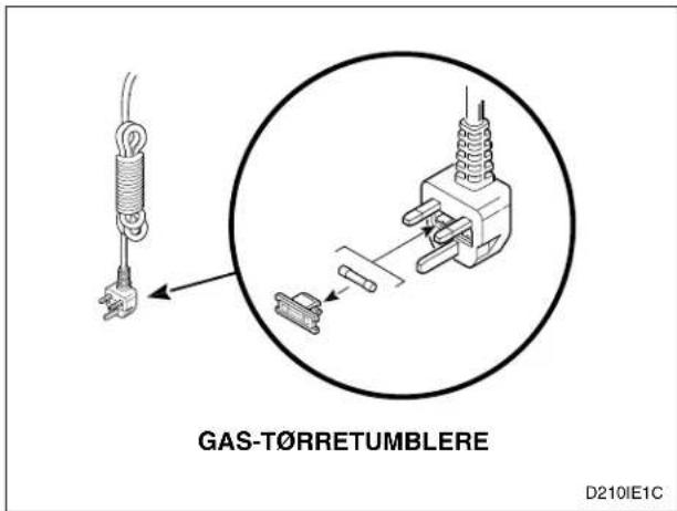
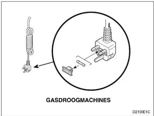
Technical diagram of a coiled hose assembly with numbered parts labeled 1 to 5D2331
1 New Stainless Steel Flexible Connector – Use only if allowed by local codes (Use Design CSA Certified Connector)
2 1/8 in. NPT Pipe Plug (For checking inlet gas pressure)
3 Equipment Shut-Off Valve – Installed within 1.8 m (6 ft.) of dryer
4 Black Iron Pipe Shorter than 6.1 m (20 ft.) – Use 9.5 mm (3/8 in.) pipe Longer than 6.1 m (20 ft.) – Use 12.7 mm (1/2 in.) pipe
5 3/8 in. NPT Gas Connection
Figure 3
Installation/Operation Supplement
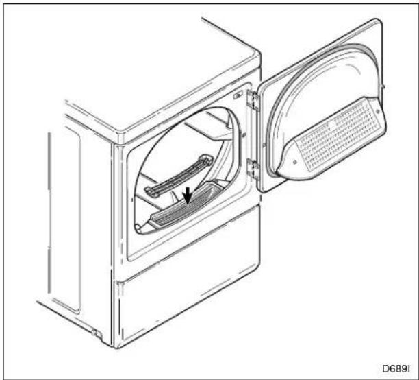
Step 4: Wipe Out Inside of Dryer
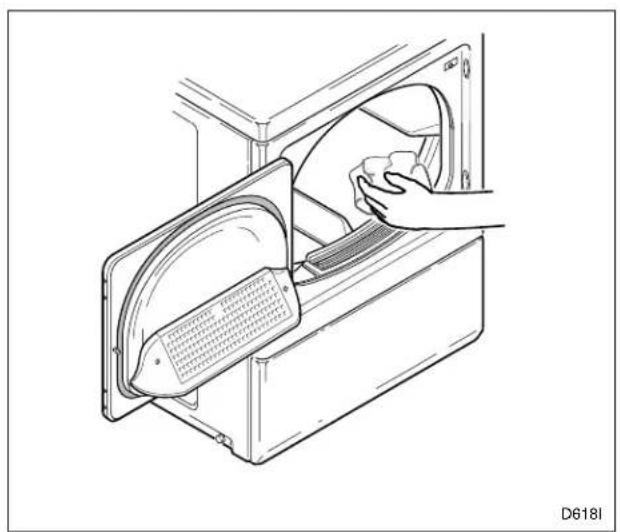
natural_image
Technical line drawing of a door handle assembly with a hand holding a component (no text or symbols)Figure 4
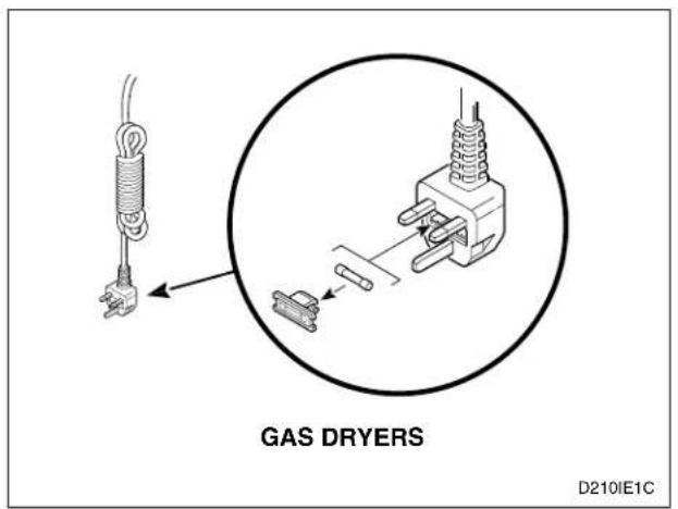
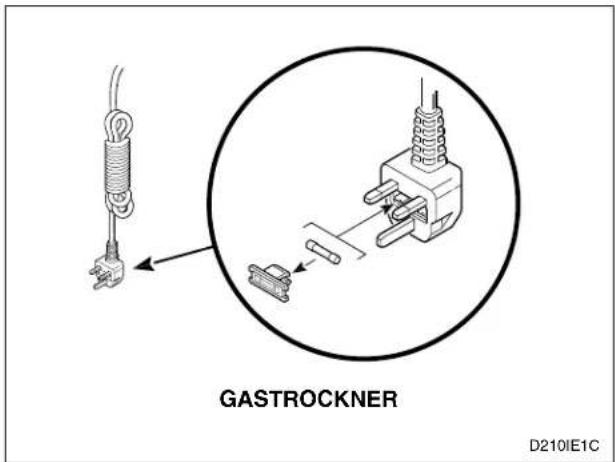
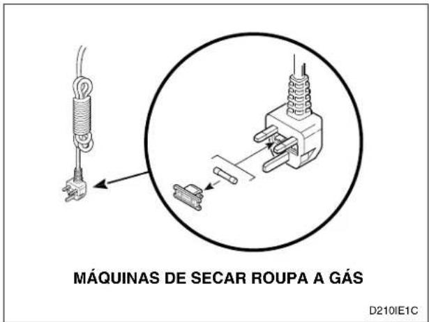
text_image
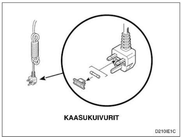
GAS DRYERS D210IE1CFigure 6
Step 6: Check Installation
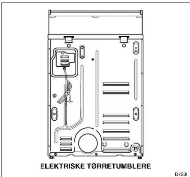
Step 5: Connect the Dryer to Electrical Power
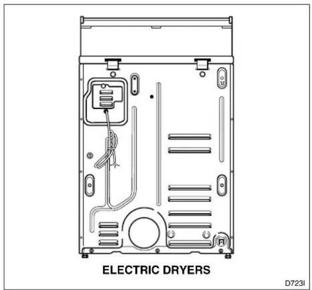
text_image
ELECTRIC DRYERS D7231Figure 5
Heat Source Check
NOTE: This manual is only a supplement. Refer to installation/operation manual for full instructions.
Electric Dryers
Close the loading door and start the dryer in a heat setting (refer to Operation section). After the dryer has operated for three minutes, the exhaust air or exhaust pipe should be warm.
Gas Dryers
IMPORTANT: This operation is to be conducted by qualified personnel only.

WARNING
To reduce the risk of serious injury or death, the lower front panel must be in place during normal operation.
W158
Electrical Requirements
NOTE: This manual is only a supplement. Refer to installation/operation manual for full instructions.
Electric Dryers
Refer to serial plate for requirements.
SINGLE-PHASE MODELS
(230 Volt, 50 Hertz, 2 Wire Plus Earth, 30 Amp Installation)
THREE-PHASE MODELS
(400/240 Volt, 50 Hertz, 4 Wire Plus Earth, 10 Amp Installation)
NOTE: Refer to Kit 756P3 for Delta to Wye conversion instructions.

WARNING
To reduce the risk of fire, electric shock, severe personal injury or death, all wiring and earthing MUST abide with local electrical codes. It is the customer's responsibility to have the wiring and fuses checked by a qualified electrician to make sure the laundry room has adequate electrical power to operate the dryer.
W458
Installation/Operation Supplement
To attach customer-supplied three-phase power cord (400 Volt WYE):
- Remove electrical access panel on rear of machine.
- Attach power cord wires as shown in Figure 7.
- Attach strain relief, supplied with machine, to power cord in accordance with all local codes and ordinances.
- Reinstall access panel.
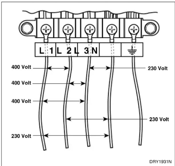
text_image
L 1 L 2 L 3 N 400 Volt 400 Volt 400 Volt 230 Volt 230 Volt DRY1931NFigure 7
Grounding and Wiring Instructions
The dryer must be connected to an earthed metal, permanent wiring system; or an equipment-earthing conductor must be run with the circuit conductors and connected to the equipment-earthing terminal or lead on the dryer.
NOTE: Electrical receptacle must be located so that it is easily accessible with machine in place. If machine is hard wired, an intermediate shut-off box with a 3 mm gap is required [335-1 (22.2)].
Gas Dryers
NOTE: This manual is only a supplement. Refer to installation/operation manual for full instructions.
(230 Volt, 50 Hertz, 2 Wire Plus Earth, 10 Amp Installation)

WARNING
To reduce the risk of fire, electric shock, severe personal injury or death, the electrical service to a gas dryer must abide with local electrical codes. The gas service to a gas dryer must conform with the local codes and ordinances, or in the absence of local codes and ordinances, with the latest edition of the National Fuel Gas Code ANSI Z223.1.
W238
The dryer is designed to be operated on a two-wire plus earth, 230 Volt, 50 Hertz, single-phase supply circuit fused at amperage found on serial plate.
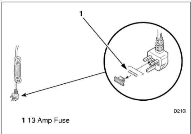
text_image
1 13 Amp Fuse D210IFigure 8
NOTE: Electrical receptacle must be located so that it is easily accessible with machine in place.
Gas Requirements
NOTE: This manual is only a supplement. Refer to installation/operation manual for full instructions.
Gas Dryers
(6.2 kW)
Gas Rate = 0.55 m ^3 /hr
NOTE: This appliance must be installed in accordance with regulations in force.
NOTE: This machine is supplied from the factory for operation on Natural Gas [2nd Family, Group H (E)] at nominal inlet pressure of 20 mbar for use in the countries of GB/IE/PT/ES/IT. For installation in other EU Countries, and/or for conversion to L.P. (Liquefied Petroleum) gas, consult the distributor. DO NOT connect the dryer to L.P. gas without consulting the distributor and/or without performing the proper conversion according to the conversion instructions (Conversion Kit 599P3).
| Natural Gas Altitude Adjustments | |||||
| Altitude Orifice Size | Part No. m m | ||||
| m | f | t | . | # | |
| 915 30 | 00 43 2.26 | 0.0890 | 503778 | ||
| 1830 | 6000 44 | 2.18 0 | 0860 587 | 19 | |
| 2440 | 8000 45 | 2.08 0 | 0820 503 | 779 | |
| 2740 | 9000 46 | 2.06 0 | 0810 503 | 780 | |
| 3050 | 10,000 | 47 1. | 99 0.0785 | 503781 | |
Table 1
The unit must be isolated from the gas supply piping system by closing the equipment shut-off valve during any pressure testing of the gas supply piping system at test pressures equal to or less than 50 mbar.

WARNING
To reduce the risk of gas leaks, fire or explosion:
- The dryer must be connected to the type of gas as shown on nameplate located in the door recess.
- Use a new flexible stainless steel connector.
- Use pipe joint compound insoluble in L.P. (Liquefied Petroleum) Gas, or Teflon tape, on all pipe threads.
- Purge air and sediment from gas supply line before connecting it to the dryer. Before tightening the connection, purge remaining air from gas line to dryer until odor of gas is detected. This step is required to prevent gas valve contamination.
- Do not use an open flame to check for gas leaks. Use a non-corrosive leak detection fluid.
- Any disassembly requiring the use of tools must be performed by a suitably qualified service person.
W316
Location Requirements
NOTE: This manual is only a supplement. Refer to installation/operation manual for full instructions.
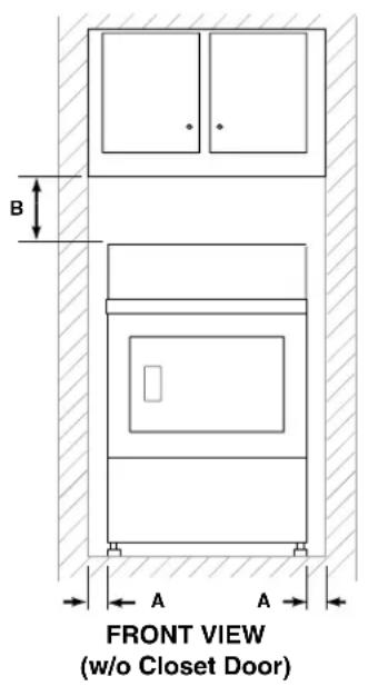
text_image
B A A FRONT VIEW (w/o Closet Door)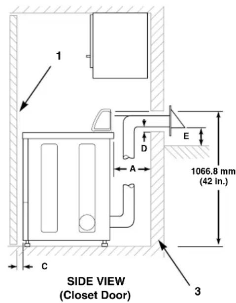
text_image
1 D E A 1066.8 mm (42 In.) SIDE VIEW (Closet Door) C 3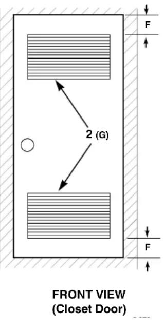
text_image
2 (G) FRONT VIEW (Closet Door)| Area Free | Standing/Alcove Installation Closet Installation | |
| A 0 mm (0 in.) minimum 0 mm (0 in.) minimum | ||
| B 304.8 mm (12 in.) minimum 304.8 mm (12 in.) minimum | ||
| C Not Applicable 50.8 mm (2 in.) minimum | ||
| D 50.8 mm (2 in.) minimum 50.8 mm (2 in.) minimum | ||
| E 304.8 mm (12 in.) minimum 304.8 mm (12 in.) minimum | ||
| F Not Applicable 76.2 mm (3 in.) | ||
| G Not Applicable 1016 mm | ^2 /open ( 40 in ^2 ) | |
1 Closet Door 3 Outer Wall of Enclosure
2 Centered Air Openings
(2 openings minimum)
Figure 9
Dryer Exhaust Requirements
NOTE: This manual is only a supplement. Refer to installation/operation manual for full instructions.

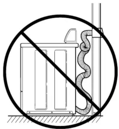
WARNING
A clothes dryer produces combustible lint. To reduce the risk of fire and combustion gas accumulation the dryer MUST be exhausted to the outdoors.
W116
This gas appliance contains or produces a chemical or chemicals which can cause death or serious illness and which are known to the State of California to cause cancer, birth defects, or other reproductive harm. To reduce the risk from substances in the fuel or from fuel combustion, make sure this appliance is installed, operated, and maintained according to the instructions in this manual.
W115
To reduce the risk of fire and the accumulation of combustion gases, DO NOT exhaust dryer air into a window well, gas vent, chimney or enclosed, unventilated area, such as an attic, wall, ceiling, crawl space under a building or concealed space of a building.
W045
To reduce the risk of fire, DO NOT use plastic or thin foil ducting to exhaust the dryer.
W354
IMPORTANT: Failure to exhaust dryer properly will void warranty.
Exhaust System Materials
NOTE: Venting materials are not supplied with the dryer (obtain locally).
Rigid metal duct is recommended. Non-combustible flexible metal duct is acceptable.
Make-Up Air Requirements
A dryer exhausts 85 liters/second (180 cfm) (measured at back of dryer) and sufficient make-up air must be supplied to replace air exhausted by each dryer.
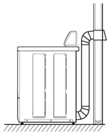
natural_image
Technical line drawing of a mechanical or electrical enclosure with pipes and a vertical support (no text or symbols)DO DON'T

natural_image
Diagram of a utility box with a diagonal line indicating no protection, showing no text or symbols.D314I D315I
Figure 10
Installation/Operation Supplement
Exhaust Direction
The dryer can be exhausted to the outdoors through the back, left, right or bottom of the dryer. EXCEPTION: Gas dryers cannot be vented out the left side because of the burner housing.
| Number of 90° Elbows | Weather Hood Type | |
| Recommended Use Only for | Short Run Installations | |
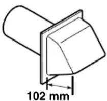 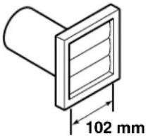 (4 in.) (4 in.)D673I (4 in.) (4 in.)D673I | 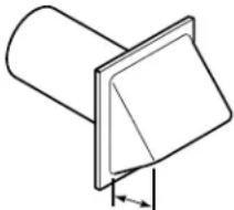 64 mm'(2-1/2 in.) D802I 64 mm'(2-1/2 in.) D802I | |
| Maximum length of 102 mm (4 in.) diameter rigid metal duct | ||
| 0 19.8 m (65 ft.) 16.8 m (55 ft.) | ||
| 1 16.8 m (55 ft.) 14.3 m (47 ft.) | ||
| 2 14.3 m (47 ft.) 12.5 m (41 ft.) | ||
| 3 11.0 m (36 ft.) 9.1 m (30 ft.) | ||
| 4 8.5 m (28 ft.) 6.7 m (22 ft.) | ||
| Maximum length of 102 mm (4 in.) diameter flexible metal duct | ||
| 0 13.7 m (45 ft.) 10.7 m (35 ft.) | ||
| 1 10.7 m (35 ft.) 8.2 m (27 ft.) | ||
| 2 9.1 m (30 ft.) 6.4 m (21 ft.) | ||
| 3 7.6 m (25 ft.) 5.2 m (17 ft.) | ||
| 4 6.1 m (20 ft.) 4.5 m (15 ft.) | ||
| NOTE: Deduct 1.8 m (6 ft.) for each additional elbow. | ||
Table 2
Dryer Airflow
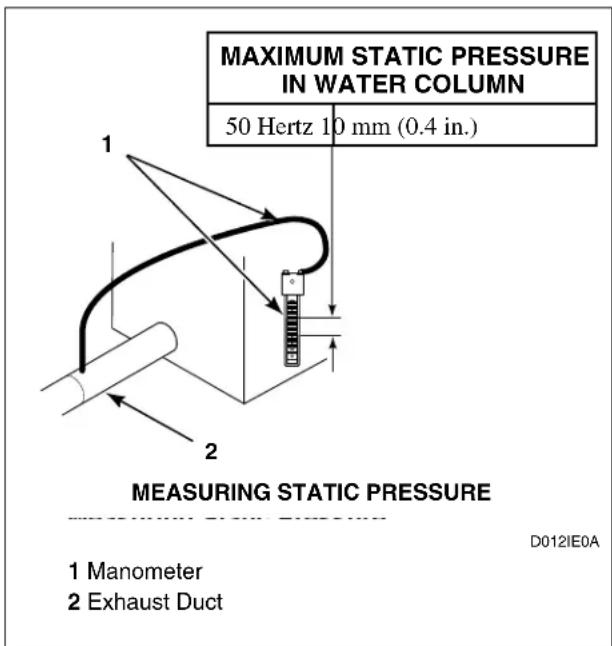
text_image
MAXIMUM STATIC PRESSURE IN WATER COLUMN 50 Hertz 10 mm (0.4 in.) 1 2 MEASURING STATIC PRESSURE D012IE0A 1 Manometer 2 Exhaust DuctFigure 11
Installation/Operation Supplement
Operation
Operation Instructions
NOTE: This manual is only a supplement. Refer to installation/operation manual for full instructions.
Step 1: Clean Lint Filter

natural_image
Technical line drawing of a mechanical device with an open lid and internal component (no text or symbols)Figure 12
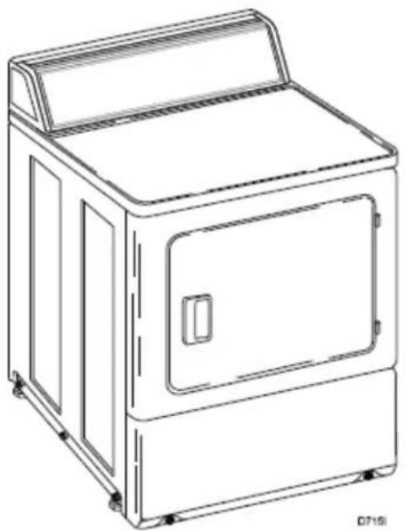
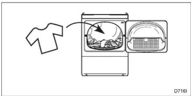
Step 2: Load Laundry
Load dryer half full with laundry (7.8 kg maximum dry clothes load).
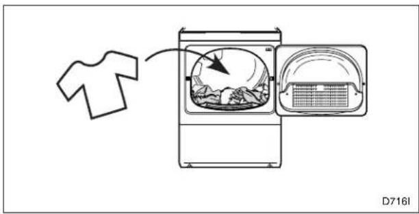
text_image
D716IFigure 13
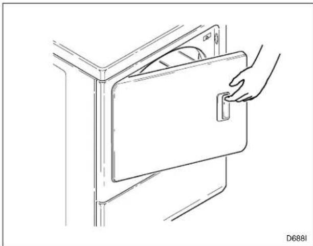
Step 3: Close Loading Door
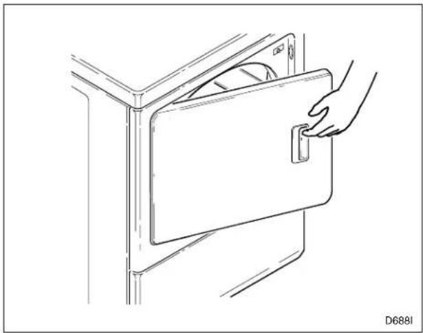
natural_image
Line drawing of a hand inserting a door into a cabinet (no text or symbols)Figure 14
Step 4: Select Temperature Setting
 DRY472N DRY472N | No Heat |
| [2T73]DRY473N | Medium Temperature/Delicates |
 DRY474N DRY474N | High Temperature/Regular – Permanent Press |
Step 5: Set Timer Knob
Select Fabric/Temperature setting.
 | DRY477N | Permanent Press |
 | DRY481N | Normal |
 | DRY484N | Delicates |
 | DRY485N | Time Dry |
 | DRY478N | Heat |
 | DRY479N | No Heat |
| [4337] | DRY482N | Less Dry |
| [4720] | DRY483N | More Dry |
Step 7: Remove Laundry
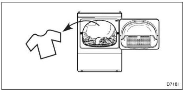
text_image
D718IFigure 16
End of Cycle Signal
| DRY475N | Sound Level |
| DRY476N | Sound Range (Low to High) |
Step 6: Start Dryer
Press timer knob to start dryer.
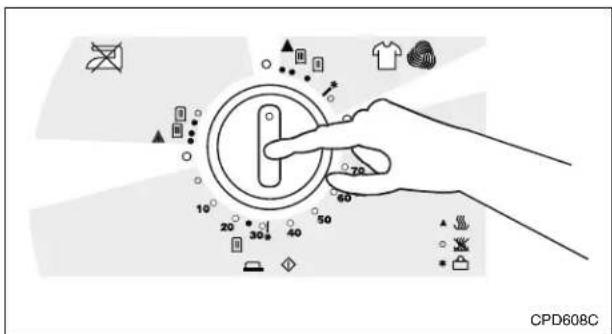
text_image
CPD608CFigure 15
Installation/Operation Supplement
Disposal of Unit
This appliance is marked according to the European directive 2002/96/EC on Waste Electrical and Electronic Equipment (WEEE).
This symbol on the product or on its packaging indicates that this product shall not be treated as household waste. Refer to Figure 17. Instead it shall be handed over to the applicable collection point for the recycling of electrical and electronic equipment. Ensuring this product is disposed of correctly will help prevent potential negative consequences for the environment and human health which could otherwise be caused by inappropriate waste handling of this product. The recycling of materials will help to conserve natural resources. For more detailed information about recycling of this product, please contact the local city office, household waste disposal service, or the source from which the product was purchased.
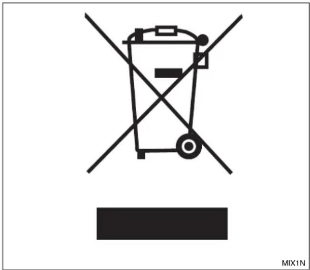
text_image
MIX1NFigure 17
Secadoras de ropa
natural_image
Line drawing of a simple kitchen appliance with a lid and front panel (no text or symbols)Paso 7: Retire la colada.... 19
© Published by permission of the copyright owner.
text_image
Technical diagram of a coiled hose assembly with numbered parts labeled 1 to 5D2331
natural_image
Technical line drawing of a door handle assembly with a hand cleaning the panel (no text or symbols)Figura 4

text_image
SECADORAS DE GAS D210IE1Cnatural_image
Technical line drawing of a mechanical or electrical enclosure with a vertical pipe and two rectangular components (no text or symbols)HAGA NO HAGA

natural_image
Diagram of a utility box with a hose and diagonal line indicating no signage or text (no readable text or symbols)D314I D315I
Figura 10
natural_image
Technical line drawing of a mechanical device with an open lid and internal components, showing no text or symbols.Figura 12
Paso 2: Introduzca la colada
natural_image
Line drawing of a hand inserting a rectangular device into a vertical panel (no text or symbols)Figura 14
Paso 7: Retire la colada

text_image
D718IFigura 16
natural_image
Line drawing of a simple kitchen appliance with a lid and front panel (no text or symbols)© Published by permission of the copyright owner.
Sécurité
natural_image
Line drawing of a hand cleaning a microwave oven with a grating (no text or symbols)Figure 4

text_image
SÈCHE-LINGE À GAZ D210IE1Cnatural_image
Technical line drawing of a mechanical or electrical enclosure with pipes and structural supports (no text or symbols)natural_image
Diagram of a utility vehicle with a diagonal line indicating no signage or restrictions, featuring a coiled hose and adjacent vehicle (no text or symbols present)D314I D315I
Figure 10
natural_image
Technical line drawing of a mechanical device with an open lid and internal components, showing no text or symbols.Figure 12
natural_image
Line drawing of a hand inserting a door into a cabinet (no text or symbols)Figure 14
natural_image
Line drawing of a simple kitchen appliance with a lid and front panel (no text or symbols)© Published by permission of the copyright owner.
text_image
Technical diagram of a coiled hose assembly with numbered parts labeled 1 to 5D2331
natural_image
Line drawing of a hand cleaning a microwave oven with a grating (no text or symbols)Abbildung 4
natural_image
Technical line drawing of a mechanical or electrical enclosure with pipes and a vertical support (no text or symbols)RICHTIG FALSCH
natural_image
Diagram of a utility vehicle with a diagonal line indicating no signage or restrictions, featuring a coiled hose and adjacent equipment (no text or symbols present)D314I D315I
Abbildung 10
Abluftrichtung
natural_image
Technical line drawing of a mechanical device with an open lid and internal components (no text or symbols)Abbildung 12
natural_image
Line drawing of a hand inserting a door into a cabinet (no text or symbols)Abbildung 14
natural_image
Line drawing of a washing machine with a lid and front panel, no text or symbols presentOpbevar disse instruktioner til fremtidig reference.
© Published by permission of the copyright owner.
text_image
Technical diagram of a coiled hose assembly with numbered parts labeled 1 to 5D2331
natural_image
Line drawing of a hand cleaning a microwave oven with a grating (no text or symbols)Figur 4
text_image
GAS-T∅RRETUMBLERE D210IE1CFigur 6
Punkt 6: Kontrollér installationen
Punkt 5: Tilslut tørretumbleren til elektricitet
text_image
ELEKTRISKE T∅RRETUMBLERE D7231Figur 5
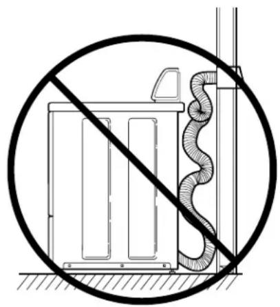
For at reducere risikoen for gasudslip, brand eller eksplosion:
natural_image
Technical line drawing of a mechanical or electrical enclosure with vertical supports and a curved duct (no text or symbols)ANBEFALET IKKE ANBEFALET

natural_image
Diagram of a utility vehicle with a diagonal line indicating no signage or restrictions, featuring a coiled hose and adjacent equipment (no text or symbols present)D314I D315I
Figur 10
natural_image
Technical line drawing of a mechanical device with an open lid and internal components, showing no text or symbols.Figur 12
natural_image
Line drawing of a hand inserting a door into a cabinet (no text or symbols)Figur 14
Punkt 4: Vælg temperaturindstillingen
| [A2WA]DRY472N | Ingen varme |
 DRY473N DRY473N | Middel temperatur/fint |
| [2XTT]DRY474N | Høj temperatur/almindeligt – Strygefrit |
Punkt 5: Indstil timerknappen
natural_image
Line drawing of a simple kitchen appliance with a lid and front panel (no text or symbols)© Published by permission of the copyright owner.
text_image
Technical diagram of a coiled hose assembly with numbered parts labeled 1 to 5D2331
natural_image
Line drawing of a hand cleaning a microwave oven with a grating (no text or symbols)figuur 4
text_image
GASDROOGMACHINES D210IE1Cnatural_image
Technical line drawing of a mechanical or electrical enclosure with a vertical pipe and two rectangular components (no text or symbols)DOEN NIET DOEN

natural_image
Diagram of a utility box with a hose and diagonal line indicating no signage or text (no readable text or symbols)D314I D315I
figuur 10
Installatie-/bedieningsaanvulling
Uitlaatrichting
Stap 1: Plusfilter schoonmaken
natural_image
Technical line drawing of a mechanical device with an open lid and internal components, showing no text or symbols.figuur 12
Stap 2: Was laden
natural_image
Line drawing of a hand inserting a door into a cabinet (no text or symbols)figuur 14
natural_image
Line drawing of a simple kitchen appliance with a lid and front panel (no text or symbols)© Published by permission of the copyright owner.
text_image
Technical diagram of a coiled hose assembly with numbered parts labeled 1 to 5D2331
natural_image
Technical line drawing of a door handle assembly with a hand cleaning the panel (no text or symbols)Figura 4

text_image
ASCIUGATRICI A GAS D210IE1Cnatural_image
Technical line drawing of a mechanical or electrical enclosure with a curved duct and two vertical panels (no text or symbols)DA FARE DA NON FARE

natural_image
Diagram of a utility vehicle with a diagonal line indicating no signage or restrictions, featuring a coiled hose and adjacent vehicle (no text or symbols present)D314I D315I
Figura 10
natural_image
Technical line drawing of a mechanical device with an open lid and internal components (no text or symbols)Figura 12
natural_image
Line drawing of a hand inserting a door into a cabinet (no text or symbols)Figura 14
natural_image
Line drawing of a simple kitchen appliance with a lid and front panel (no text or symbols)© Published by permission of the copyright owner.
text_image
SIM NÃO D314I D315IFigura 2
text_image
Technical diagram of a coiled hose assembly with numbered parts labeled 1 to 5D2331
natural_image
Line drawing of a hand cleaning a microwave oven with a grating (no text or symbols)Figura 4
text_image
MÁQUINAS DE SECAR ROUPA A GÁS D210IE1Cnatural_image
Technical line drawing of a mechanical or electrical enclosure with a vertical pipe and two rectangular panels (no text or symbols)SIM NÃO

natural_image
Diagram of a utility box with a diagonal line and a coiled hose, enclosed in a circle (no text or symbols)D314I D315I
Figura 10
natural_image
Technical line drawing of a mechanical device with an open lid and internal components, showing no text or symbols.Figura 12
Passo 2: Colocar a roupa
Carregar a máquina até metade com roupa (carga máxima de 7,8 kg de roupa seca).
text_image
D716IFigura 13
Passo 3: Fechar a porta de carregamento
natural_image
Line drawing of a hand inserting a rectangular device into a vertical panel (no text or symbols)Figura 14
natural_image
Line drawing of a simple kitchen appliance with a lid and front panel (no text or symbols)© Published by permission of the copyright owner.
Säkerhetsinformation
text_image
Technical diagram of a coiled hose assembly with numbered parts labeled 1 to 5D2331
natural_image
Technical line drawing of a door handle assembly with a hand holding a component (no text or symbols)Figur 4

natural_image
Technical line drawing of a vertical industrial or utility structure with pipes and a central container (no text or symbols)RÄTT FEL

natural_image
Diagram of a utility box with a diagonal line and a coiled hose, enclosed in a circle (no text or symbols)D314I D315I
Figur 10
natural_image
Technical line drawing of a mechanical device with an open lid and internal components, showing no text or symbols.Figur 12
natural_image
Line drawing of a hand inserting a door into a cabinet (no text or symbols)Figur 14
Steg 4: Ställ in temperaturen
 DRY472N DRY472N | Ingen värme |
 DRY473N DRY473N | Medeltemperatur/Ömtåligt |
| [7XKT]DRY474N | Hög temperatur/Vanlig - Skrynkelfritt |
natural_image
Line drawing of a simple kitchen appliance with a lid and front panel (no text or symbols)© Published by permission of the copyright owner.
Turvallisuustiedot
text_image
Technical diagram of a coiled hose assembly with numbered parts labeled 1 to 5D2331
natural_image
Technical line drawing of a hand cleaning a device with a mesh cover (no text or symbols)Kuva 4
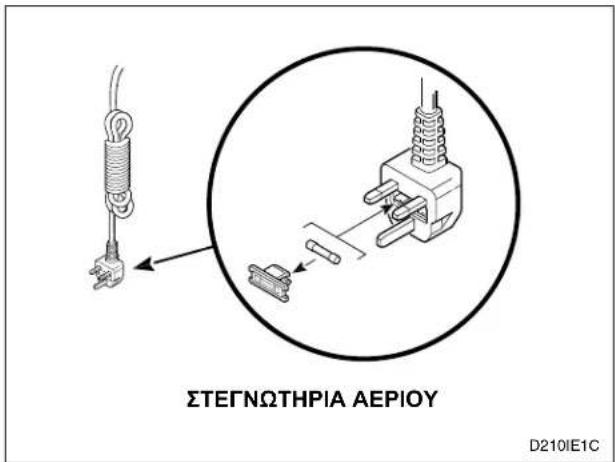
text_image
KAASUKUIVURIT D210IE1CYKSIVAIHEISET MALLIT
KOLMIVAIHEISET MALLIT
natural_image
Technical line drawing of a mechanical or electrical enclosure with a vertical pipe and two rectangular components (no text or symbols)TEE NÄIN EI NÄIN

natural_image
Diagram of a utility vehicle with a diagonal line indicating no signage or restrictions, featuring a coiled hose and adjacent equipment (no text or symbols present)D314I D315I
Kuva 10
Poiston suunta
natural_image
Technical line drawing of a mechanical device with an open lid and internal components, showing no text or symbols.Kuva 12
natural_image
Line drawing of a hand inserting a door into a cabinet (no text or symbols)Kuva 14
natural_image
Line drawing of a simple kitchen appliance with a lid and front panel (no text or symbols)© Published by permission of the copyright owner.
text_image
Technical diagram of a coiled hose assembly with numbered parts labeled 1 to 5D2331
natural_image
Line drawing of a hand cleaning a microwave oven with a grater inside (no text or symbols)Σχήμα 4
natural_image
Technical line drawing of a mechanical or electrical enclosure with vertical supports and a curved duct (no text or symbols)TI NA KANETE
natural_image
Diagram of a utility box with a diagonal line and a coiled hose, enclosed in a circle (no text or symbols)TI NA MHN KANETE
D314I D315I
Σχήμα 10
natural_image
Technical line drawing of a mechanical device with an open lid and internal components (no text or symbols)Σχήμα 12
natural_image
Line drawing of a hand inserting a door into a cabinet (no text or symbols)Σχήμα 14