
CRND - Hi-fi system SAMSON - Free user manual and instructions
Find the device manual for free CRND SAMSON in PDF.
| Product Type | UHF Receiver for Wireless Microphone System |
| Brand | Samson |
| Model | CRND |
| Series | Concert IV |
| Number of Channels | 1 fixed channel (factory preset) |
| Reception Technology | Non Diversity (single antenna) |
| Operating Frequency | UHF Band |
| Power Supply | 9 V DC via included power adapter |
| Dimensions (W x D x H) | Approximately 200 x 150 x 45 mm (rack-mountable in 1U with optional adapter) |
| Weight | Approximately 0.5 kg |
| Audio Output | 1 x 6.35 mm unbalanced jack (high impedance, 5 kΩ) |
| Indicators | Power LED, TX ON LED, Peak LED |
| Controls | Volume, Squelch (reception threshold) |
| Antenna | Fixed antenna included, rear mounting possible (optional) |
| Maintenance and Cleaning | Clean with a dry, lint-free cloth. Do not use chemical products. |
| Safety | Use only the supplied power adapter. Do not expose to humidity. |
| Included Accessories | Power adapter, antenna, plastic screwdriver for adjustments |
| Repairability | Spare parts available from Samson technical service. Professional repair recommended. |
Frequently Asked Questions - CRND SAMSON
User questions about CRND SAMSON
0 question about this device. Answer the ones you know or ask your own.
Ask a new question about this device
Download the instructions for your Hi-fi system in PDF format for free! Find your manual CRND - SAMSON and take your electronic device back in hand. On this page are published all the documents necessary for the use of your device. CRND by SAMSON.
USER MANUAL CRND SAMSON
Guided Tour - CR4 Receiver 4
Guided Tour - CRND Receiver 5
Guided Tour - CT4L / CT4G Transmitter 6
Guided Tour - HT4 Transmitter 7
Setting Up and Using the Concert IV System 8
Appendix A: CT4L Multipin Wiring Guide and Chart 38
Specifications Inside Back Cover
FRANCAIS
Introduction 11
Specifications Inside Back Cover
DEUTSCHE
Einleitung 20
Produced by On The Right Wavelength for Samson Technologies Corp.
Copyright 1997, 1998, Samson Technologies Corp.
Printed January 1998
Samson Technologies Corp.
575 Underhill Blvd.
P.O.Box 9031
Syosset, NY 11791-9031
Phone: 1-800-3-SAMSON (1-800-372-6766)
Fax: 516-364-3888
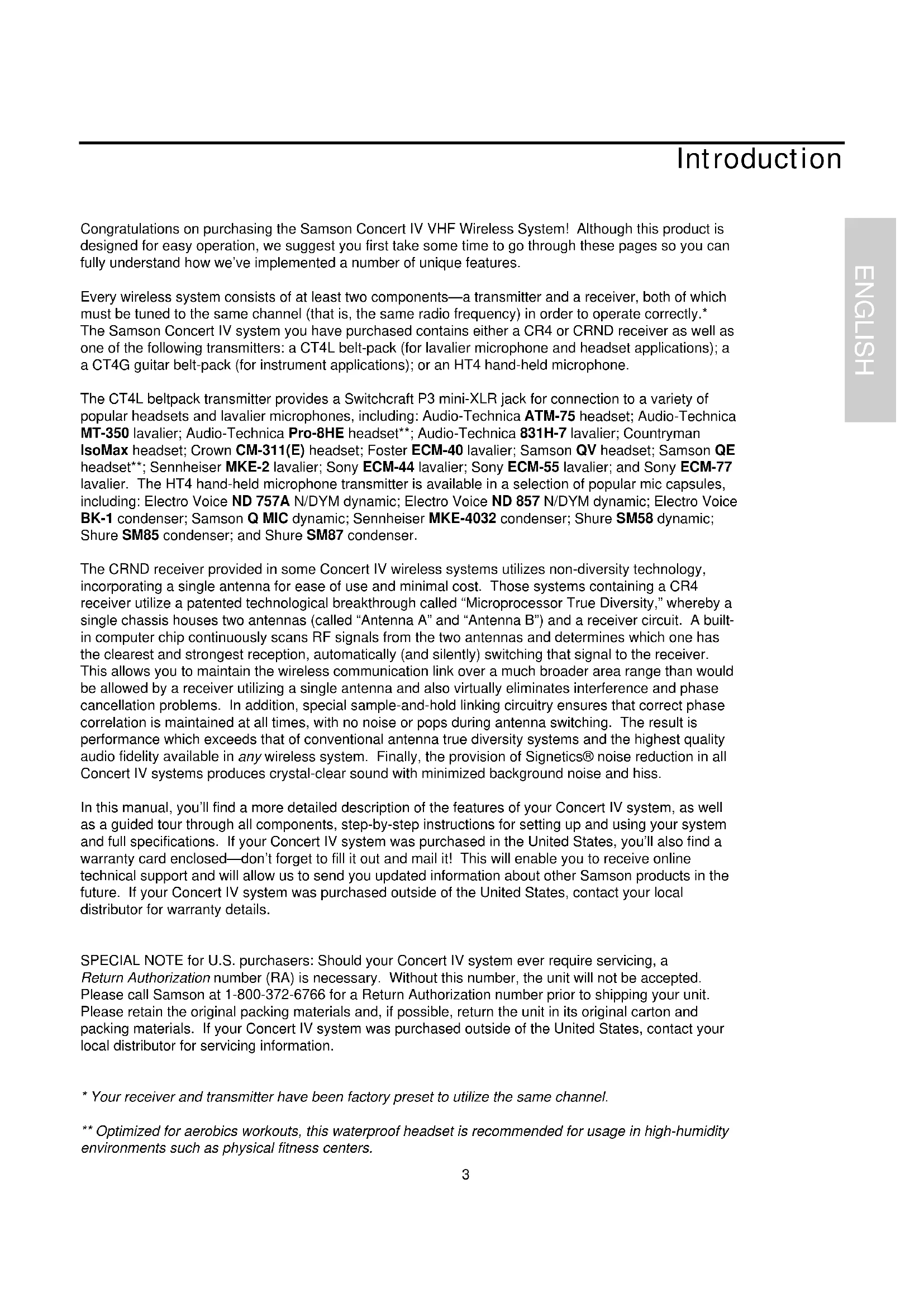
Congratulations on purchasing the Samson Concert IV VHF Wireless System! Although this product is designed for easy operation, we suggest you first take some time to go through these pages so you can fully understand how we've implemented a number of unique features.
Every wireless system consists of at least two components—a transmitter and a receiver, both of which must be tuned to the same channel (that is, the same radio frequency) in order to operate correctly.* The Samson Concert IV system you have purchased contains either a CR4 or CRND receiver as well as one of the following transmitters: a CT4L belt-pack (for lavalier microphone and headset applications); a a CT4G guitar belt-pack (for instrument applications); or an HT4 hand-held microphone.
The CT4L beltpack transmitter provides a Switchcraft P3 mini-XLR jack for connection to a variety of popular headsets and laveler microphones, including: Audio-Technica ATM-75 headset; Audio-Technica MT-350 laveler; Audio-Technica Pro-8HE headset**; Audio-Technica 831H-7 laveler; Countryman IsoMax headset; Crown CM-311(E) headset; Foster ECM-40 laveler; Samson QV headset; Samson QE headset**; Sennheiser MKE-2 laveler; Sony ECM-44 laveler; Sony ECM-55 laveler; and Sony ECM-77 laveler. The HT4 hand-held microphone transmitter is available in a selection of popular mic capsules, including: Electro Voice ND 757A N/DYM dynamic; Electro Voice ND 857 N/DYM dynamic; Electro Voice BK-1 condenser; Samson Q MIC dynamic; Sennheiser MKE-4032 condenser; Shure SM58 dynamic; Shure SM85 condenser; and Shure SM87 condenser.
The CRND receiver provided in some Concert IV wireless systems utilizes non-diversity technology, incorporating a single antenna for ease of use and minimal cost. Those systems containing a CR4 receiver utilize a patented technological breakthrough called "Microprocessor True Diversity," whereby a single chassis houses two antennas (called "Antenna A" and "Antenna B") and a receiver circuit. A built-in computer chip continuously scans RF signals from the two antennas and determines which one has the clearest and strongest reception, automatically (and silently) switching that signal to the receiver. This allows you to maintain the wireless communication link over a much broader area range than would be allowed by a receiver utilizing a single antenna and also virtually eliminates interference and phase cancellation problems. In addition, special sample-and-hold linking circuitry ensures that correct phase correlation is maintained at all times, with no noise or pops during antenna switching. The result is performance which exceeds that of conventional antenna true diversity systems and the highest quality audio fidelity available in any wireless system. Finally, the provision of Signetics® noise reduction in all Concert IV systems produces crystal-clear sound with minimized background noise and hiss.
In this manual, you'll find a more detailed description of the features of your Concert IV system, as well as a guided tour through all components, step-by-step instructions for setting up and using your system and full specifications. If your Concert IV system was purchased in the United States, you'll also find a warranty card enclosed—don't forget to fill it out and mail it! This will enable you to receive online technical support and will allow us to send you updated information about other Samson products in the future. If your Concert IV system was purchased outside of the United States, contact your local distributor for warranty details.
SPECIAL NOTE for U.S. purchasers: Should your Concert IV system ever require servicing, a Return Authorization number (RA) is necessary. Without this number, the unit will not be accepted. Please call Samson at 1-800-372-6766 for a Return Authorization number prior to shipping your unit. Please retain the original packing materials and, if possible, return the unit in its original carton and packing materials. If your Concert IV system was purchased outside of the United States, contact your local distributor for servicing information.
- Your receiver and transmitter have been factory preset to utilize the same channel.
** Optimized for aerobics workouts, this waterproof headset is recommended for usage in high-humidity environments such as physical fitness centers.
Guided Tour - CR4 Receiver
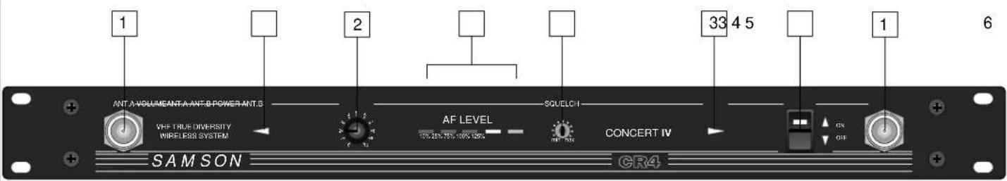
1: Antenna A and B mountings - Connect the supplied antennas to these mountings. Third-party receiver antennas should not be substituted—use only the antennas provided with the CR4. See the "Setting Up and Using the Concert IV System" section on page 6 for more about antenna installation and positioning.
2: Volume - This knob determines the level of the audio signal sent from both the balanced and unbalanced output jacks on the rear panel.
3: "A"/"B" LEDs - When signal is being received, one of these LEDs will be lit, showing you whether signal from either the "A" or "B" antenna is currently being used. A computer chip inside the CR4 constantly scans the two and automatically selects whichever is receiving the strongest, clearest signal. This "Microprocessor True Diversity" switching is completely inaudible, and it effectively increases overall range while reducing potential interference and phase cancellation problems.
4: AF Level meter - This "ladder" display (similar to the VU bar meter used on audio devices) indicates the strength of the incoming audio signal. When the 100% segment is lit, the incoming signal is optimized at unity gain; when the 125% segment is lit, the signal is overloading. When only the left-most 10% segment is lit, the incoming signal is at just 10% of optimum strength. If no segments are lit, little or no signal is being received. For more information, see the "Setting Up and Using the Concert IV System" section on page 6 in this manual.
5: Squelch control - This control determines the maximum range of the CR4 before audio signal dropout. It should normally be left at its factory setting. For more information, see the "Setting Up and Using the Concert IV System" section on page 6 in this manual.
6: Power switch - Use this to turn the main power on and off.
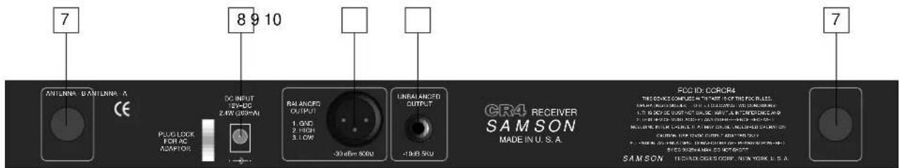
7: Rear-mount antenna knockouts - The CR4 antennas (normally mounted on the front panel) can optionally be mounted on these areas of the rear panel. Contact Samson or your local distributor for further information.
8: DC input - Connect the supplied AC adapter here. WARNING: Do not substitute any other kind of power adapter; doing so can cause severe damage to the unit and will void your warranty.
9: Balanced output - Use this electronically balanced low impedance (600 Ohm) XLR plug when connecting the CR4 to the microphone input of professional (-30 dBm) audio equipment, wired as follows: Pin 1 ground, Pin 2 high (hot), and Pin 3 low (cold).
10: Unbalanced output - Use this unbalanced high impedance (5K Ohm) 1/4" jack when connecting the CR4 to the microphone input of consumer (-10 dBv) audio equipment, wired as follows: tip hot, sleeve ground.
* If required, both the balanced and unbalanced outputs can be used simultaneously.
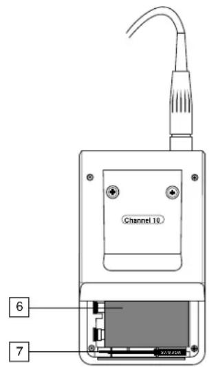
Guided Tour - CRND Receiver
1: Antenna mounting - Connect the supplied antenna to this mounting. Third-party receiver antennas should not be substituted—use only the antenna provided with the CRND. See the "Setting Up and Using the Concert IV System" section on page 6 for more about antenna installation and positioning.
2: "TX ON" LED - Lights when carrier signal of sufficient strength is being received by the CRND.
3: Squelch control - This control determines the maximum range of the CRND before audio signal dropout. It should normally be left at its factory setting. For more information, see the "Setting Up and Using the Concert IV System" section on page 6 in this manual.
4: Peak LED - This LED lights when output signal from the CRND is at the onset of clipping (that is, when it is on the verge of being distorted). If you see this light during operation, move the microphone further away or lower the output level of your instrument or transmitter. For more information, see the "Setting Up and Using the Concert IV System" section on page 6 in this manual.
5: Volume - This knob determines the level of the audio signal sent from the unbalanced output jack on the rear panel.
6: Power LED - Lights whenever the CRND is powered on.
7: DC input - Connect the supplied AC adapter here. WARNING: Do not substitute any other kind of power adapter; doing so can cause severe damage to the unit and will void your warranty.
8: Unbalanced output - Use this unbalanced high impedance (5K Ohm) 1/4" jack to connect the CRND to the microphone input of your mixer. The jack is wired as follows: tip hot, sleeve ground.
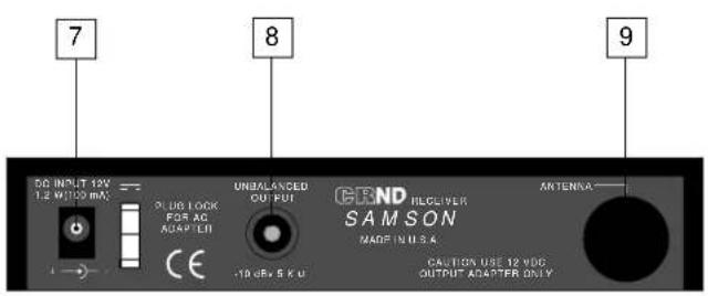
9: Rear-mount antenna knockout - The CRND antenna (normally mounted on the front panel) can optionally be mounted on this area of the rear panel. Contact Samson or your local distributor for further information.
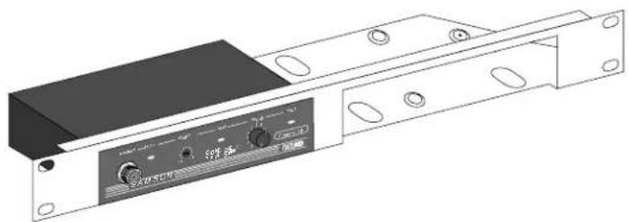
Rack-mounting the CRND
As shown in the illustration below, one or two CRND receivers can be mounted in a single 19" rack space with the use of an optional adapter available from Samson or your local distributor.
Guided Tour - CT4L / CT4G Beltpack Transmitter
1: Mute on-off switch - When set to the "Off" position, audio signal is transmitted. When set to the "On" position, the audio signal is muted. The advanced circuitry in the Concert IV system ensures that no "pop" or "thud" will be heard during muted. Note that turning this on does not turn off the CT4L / CT4G power—it is simply a way to temporarily mute the transmission of audio signal. If you don't plan on using the CT4L / CT4G for extended periods, turn off its power by using the power on-off switch (see #3 below).
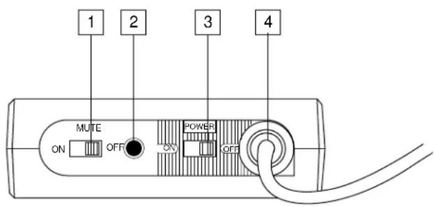
2: Battery LED - This LED is an indicator of battery strength. When the CT4L / CT4G is first powered on, this LED will light for about two-tenths of a second (if the battery is sufficiently strong), and will then go off. When battery voltage is low, this LED lights steadily, indicating that the battery needs to be replaced.
3: Power on-off switch - Use this to turn the CT4L / CT4G on or off (to conserve battery power, be sure to leave it off when not in use). WARNING: Be sure to mute the audio signal at your external mixer or amplifier before turning the CT4L / CT4G power on or off, or an audible pop may result.
4: Input connector - The input device is connected here. The CT4L is supplied with either a lavalier or headset microphone (connected via a Switchcraft mini-XLR plug, as shown in the illustration above), while the CT4G is supplied with a permanently connected 1/4" plug cable.
5: Battery door - Opening the CT4L / CT4G battery door must be done with care. See the "Setting Up and Using the Concert IV System" section on page 6 in this manual for more information.
6: Battery holder - Insert a standard 9-volt alkaline battery here, being sure to observe the plus and minus polarity markings shown. We recommend the Duracell MN 1604 type battery. Although rechargeable Ni-Cad batteries can be used, they do not supply adequate current for more than four hours. WARNING: Do not insert the battery backwards; doing so can cause severe damage to the CT4L / CT4G and will void your warranty.
7: Plastic screwdriver - Specially designed for use in adjusting the CT4L / CT4G Level control (see #8 below) and/or receiver Squelch control (see the "Guided Tour: CR4," "Guided Tour: CRND" and "Setting Up and Using the Concert IV System" sections on pages 2, 3 and 6 in this manual.
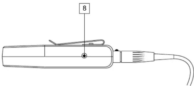
8: Audio Input Level control (trimpot) - This input sensitivity control has been factory preset to provide optimum level for the particular lavalier or headset model being used (in the case of the CT4G, it is preset for optimum instrument level) and so we recommend that this not be adjusted manually. If necessary, however, you can use the supplied plastic screwdriver to raise or lower the CT4L / CT4G input level. See the "Setting Up and Using the Concert IV System" section on page 6 in this manual for more information.
Guided Tour - HT4 Handheld Microphone Transmitter
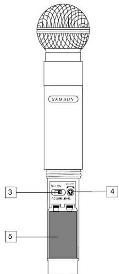
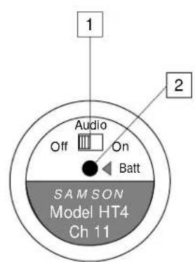
1: Audio on-off switch - When set to the "On" position, audio signal is transmitted. When set to the "Off" position, the audio signal is muted. The advanced circuitry in the Concert IV system ensures that no "pop" or "thud" will be heard during muting. Note that turning this off does not turn off the transmitter power—it is simply a way to temporarily mute the transmission of audio signal. If you don't plan on using the transmitter for extended periods, turn off the transmitter power by using the power on-off switch (see #3 below).
2: Battery LED - This LED is an indicator of battery strength. When the HT4 is first powered on, this LED will light for about two-tenth of a second (if the battery is sufficiently strong), and will then go off. When battery voltage is low, this LED lights steadily, indicating that the battery needs to be replaced.
3: Power on-off switch - Use this to turn the HT4 on or off (to conserve battery power, be sure to leave it off when not in use). WARNING: Be sure to mute the audio signal at your external mixer or amplifier before turning transmitter power on or off, or an audible pop may result.
4: Mic level control (trimpot) - Determines the overall output level of the HT4. Use the supplied plastic screwdriver to set this to the optimum microphone output level. See the "Setting Up and Using the Concert IV System" section on page 6 in this manual for more information.
5: Battery holder - Insert a standard alkaline 9-volt battery here, being sure to observe the plus and minus polarity markings shown. We recommend the Duracell MN 1604 type battery. Although rechargeable Ni-Cad batteries can be used, we do not recommend them as they do not supply adequate current for more than two hours. WARNING: Do not insert the battery backwards; doing so can cause severe damage to the HT4 and will void your warranty.
Setting Up and Using the Concert IV System
The basic procedure for setting up and using your Concert IV VHF Wireless System takes only a few minutes:
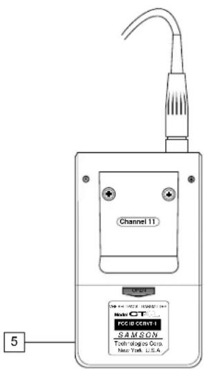
- For the Concert IV system to work correctly, both the receiver and transmitter must be set to the same channel. Remove all packing materials (save them in case of need for future service) and check to make sure that the enclosed receiver and transmitter are set to the same channel (this is listed on the front panel of the CR4 and CRND, on the belt clip of the CT4L and CT4G, and on the bottom of the HT4. If these channels do not match, contact Samson Technical Support at 1-800-372-6766.
- Mount the supplied antennas into your receiver (the CR4 has two antennas while the CRND has one) by inserting the M connector and turning the outer ring clockwise until snug. Start by placing one or both antennas in a vertical position; this will suffice for most environments. Insert the included Allen wrench into the front of each antenna and turn clockwise to lock it into position.
- Set the Power on-off switch in your CT4L / CT4G beltpack or HT4 handheld transmitter to "Off."
- If you are using a CT4L or CT4G transmitter, locate the Open arrow on the rear of its battery door and press down and forward (away from the belt clip), then lift up. The battery door is hinged and not intended to be removed from the transmitter case. Please use care when opening this door as undue force will destroy the hinge. If you are using an HT4 transmitter, unscrew the bottom section of the microphone by turning it counterclockwise and then slide it off.
- Place a fresh 9-volt alkaline battery in the transmitter battery holder, taking care to observe the polarity markings. If you are using a CT4L or CT4G transmitter, replace the battery door by swinging it down so that it is parallel with the rear panel and then gently pushing upward towards the belt clip. Whichever transmitter you are using, leave it switched off for the moment.
- Make the physical cable connection between the output of your receiver (if you have a CR4, you can use either or both of the balanced or unbalanced jacks) and the microphone level input of your amplifier or mixer. If you have a CR4 and are using professional (-30 dBm) equipment, the balanced jack is preferable since it will deliver an electromagnetically cleaner signal. Leave the amplifier (and/or mixer) off at this time.
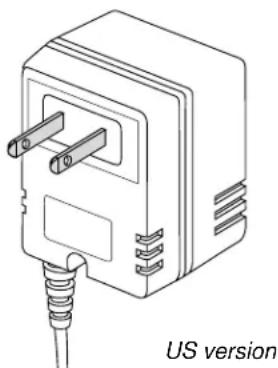
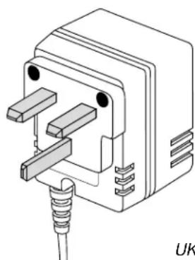
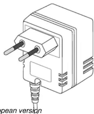
- Turn the Volume knob on the front panel of the receiver completely counterclockwise (to the "0" position). Connect the supplied AC adapter to the DC Input on the receiver's rear panel, using the plug lock, then plug the adapter into any standard AC outlet. If you have a CR4, press the front-panel power switch to turn the unit on. Note that the Samson CR4 / CRND AC adapter is available with three different plug types so it can be used in the United States, United Kingdom, or other European countries.
- Turn on the power to the CT4L, CT4G or HT4 transmitter (using its Power on-off switch); the "Battery" LED should briefly light if the battery is good. If you are using an HT4 transmitter, replace the bottom section of the microphone by sliding it on and then screwing it back on. Once the transmitter is powered on, either the "TX ON" LED (in the CRND) or either the "A" or "B" LED on the CR4 front panel will light (showing which antenna is receiving the stronger signal).
- Now it's time to set the audio levels. Turn on your connected amplifier and/or mixer but keep its volume all the way down. Next, make sure that your transmitter is unmuted, as follows:
Setting Up and Using the Concert IV System
- If you are using a CT4L or CT4G transmitter, set the Mute switch to "Off"
- If you are using an HT4 transmitter, set the Audio switch to "On"
IF YOUR SYSTEM HAS A CR4 RECEIVER, FOLLOW THE INSTRUCTIONS IN THIS PARAGRAP: If you are using the HT4 transmitter (or if you are using the CT4L transmitter with a connected lavalier microphone or headset), speak or sing into the mic at a normal performance level while observing the CR4 front panel AF Level meter. If you are using the CT4G transmitter with a connected instrument, play the instrument at normal performance level while observing the CR4 front panel AF Level meter. If the "100%" (unity gain) segment is lighting steadily, with just occasional higher excursions, the audio level is correctly set. If not, use the supplied plastic screwdriver to slowly adjust the HT4, CT4L, or CT4G Level control (trimpot) until the CR4 AF Level meter "100%" (unity gain) segment lights steadily (with occasional higher excursions). Then slowly raise the CR4 Volume knob to the 2 o'clock position (unity gain) and set the volume of your amplifier/mixer until the desired level is reached.
IF YOUR SYSTEM HAS A CRND RECEIVER, FOLLOW THE INSTRUCTIONS IN THIS PARAGRAPH. Begin by setting your amplifier/mixer to a low listening level. If you are using the HT4 transmitter (or if you are using the CT4L transmitter with a connected lavalier microphone or headset), speak or sing into the mic at a normal performance level while slowly raising the CRND front panel Volume knob to the 2 o'clock position (unity gain). If you are using the CT4G transmitter with a connected instrument, play the instrument at normal performance level while slowly raising the CRND front panel Volume knob to the 2 o'clock position. Finally, set the volume of your amplifier/mixer until the desired level is reached.
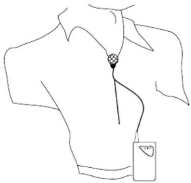
THIS PARAGRAPH AND ALL SUBSEQUENT ONES APPLY TO ALL CONCERT IV SYSTEMS. If you are using a CT4L beltpack transmitter equipped with a lavalier microphone, note that correct lavalier placement is critical to sound quality. We recommend that you place it as shown in this illustration—as close to your mouth as possible but off to one side (to minimize nasality) and unobstructed by clothing. Bear in mind also that omni microphones (mics which pick up signal from all directions) are more prone to feedback problems than unidirectional (cardioid or supercardioid) ones; in general, you can avoid feedback by taking care not to use any microphone directly in front of a PA speaker (if this is unavoidable, try using an equalizer to attenuate those high- or mid-range frequencies which are causing the feedback "squealing").
-
If you hear distortion at the desired volume level (or, if you have a CR4 and its AF Level meter "125%" segment is lighting frequently), first make sure that the gain structure of your audio system is correctly set (consult the owners manual of your mixer and/or amplifier for details). If it is and distortion is still present, do the following:
-
If you are using an HT4 transmitter, use the supplied plastic screwdriver to turn its Level control (trimpot) slowly counterclockwise (towards the "Min" position) until the distortion disappears.
- If you are using a CT4L transmitter with connected lavalier microphone or headset, its Level control has been factory preset to provide optimum level for the particular lavalier or headset model being used and so no adjustment should be necessary. Any distortion present should therefore simply be a matter of the microphone being too close to the mouth; try moving it further away. If this does not solve the problem, use the supplied plastic screwdriver to turn the Level control (trimpot) on the CT4L slowly counterclockwise until the distortion disappears.
- If you are using a CT4G transmitter with an instrument such as electric guitar or bass, lower the output level of the instrument until the distortion disappears. Alternatively, you can use the supplied plastic screwdriver to turn the Level control (trimpot) on the CT4G slowly counterclockwise until the distortion disappears.
Note that, following this setup procedure, you can always lower the Volume of the CR4 or CRND in order to attenuate the output signal if necessary.
- Conversely, if you hear a weak, noisy signal at the desired volume level (or, if you have a CR4 and its AF Level meter "100%" segment is not being lit), again make sure that the gain structure of your audio system is correctly set. If it is and the signal coming from the receiver is still weak and/or noisy, do the following:
Setting Up and Using the Concert IV System
- If you are using an HT4 transmitter, use the supplied plastic screwdriver to turn the Level control (trimpot) on the transmitter slowly clockwise (towards the "Max" position) until the signal reaches an acceptable level.
- If you are using a CT4L transmitter with connected lavalier microphone or headset, its Level control has been factory preset to provide optimum level for the particular lavalier or headset model being used and so no adjustment should be necessary. Any weakness of signal should therefore simply be a matter of the microphone being too far from the mouth; try moving it closer. If this does not solve the problem, use the supplied plastic screwdriver to turn the Level control (trimpot) on the CT4L slowly clockwise until the signal reaches an acceptable level
- If you are using a CT4G transmitter with an instrument such as electric guitar or bass, raise the output level of the instrument until a good signal is achieved. Alternatively, use the supplied plastic screwdriver to turn the Level control (trimpot) on the CT4G slowly clockwise until the signal reaches an acceptable level.
Note that, following this setup procedure, you can always raise the Volume of the CR4 or CRND in order to boost the output signal if necessary.
- Temporarily turn down the level of your mixer/amplifier system and turn off the power to your CT4L, CT4G or HT4 transmitter, leaving the receiver on. Then restore the previously set level of your mixer/amplifier. With the transmitter off, the receiver output should be totally silent—if it is, skip ahead to the next step. If it isn't (that is, if you hear some noise), you may need to adjust the CR4 or CRND front panel Squelch control. When the Squelch control is at its minimum setting, the Concert IV system always provides maximum range without dropout; however, depending upon the particular environment your system is used in, you may need to reduce that range somewhat in order to eliminate band noise when the transmitter is turned off. To do so, use the provided screwdriver to rotate the Squelch control completely counterclockwise (to the "Min" position), then slowly turn it clockwise until the noise disappears. If no noise is present at any position, leave it at its fully counterclockwise "Min" position (so as to have the greatest overall range available).
- When first setting up the Concert IV system in a new environment, it's always a good idea to do a walkaround in order to make sure that coverage is provided for your entire performance area. Accordingly, turn down the level of your audio system and turn on both the CT4L, CT4G or HT4 transmitter and CR4 or CRND receiver. Then, with the transmitter unmuted, restore the level of your audio system and while speaking, singing, or playing your instrument, walk through the entire area that will need to be covered. If you have a CR4 receiver, note that, as you do so, the "A" and "B" LEDs on the front panel occasionally switch on or off, always showing you which antenna is receiving the stronger signal. The basic rule of thumb for all wireless audio systems is to always try to minimize the distance between transmitter and receiver as much as possible and also to try to maintain "line of sight" between the two (that is, the person using the transmitter should be able to see the receiver antennas). The idea is to ensure that the strongest possible signal is received from all planned transmission points. In fixed installations such as A/V or corporate conference rooms or for extended range applications (where the transmitter and receiver are more than 150 feet apart), it may be desirable to angle the antennas differently from their vertical position (use the supplied Allen wrench to loosen and then retighten the seating), mount them on the rear of your receiver (using the provided knockouts and a Rear Mount Antenna Kit available from Samson or your local distributor) or even to remote the receiver antennas altogether. Remoting can be accomplished by using standard M connectors and low-capacitance coaxial cabling (50 ohm or better) that is suitable for up to 1 gigaHertz bandwidth usage. The lower the capacitance of the cable, the further you can remote the antennas.
If you have followed all the steps above and are still experiencing difficulties, call Samson Technical Support (1-800-372-6766) between 9 AM and 5 PM EST.
NOTE: The Concert IV system is designed to replace the wire that is used in wired microphone systems, providing a gain ratio of 1:1.5. Therefore, when using a mixer that provides low impedance mic inputs, always connect the CR4 or CRND receiver to those mic inputs as opposed to line-level (high impedance) inputs. For the same reason, do not connect the receiver directly to the line-level input of signal processors; to apply effects to the receiver's output signal, connect signal processors to mixer insert points.
Appendix A: CT4L Multipin Wiring Guide and Chart

| MANUFACTURER | MODEL PIN 1 | PIN 2 PIN 3 | ||
| AKG C410 | SHIELD RED | WHITE JUMP TO PIN 2 | ||
| AUDIO TECHNICA AT831 | YELLOW x 2 SHIELD | RED x 2 JUMP TO PIN 2 | ||
| AUDIO TECHNICA ATM75 | YELLOW x 2 SHIELD | RED x 2 JUMP TO PIN 2 | ||
| AUDIO TECHNICA ATPRO8HE | YELLOW x 2 SHIELD | N/C RED x 2 | ||
| AUDIO TECHNICA ATPRO35X | YELLOW x 2 SHIELD | RED x 2 JUMP TO PIN 2 | ||
| AUDIO TECHNICA MT350 | SHIELD WHITE JUMP TO PIN 2 | |||
| CROWN | CM311(E) | SHIELD | RED | WHITE |
| SONY | ECM44 | SHIELD WHITE | RED | JUMP TO PIN 2 |
| SONY | ECM55 | SHIELD WHITE | RED | JUMP TO PIN 2 |
| SONY | ECM77 | SHIELD WHITE | RED | JUMP TO PIN 2 |
| SONY | ECM144 | SHIELD WHITE JUMP TO PIN 2 | ||
| SENNHEISER | MKE2 | SHIELD BLUE | RED | JUMP TO PIN 2 |
| SENNHEISER | MKE40 | SHIELD BLUE | RED | JUMP TO PIN 2 |
| SENNHEISER | MKE48 | SHIELD BLUE | RED | JUMP TO PIN 2 |
| FOSTER | ECM40 | SHIELD WHITE JUMP TO PIN 2 | ||
| COUNTRYMAN | ISOMAX | SHIELD WHITE JUMP TO PIN 2 | ||
| SAMSON | QE | YELLOW x 2 SHIELD | N/C RED x 2 | |
| SAMSON | QV | YELLOW x 2 SHIELD | RED x 2 JUMP TO PIN 2 | |
| GUITAR | SHIELD | N/C | AUDIO | |
| PIN INFORMATION | SWITCHCRAFT TA3F | GROUND +Vdc | AUDIO | |
Procedure for wiring CT4L connector: Unscrew rubber boot 1 and pass wire through 1 and 2. Solder wire to 3 after removing from 4 (use chart above). Reinsert 3 to 4 with attached wire (3 is keyed to fit 4). Plug 2 into 3 again (2 is keyed to 3) and crimp wire. Rescrew rubber boot 1 to 4.
Transmission Mode Frequency modulation, 80KF3E, 20 kHz peak deviation
Frequency Range 173.60 MHz to 216.20 MHz, 5 frequencies
OSC System Crystal controlled, x9 multiplication
RF Power 20 mW (USA models), 10 mW (European models)
Operating Range 300 ft.
Frequency Stability ± 10 ppm
Approvals Complies with ETS 300 422 and FCC Part 74
Radiating Harmonic and Spurious Emission Below limits of applicable regulations
Antenna Type Integral with input cable (CT4L, CT4G), Internal (HT4)
Audio Frequency Response 40 Hz to 16 kHz ±3 dB (when used with the CR4 receiver)
Pre-Emphasis 50~ Sec
Noise Reduction System NE571 based compandor
Signal To Noise Ratio >100 dB (when used with CR4 receiver)
Maximum Input Level 0 dBV (CT4L, CT4G), -20 dBV (HT4)
T.H.D. < 1% @ 1 kHz
Current Consumption 22 mA
Battery Life (MN1604 9-volt alkaline)
Operating Temperature
Controls
CT4L/CT4G
HT4
LED Indicator
Dimensions
CT4L/CT4G
HT4
Weight
18 - 20 hours
-10 to +55 degrees C
Power On/Off, Mute On/Off, Level Control (Trimpot)
Power On/Off, Audio On/Off, Level Control (Trimpot)
Battery low
65 (W) x 22 (H) x 10 (D) mm (2.6 x .87 x .4 in.)
37 (W) x 173 (H) mm (1.46 x 6.8 in.)
90 grams · 3.2 oz.
Local Oscillator System
Noise Reduction System NE571 based compandor
De-emphasis
Signal To Noise Ratio
Audio Frequency Response
T.H.D. < 1% @ 1 kHz
Audio Output Levels
Audio Output Impedance
Antennas
Operating Temperature
Controls
LED Indicators
CR4
CRND
Power Requirement
Dimensions (W× H× D without antennas)
CR4
CRND
Weight (including antennas)
CR4
CRND
Single conversion Superheterodyne, Microprocessor True Diversity*
Single conversion Superheterodyne, Non-Diversity
169.0 MHz to 220.0 MHz
80KF3E
< 3 μV for 20 dB SINAD, < 10 μV for 50 dB S/N
120 kHz BW, nominal @ -6 dB, ± 300 kHz (adj CH), -75 dB
2.5 V to 250 V adjustable
10.7 MHz
Crystal controlled
50 sec.
100 dB (IHF-A) line out, > 90 dB (IHF-A), mic out
40 Hz to 16 kHz ±3 dB (when used with the CT4L, CT4G, HT4)
0 dBV unbalanced (1/4" phone connector), -20 dBV balanced (XLR connector)
5 kΩ unbalanced, 600 Ω balanced
SO-239 connectors, front or rear, two 1/4 whip supplied
-10 to +55 degrees C
Volume, Squelch, Power (CR4 only)
TX On / Antenna A or B (2 LEDs), Modulation Level (5 LEDs)
TX On / Peak / Power (3 LEDs)
12 Volts DC, 250 mA, AC adapter supplied
482× 44× 130mm (19× 1.75× 5.125 in.)
178 × 44 × 108 ~mm (7 × 1.75 × 4.25 in)
1.4 kg·3.1 lb.
.5 kg · 1.1 lb.
Unit conforms
FCC Rules and Regulations
Samson wireless systems are type accepted under FCC rules parts 90, 74 and 15.
Licensing of Samson equipment is the user's responsibility and licensability depends on the user's classification, application and frequency selected.
- FRANCAIS
- DEUTSCHE
- Guided Tour - CR4 Receiver
- Guided Tour - CRND Receiver
- Rack-mounting the CRND
- Guided Tour - CT4L / CT4G Beltpack Transmitter
- Guided Tour - HT4 Handheld Microphone Transmitter
- Setting Up and Using the Concert IV System
- Appendix A: CT4L Multipin Wiring Guide and Chart
- FCC Rules and Regulations
Brand : SAMSON
Model : CRND
Category : Hi-fi system