
MCD 2 Pro - Hi-fi system SAMSON - Free user manual and instructions
Find the device manual for free MCD 2 Pro SAMSON in PDF.

| Product Type | Passive Stereo Direct Box (DI box) |
| Brand | Samson |
| Model | MCD 2 Pro |
| Power | Passive, no power required |
| Frequency Response | 18 Hz to 40 kHz ±0.1 dB |
| Maximum Input | +20 dB (0.35% THD) |
| Dynamic Range | >100 dB @ balanced output |
| Noise Floor | -117 dB |
| Total Harmonic Distortion (THD) | <0.03% from 20 Hz to 40 kHz |
| Input Impedance | 400 kΩ (stereo), 10 kΩ (mono) |
| Output Impedance | 250 Ω ±20% |
| Transformers | Two STLX Faraday shielded transformers |
| Transformer Ratio | 15:1 |
| Input Connectors | 6.35 mm (hi-Z), RCA, 3.17 mm stereo (unbalanced) |
| Output Connectors | Balanced XLR male |
| Switches | -12 dB pad, Stereo/Mono, Ground Lift |
| Construction | 14-gauge steel chassis |
| Main Functions | Unbalanced to balanced conversion, long distances without loss, common-mode rejection, input paralleling |
| Care and Cleaning | Clean with a dry, soft cloth. Avoid moisture and liquids. |
| Safety | Do not expose to moisture or extreme temperatures. Disconnect cables before handling. |
| Spare Parts and Repairability | Contact Samson (USA: 1-800-3SAMSON) or local distributor for an RA number before any return. |
| General Information | Live and studio use, compatible with instruments, computers, CD/MP3 players, keyboards, DJ equipment. |
Frequently Asked Questions - MCD 2 Pro SAMSON
User questions about MCD 2 Pro SAMSON
0 question about this device. Answer the ones you know or ask your own.
Ask a new question about this device
Download the instructions for your Hi-fi system in PDF format for free! Find your manual MCD 2 Pro - SAMSON and take your electronic device back in hand. On this page are published all the documents necessary for the use of your device. MCD 2 Pro by SAMSON.
USER MANUAL MCD 2 Pro SAMSON
Quick Start Guide

If you want to dispose this product, do not mix it with general household waste. There is a separate collection system for used electronic products in accordance with legislation that requires proper treatment, recovery and recycling.
Private household in the 28 member states of the EU, in Switzerland and Norway may return their used electronic products free of charge to designated collection facilities or to a retailer (if you purchase a similar new one).
For Countries not mentioned above, please contact your local authorities for a correct method of disposal.
By doing so you will ensure that your disposed product undergoes the necessary treatment, recovery and recycling and thus prevent potential negative effects on the environment and human health.
Copyright 2016, Samson Technologies Corp.
v2
Samson Technologies Corp.
45 Gilpin Avenue
Hauppauge, New York 11788-8816
Phone: 1-800-3-SAMSON (1-800-372-6766)
Fax: 631-784-2201
www.samsontech.com
Introduction
A direct insertion box, or DI box, converts unbalanced high impedance signals to balanced low impedance signals. This provides the facility to run long cables without deterioration of the signal, as well as connecting audio signals to a mixer's microphone input.
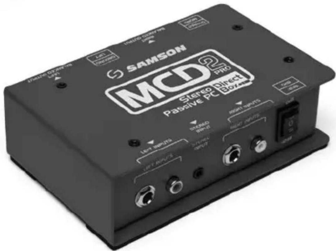
Samson's S-Max Direct Boxes combines premium sound circuitry with durable, roadworthy construction to provide high-quality signal connection solutions for live and studio applications. The Samson MCD2 Pro Professional Stereo Passive Direct Box offers a variety of DI solutions for live sound and recording applications. You can connect all kinds of audio signals like those from computers, CD/MP3 players, keyboards, and DJ equipment.
Featuring two of Samson's STLX Faraday shielded transformer, which deliver an extended, flat frequency response, ultra-low distortion, and eliminates hum and RF interference. The MCD2 Pro balanced output provide a clean signal, that is less susceptible to noise when compared to an unbalanced cable, which allows for running longer lengths of cables. Another benefit from a balanced connection is CMR (Common Mode Rejection), which provides cancellation of interference (hums and buzzes), while leaving the original signal pure.
The input jacks are wired in parallel which enables you to tap off the signal from the input and pass the signal to an amplifier or monitor without affecting the original sound. The Stereo/Mono switch mixes the two input channels together for situations where the number of audio channels is at a premium.
With proper care and maintenance, your MCD2 Pro will operate trouble-free for many years. Should your direct box ever require servicing, a Return Authorization (RA) number must be obtained before shipping your unit to Samson. Without this number, the unit will not be accepted. Please call Samson at 1-800-3SAMSON (1-800-372-6766) for an RA number prior to shipping your unit. If your direct box was purchased outside of the United States, contact your local distributor for warranty details and service information.
Callouts
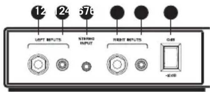
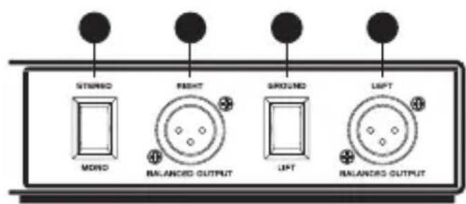
Front Rear
- 1/4" INPUT Jacks – 1/4" hi-Z input jacks for connecting for instruments or line level signals.
- RCA Input Jacks – Unbalanced RCA jacks for connecting line level signals. The RCA jacks are wired in parallel with the 1/4" and STEREO INPUT jacks.
- STEREO INPUT Jack – 1/8" stereo input jack for connecting line level signals. The STEREO INPUT jack is wired in parallel with the 1/4" and RCA jacks.
- -12dB Pad switch – When engaged, the input level is attenuated by -12dB to prevent distortion when connecting high level signals.
- STEREO/MONO Switch – When the switch is in the STEREO position, each input is routed to its corresponding output. In the MONO position, the Left and Right input signals are summed together and fed to both Left and Right Output jacks.
- BALANCED OUTPUT Jacks – Male XLR low-Z connectors.
- GROUND LIFT Switch – When the switch is engaged, the input ground (shield) is disconnected.
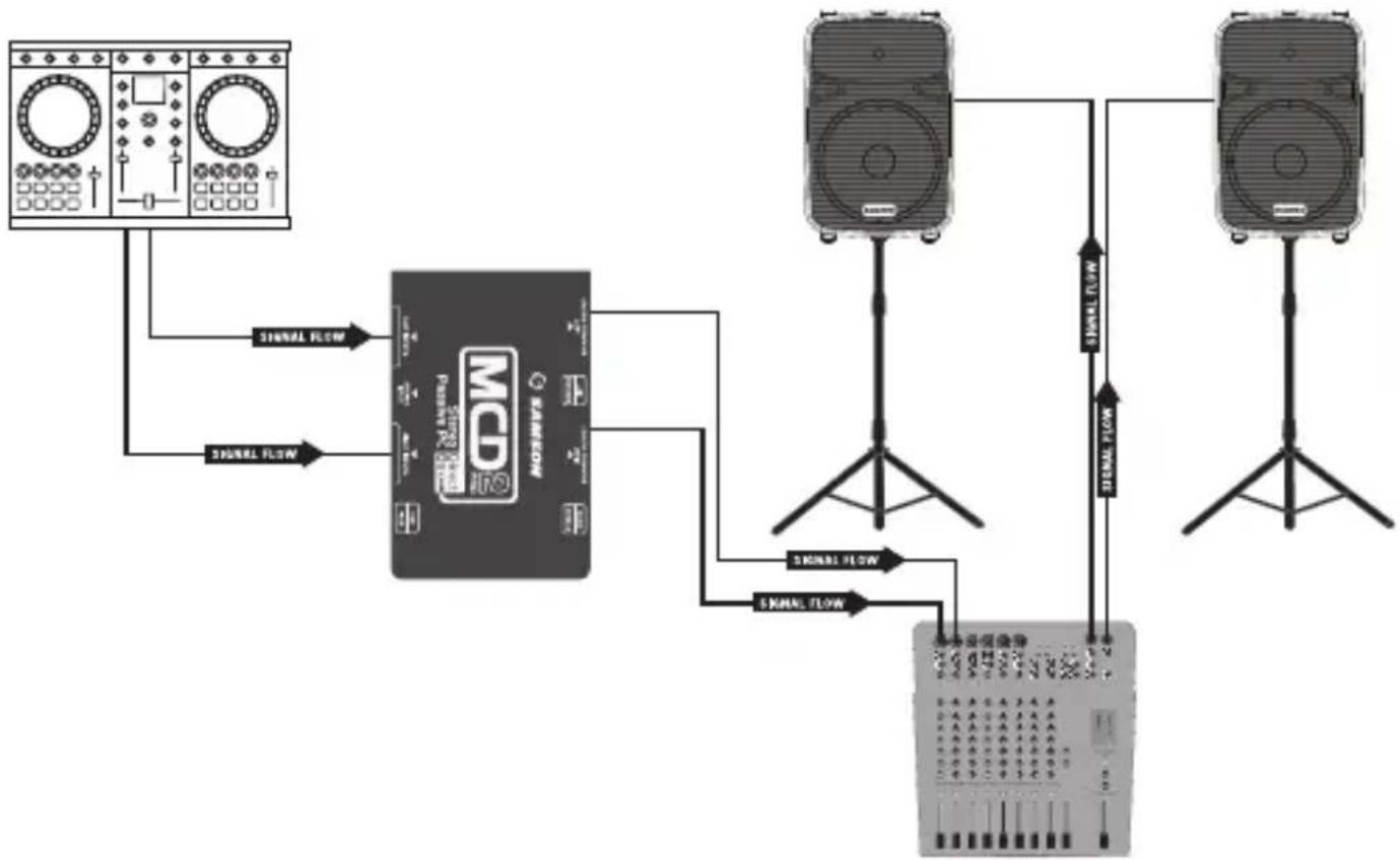
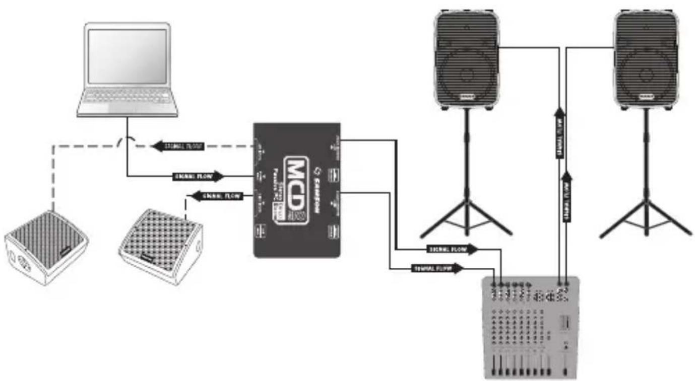
Setup
The MCD2 Pro can be quite useful on stage or in the studio for connecting unbalanced audio sources or instruments with pickups. By utilizing the MCD2 Pro, the signal can be sent cleanly for long distances while benefiting from the low noise and common mode rejection provided by the balanced low-level output. The diagram following shows a typical hook-up for a DJ Controller/Interface connected to a PA system.
flowchart
graph TD
    A["Input: Radioform"] --> B["RAMRON"]
    C["Input: Radioform"] --> B
    B --> D["Output: Speaker"]
    D --> E["Output: Speaker"]
    B --> F["Signal Flow"]
    B --> G["Signal Flow"]
    B --> H["Signal Flow"]
    B --> I["Signal Flow"]
    style B fill:#f9f,stroke:#333
    style D fill:#ccf,stroke:#333
    style E fill:#cfc,stroke:#333
    style F fill:#fcc,stroke:#333
    style G fill:#cff,stroke:#333
    style H fill:#ffc,stroke:#333
    style I fill:#fcc,stroke:#333
- Set the volume controls of your audio system to the off position.
- Connect the stereo outputs of your DJ Controller/Interface or other audio source to the Left and Right Input jacks of the MCD2 Pro.
- Connect the Left and Right BALANCED OUTPUT jacks to a pair of microphone inputs of a mixer or other audio device.
- Pan the input channels of the mixer left and right.
- Raise the level of the audio system to the appropriate level.
- If you hear a hum or buzz set the GROUND LIFT switch to the LIFT position.
- If you hear distortion, set the pad switch to the -12dB position. You may need to adjust the input level of the mixer to make up for the attenuated signal.
Connecting a Laptop
flowchart
graph TD
    A["Laptop"] -->|12.5mm/70Hz| B["MCD Chip"]
    C["Speaker"] -->|3.5mm/60Hz| B
    D["Audio System"] -->|3.5mm/60Hz| B
    B -->|Signal Flow| E["Speaker"]
    E -->|Signal Flow| F["Audio System"]
    B -->|Signal Flow| G["Speaker"]
    G -->|Signal Flow| H["Speaker"]
- Set the volume controls of your audio system to the off position.
- Connect the 1/8" stereo output of your laptop or other audio source to the STEREO Input jack of the MCD2 Pro.
- Connect the 1/4" parallel jacks to active monitor speakers.
- Connect the Left and Right BALANCED OUTPUT jacks to a pair of microphone inputs of a mixer or other audio device.
- Pan the input channels of the mixer left and right.
- Raise the level of the audio system to the appropriate level.
- If you hear a hum or buzz set the GROUND LIFT switch to the LIFT position.
- If you hear distortion, set the pad switch to the -12dB position. You may need to adjust the input level of the mixer to make up for the attenuated signal.
Specifications
Type Stereo Passive Direct Box
Frequency Response 18Hz to 40kHz ±0.1dB
Maximum Input +20dBu 0.35% THD
Dynamic Range >100dB @ Balanced Output
Noise Floor -117dB
Total harmonic distortion <0.03% from 20Hz to 40kHz
Input impedance 400kΩ (Stereo Switch Position)
10k (Mono Switch Position)
Output Impedance 250Ω ±20%
Transformers Two STLX Faraday Shielded Transformers
Transformer Ratio 15:1
Input PAD Switch 0dB, -12dB
Ground Lift Switch Disconnects XLR pin-1 (Output)
Stereo/Mono Switch Sums stereo inputs to both outputs
Connectors 1/4" Phone Jack, RCA, Stereo 1/8"
unbalanced
XLR balanced (Output)
Construction 14 gauge steel chassis
Dimensions 6.1" x 3.93" x 1.77"
155mm x 100mm x 45mm
Weight 2.11lb
957g
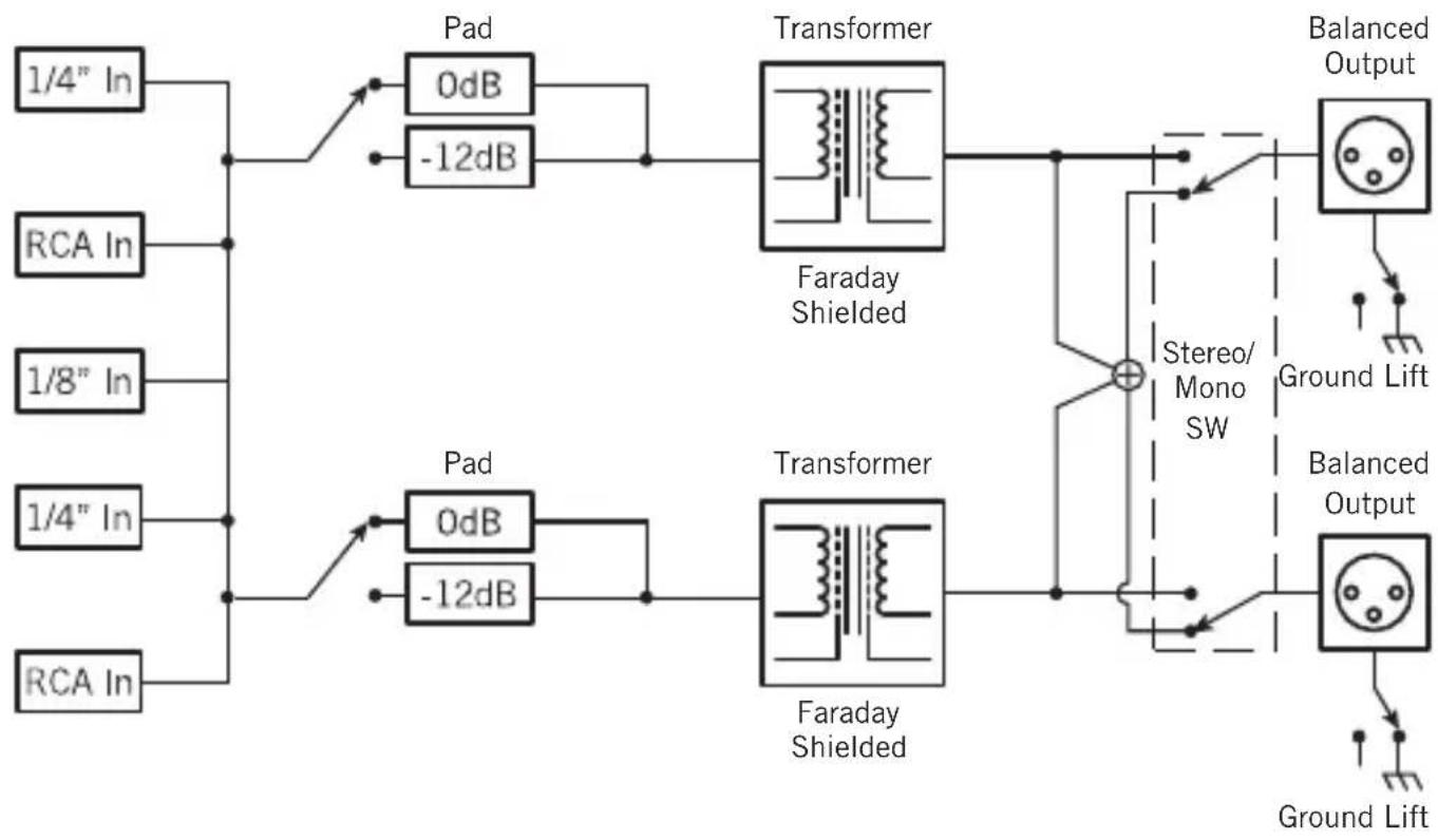
Block Diagram

flowchart
graph LR
    A["1/4" In"] --> B["Pad"]
    C["RCA In"] --> D["Pad"]
    E["1/8" In"] --> F["Pad"]
    G["1/4" In"] --> H["Pad"]
    I["RCA In"] --> J["Pad"]
    B --> K["0dB"]
    D --> L["-12dB"]
    F --> M["0dB"]
    H --> N["-12dB"]
    K --> O["Transformer"]
    L --> O
    M --> O
    N --> O
    O --> P["Faraday Shielded"]
    P --> Q["Stereo/Mono SW"]
    Q --> R["Balanced Output"]
    R --> S["Ground Lift"]
    S --> T["Balanced Output"]
    T --> U["Ground Lift"]
    U --> V["Ground Lift"]
    V --> W["Ground Lift"]
    W --> X["Balanced Output"]
    X --> Y["Balanced Output"]

Dimensions 6.1" x 3.93" x 1.77"
155 mm × 100 mm × 45 mm
Poids 2.11lb
957 g
Schéma fonctionnel

flowchart
graph LR
    A["1/4" In"] --> B["Pad 0dB"]
    C["RCA In"] --> D["Pad 0dB"]
    E["1/8" In"] --> F["Pad 0dB"]
    G["1/4" In"] --> H["Pad 0dB"]
    I["RCA In"] --> J["Pad 0dB"]
    B --> K["-12dB"]
    D --> L["-12dB"]
    F --> M["-12dB"]
    H --> N["-12dB"]
    K --> O["Transformer Faraday Shielded"]
    L --> P["Transformer Faraday Shielded"]
    O --> Q["Stereo/Mono SW"]
    P --> Q
    Q --> R["Balanced Output"]
    R --> S["Ground Lift"]
    S --> T["Balanced Output"]
    T --> U["Ground Lift"]
    U --> V["Ground Lift"]
    style A fill:#f9f,stroke:#333
    style C fill:#f9f,stroke:#333
    style E fill:#f9f,stroke:#333
    style G fill:#f9f,stroke:#333
    style I fill:#f9f,stroke:#333
    style Q fill:#ccf,stroke:#333
    style R fill:#ccf,stroke:#333
    style S fill:#ccf,stroke:#333
    style T fill:#ccf,stroke:#333

flowchart
graph LR
    A["1/4" In"] --> B["Pad"]
    C["RCA In"] --> D["Pad"]
    E["1/8" In"] --> F["Pad"]
    G["1/4" In"] --> H["Pad"]
    I["RCA In"] --> J["Pad"]
    B --> K["0dB"]
    D --> L["-12dB"]
    J --> M["0dB"]
    J --> N["-12dB"]
    K --> O["Transformer"]
    L --> O
    M --> P["Faraday Shielded"]
    N --> P
    O --> Q["+"]
    P --> R["Stereo/Mono SW"]
    Q --> S["Balanced Output"]
    R --> T["Balanced Output"]
    U["Balanced Output"] --> V["Ground Lift"]
    W["Balanced Output"] --> X["Ground Lift"]
    Y["Balanced Output"] --> Z["Ground Lift"]

155mm x 100mm x 45mm
Peso 2,11lb
957g
Diagrama de bloques
flowchart
graph LR
    A["1/4" In"] --> B["Pad"]
    C["RCA In"] --> D["Pad"]
    E["1/8" In"] --> F["Pad"]
    G["1/4" In"] --> H["Pad"]
    I["RCA In"] --> J["Pad"]
    B --> K["0dB"]
    D --> L["-12dB"]
    J --> M["0dB"]
    J --> N["-12dB"]
    K --> O["Transformer"]
    L --> O
    M --> P["Faraday Shielded"]
    N --> P
    O --> Q["+"]
    P --> R["Stereo/Mono SW"]
    Q --> S["Balanced Output"]
    R --> T["Balanced Output"]
    U["Balanced Output"] --> V["Ground Lift"]
    W["Balanced Output"] --> X["Ground Lift"]
    Y["Balanced Output"] --> Z["Ground Lift"]

Brand : SAMSON
Model : MCD 2 Pro
Category : Hi-fi system