
DSPA1 - Home cinema amp YAMAHA - Free user manual and instructions
Find the device manual for free DSPA1 YAMAHA in PDF.
User questions about DSPA1 YAMAHA
0 question about this device. Answer the ones you know or ask your own.
Ask a new question about this device
Download the instructions for your Home cinema amp in PDF format for free! Find your manual DSPA1 - YAMAHA and take your electronic device back in hand. On this page are published all the documents necessary for the use of your device. DSPA1 by YAMAHA.
USER MANUAL DSPA1 YAMAHA
natural_image
Technical line drawing of a door panel with control buttons and a rotary knob (no text or symbols)• Batteries (size AA, R6, UM-3)
• Piles (taille AA, R6, UM-3)
• Batterien (Größe AA, R6, UM-3)
• Batterier (storlek AA, R6, UM-3)
• Batterie (dimensioni AA, R6, UM-3)
• Pilas (tamaño AA, R6, UM-3)
• Batterijen (maat AA, R6, UM-3)
• User function stickers
• Etiquettes de fonctions d'utilisateur
• Etiketten für Anwenderfunktionen
• Etiketter för din egen användning
• Etichette ad uso dell'utente
- Etiqueta de funciones del usuario
- Gebruikersfunctie-stickers
natural_image
Grid of empty rectangular boxes with no text or symbolsCONTENTS
SUPPLIED ACCESSORIES
Inside of the Front Cover
FEATURES 2
CAUTION 3
NOTES ABOUT THE REMOTE CONTROL
TRANSMITTER 4
PROFILE OF THIS UNIT 5
SPEAKER SETUP 8
CONNECTIONS 10
CONNECTING AUDIO/VIDEO SOURCE EQUIPMENT
TO THIS UNIT 10
CONNECTING SPEAKERS.... 18
PLUGGING IN THIS UNIT 22
CONTROLS AND THEIR FUNCTIONS .... 23
FRONT PANEL 23
DISPLAY PANEL 25
ADJUSTMENTS BEFORE USING THIS UNIT ...... 26
SELECTING THE OUTPUT MODES SUITABLE FOR
YOUR SPEAKER SYSTEM (IN THE "SET MENU" MODE) 26
SPEAKER BALANCE ADJUSTMENT 29
ADJUSTMENTS IN THE "SET MENU" MODE ...... 32
BASIC OPERATIONS 39
TO PLAY A SOURCE.... 39
TO RECORD A SOURCE TO TAPE (OR MD)
(OR DUBBING FROM A TAPE TO ANOTHER)...... 42
FOR SOUND CONTROL ON THIS UNIT.... 44
USING DIGITAL SOUND FIELD PROCESSOR (DSP)
45
PLAYING A SOURCE WITH AN EFFECT OF THE
DIGITAL SOUND FIELD PROCESSOR (DSP) 45
ADJUSTING OUTPUT LEVEL OF THE CENTER, RIGHT
REAR, LEFT REAR, FRONT EFFECT SPEAKERS AND
SUBWOOFER 48
BRIEF OVERVIEW OF DIGITAL SOUND FIELD
PROGRAMS 50
ON SCREEN DISPLAY 55
CREATING YOUR OWN SOUND FIELDS .... 56
SELECTING AND EDITING PROGRAM PARAMETERS
57
DESCRIPTIONS OF THE DIGITAL SOUND FIELD
PARAMETERS 58
SETTING THE SLEEP TIMER 61
REMOTE CONTROL TRANSMITTER 62
BASIC OPERATIONS (When the lid is open) 62
LEARNING NEW CONTROL FUNCTIONS
(When the lid is open).... 64
(When the lid is closed) 66
MACRO OPERATIONS (When the lid is closed) ...... 68
LEARNING A NEW FUNCTION 70
MAKING A NEW MACRO 71
CLEARING LEARNED FUNCTIONS 72
TROUBLESHOOTING 73
SPECIFICATIONS 76
FEATURES
• 7 Speaker Configuration
Main: 110W + 110W (8Ω) RMS Output
Power, 0.015% THD, 20–20,000 Hz
Center: 110W (8Ω) RMS Output Power, 0.015% THD, 20–20,000 Hz
Rear: 110W + 110W (8Ω) RMS Output Power, 0.015% THD, 20–20,000 Hz
Front: 35W + 35W (8Ω) RMS Output
Power, 0.05% THD, 1 kHz
• Digital Sound Field Processor
• Dolby Digital (AC-3) Decoder
• Dolby Pro Logic Surround Decoder
- DTS Decoder
- CINEMA DSP: Theater-like Sound Experience by the Combination of YAMAHA DSP Technology and Dolby Surround or DTS
• Automatic Input Balance Control for Dolby Pro Logic Surround
- Test Tone Generator for Easier Speaker Balance Adjustment
- Speaker Output Mode Changing Capability
- “SET MENU” Mode which Provides You with 12 Titles of Setting Changes and Adjustments for Using This Unit in the Best Condition in Your Audio/Video System
- BASS EXTENSION Switch for Reinforcing Bass Response
- On Screen Display Function Helpful in Controlling This Unit
- REC OUT Selector which is Independent of Input Source Selection
- SLEEP Timer
- Digital Audio Signal Terminals: 5 OPTICAL Inputs, 3 COAXIAL Inputs, 1 DOLBY DIGITAL (AC-3) RF Input, 1 OPTICAL Output
- 6 Channel Audio Signal Input Terminals for Connecting with an External Audio Signal Decoder etc. (e.g. MPEG 2 for areas which employs the PAL video signal format only)
• Video Signal Input/Output Capability (Including S Video Connections) - “Learning” Remote Control Transmitter
CAUTION : READ THIS BEFORE OPERATING YOUR UNIT.
- To assure the finest performance, please read this manual carefully. Keep it in a safe place for future reference.
- Install this unit in a cool, dry, clean place – away from windows, heat sources, sources of excessive vibration, dust, moisture and cold. Avoid sources of humming (transformers, motors). To prevent fire or electrical shock, do not expose the unit to rain or water.
- Never open the cabinet. If something drops into the set, contact your dealer.
- Do not use force on switches, controls or connection wires. When moving the unit, first disconnect the power plug and the wires connected to other equipment. Never pull the wires themselves.
- The openings on the cabinet assure proper ventilation of the unit. If these openings are obstructed, the temperature inside the cabinet will rise rapidly. Therefore, avoid placing objects against these openings, and install the unit in well-ventilated condition. Make sure to allow a space of at least 10 cm behind, 10 cm on the both sides and 30 cm above the top panel of the unit. Otherwise it may not only damage the unit, but also cause fire.
- The voltage to be used must be the same as that specified on this unit. Using this unit with a higher voltage than that which is specified is dangerous and may result in a fire or other type of accident causing damage. YAMAHA will not be held responsible for any damage resulting from use of this unit with a voltage other than that which is specified.
- Digital signals generated by this unit may interfere with other equipment such as tuners, receivers or TVs. Move this unit farther away from such equipment if interference is observed.
- Always set the VOLUME control to “-∞” before starting the audio source play. Increase the volume gradually to an appropriate level after playback has been started.
- Do not attempt to clean the unit with chemical solvents; this might damage the finish. Use a clean, dry cloth.
- Be sure to read the "TROUBLESHOOTING" section regarding common operating errors before concluding that the unit is faulty.
- When not planning to use this unit for long periods of time (ie., vacation, etc.), disconnect the AC power plug from the wall outlet.
- To prevent lightning damage, disconnect the AC power plug and antenna cable when there is an electrical storm.
- Grounding or polarization – Precautions should be taken so that the grounding or polarization of an appliance is not defeated.
- Do not connect an audio equipment to the AC outlet on the rear panel if the equipment requires more power than the outlet is rated to provide.
- Voltage Selector (China and General Models only) The voltage selector on the rear panel of this unit must be set for your local main voltage BEFORE plugging into the AC main supply. Voltages are 110/120/220/240 V AC, 50/60 Hz.
This unit is not disconnected from the AC power source as long as it is connected to the wall outlet, even if this unit itself is turned off. This state is called the standby mode. In this state, this unit is designed to consume a very small quantity of power.
IMPORTANT
Please record the serial number of this unit in the space below.
Model:
Serial No.:
The serial number is located on the rear of the unit. Retain this Owner's Manual in a safe place for future reference.
WARNING
TO REDUCE THE RISK OF FIRE OR ELECTRIC SHOCK, DO NOT EXPOSE THIS UNIT TO RAIN OR MOISTURE.
FREQUENCY STEP switch (China and General Models only)
Because the interstation frequency spacing differs in different areas, set the FREQUENCY STEP switch (located at the rear) according to the frequency spacing in your area. Before setting this switch, disconnect the AC power plug of this unit from the AC outlet.
FOR CANADIAN CUSTOMERS
TO PREVENT ELECTRIC SHOCK, MATCH WIDE BLADE OF PLUG TO WIDE SLOT AND FULLY INSERT.
THIS CLASS B DIGITAL APPARATUS MEETS ALL REQUIREMENTS OF THE CANADIAN INTERFERENCE-CAUSING EQUIPMENT REGULATIONS.
WARNING
Do not change the IMPEDANCE SELECTOR switch setting while the power to this unit is on, otherwise this unit may be damaged.
IF THIS UNIT FAILS TO TURN ON WHEN THE STANDBY/ON SWITCH IS PRESSED;
The IMPEDANCE SELECTOR switch may not be set to either end closely. If so, set the switch to either end closely.
For U.K. customers
If the socket outlets in the home are not suitable for the plug supplied with this appliance, it should be cut off and an appropriate 3 pin plug fitted. For details, refer to the instructions described below.
Note: The plug severed from the mains lead must be destroyed, as a plug with bared flexible cord is hazardous if engaged in a live socket outlet.
Special Instructions for U.K. Model
IMPORTANT
THE WIRES IN MAINS LEAD ARE COLOURED IN ACCORDANCE WITH THE FOLLOWING CODE:
Blue: NEUTRAL
Brown: LIVE
As the colours of the wires in the mains lead of this apparatus may not correspond with the coloured markings identifying the terminals in your plug, proceed as follows: The wire which is coloured BLUE must be connected to the terminal which is marked with the letter N or coloured BLACK. The wire which is coloured BROWN must be connected to the terminal which is marked with the letter L or coloured RED. Making sure that neither core is connected to the earth terminal of the three pin plug.
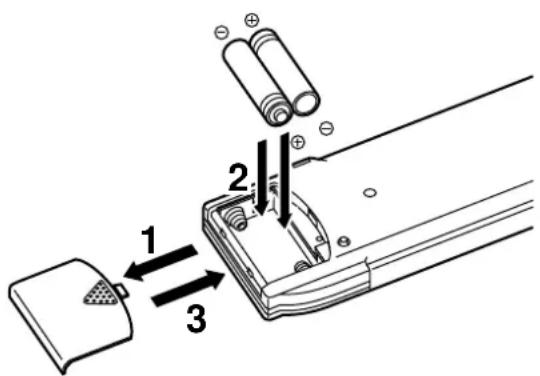
NOTES ABOUT THE REMOTE CONTROL TRANSMITTER
Battery installation
Battery replacement
If you find that the remote control transmitter must be used closer to the main unit, the batteries are weak. Replace both batteries with new ones.
Notes
• Use only AA, R6, UM-3 batteries for replacement.
- Be sure the polarities are correct. (See the illustration inside the battery compartment.)
- Remove the batteries if the remote control transmitter will not be used for an extended period of time.
- If batteries leak, dispose of them immediately. Avoid touching the leaked material or letting it come in contact with clothing, etc. Clean the battery compartment thoroughly before installing new batteries.
- After you change batteries, make sure to press the RESET button inside the battery compartment.
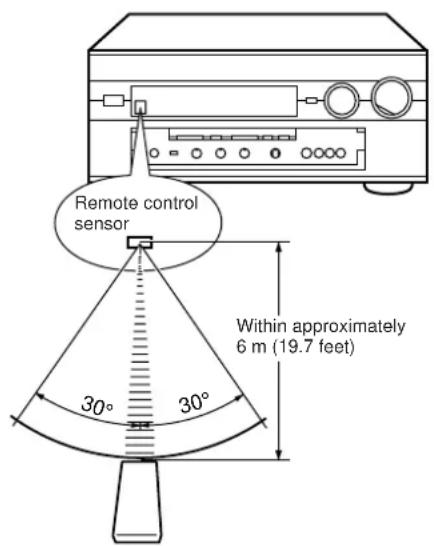
Remote control transmitter operation range
Notes
- There should be no large obstacles between the remote control transmitter and the main unit.
- If the remote control sensor is directly illuminated by strong lighting (especially an inverter type of fluorescent lamp etc.), it might cause the remote control transmitter not to work correctly. In this case, reposition the main unit to avoid direct lighting.
PROFILE OF THIS UNIT
This unit incorporates a sophisticated, multi-program digital sound field processor. The processor allows you to electronically expand and change the shape of the audio sound field from both audio and video sources, creating a theater-like experience in your listening room. This unit has a total of 12 digital sound field processor (DSP) modes. You can create an excellent audio sound field by selecting a suitable sound field (this will, of course, depend on what you will be listening to), and adding desired adjustments.
In addition, this unit incorporates a Dolby Pro Logic Surround decoder and Dolby Digital (AC-3) decoder for multi-channel sound reproduction of Dolby Surround encoded video sources, and a DTS decoder for multi-channel sound reproduction of DTS-encoded audio and video sources. The operation of the Dolby Pro Logic Surround, Dolby Digital (AC-3) or DTS decoder can be controlled by selecting a corresponding DSP program including combined operations of DSP and Dolby Pro Logic Surround, DSP and Dolby Digital (AC-3), or DSP and DTS.
This unit also features a built-in automatic input balance control. This always assures you the best performance without manual adjustment.
Digital Sound Field Processing
What is it that makes live music so good? Today's advanced sound reproduction technology lets you get extremely close to the sound of a live performance, but chances are you'll still notice something missing, the acoustic environment of the live concert hall. Extensive research into the exact nature of the sonic reflections that create the ambience of a large hall has made it possible for Yamaha engineers to bring you this same sound in your own listening room, so you'll feel all the sound of a live concert.
Furthermore, our technicians, armed with sophisticated measuring equipment, have even made it possible to capture the acoustics of a variety of actual concert halls, jazz clubs, theaters, etc. from around the world, to allow you to accurately recreate any one of these live performance environments, all in your own home.
Dolby Pro Logic Surround
This unit employs a Dolby Pro Logic Surround decoder similar to professional Dolby Stereo decoders used in many movie theaters. By using the Dolby Pro Logic Surround decoder, you can experience the dramatic realism and impact of Dolby Stereo theater sound in your own home.
Dolby Pro Logic employs a four-channel-five-speaker system. The Pro Logic Surround system divides the input signal into four levels: the left and right main channels, the center channel (used for dialog), and the rear surround sound channel (used for sound effects, background noise, and other ambient noises). The center channel allows listeners seated in even less-than-ideal positions to hear the dialog originating from the action on the screen while experiencing good stereo imaging.
Dolby Surround is encoded on a lot of sound tracks of pre-recorded video tapes, laserdiscs, and some TV/cable broadcasts. When you play a source encoded with Dolby Surround on this unit, the Dolby Pro Logic Surround decoder decodes the signal and distributes the surround-sound effects.
Dolby Digital (AC-3)
Dolby Digital (AC-3) is a new generation of Dolby Surround sound system which is a spatial sound processing format developed for 35 mm film-movies by employing low bit-rate audio coding.
Dolby Digital (AC-3) is a digital surround sound system that provides completely independent multi-channel audio to consumers. In multi-channel form, Dolby Digital (AC-3) provides five full range channels in what is sometimes referred to as a "3/2" configuration: three front channels (left, center and right), plus two surround channels. A sixth bass-only effect channel is also provided for output of LFE (low frequency effect), or low bass effects that are independent of other channels. (This is called the "subwoofer channel" or "LFE channel".) This channel is counted as 0.1, thus giving rise to the term 5.1 channels in total.
Compared to Dolby Pro Logic that is referred to a "3/1" system (left front, center, right front and just one surround channel), Dolby Digital (AC-3) features two surround channels, called stereo or split surrounds, each offering the same full range fidelity as the three front channels.
By using the built-in Dolby Digital (AC-3) decoder, you can experience the dramatic realism and impact of Dolby Stereo Digital theater sound in your own home.
Sound of wide dynamic range reproduced by the five full range channels presents listeners much excitement that has never been experienced before. Precise sound orientation by the discrete digital sound processing expands realism that the original movie possesses.
Dolby Digital (AC-3) forms 5.1 channels as mentioned on the previous page, and moreover, it can also form fewer channels, for example 2 channel stereo and monaural. You may be able to find some 2 channel stereo and/or monaural sources encoded with the Dolby Digital (AC-3) in a market.
If a 2 channel stereo source encoded with the Dolby Digital (AC-3) is played back as the input source and the DSP program No. 10, 11 or 12 is used at the same time, the source is first decoded with the Dolby Digital (AC-3) decoder into 2 channels, and then decoded with the Dolby Pro Logic decoder. In such a case, only the decoding of Dolby Pro Logic is shown on the display panel of this unit.
Laserdisc and DVD are home audio formats that could benefit from Dolby Digital (AC-3). In the near future, Dolby Digital (AC-3) will also be applied to DBS, CATV and HDTV. The ongoing release of Dolby Stereo Digital theatrical films now underway will provide an immediate source of Dolby Digital (AC-3) encoded video software.
DOLBY DIGITAL
Manufactured under license from Dolby Laboratories Licensing Corporation. "Dolby", "AC-3", "Pro Logic", and the double-D symbol are trademarks of Dolby Laboratories Licensing Corporation.
Copyright 1992 Dolby Laboratories, Inc. All rights reserved.
DTS Digital Surround
The DTS (Digital Theater Systems) system was developed to replace analog soundtracks of movies with six discrete channels of digital soundtracks, and now, it is installed in many theaters around the world. The DTS digital playback system changed the way we experienced movies in theaters with six discrete channels of superb digital audio.
The DTS technology, through intense research and development, made it possible to deliver a similar encode/decode discrete technology to home audio surround-sound entertainment.
The DTS Digital Surround is an encode/decode system which delivers six channels of master-quality, 20-bit audio; technically 5.1 channels, which means 5 full-range (left, center, right and two surround) channels, plus a subwoofer (LFE) channel (as "0.1"). It is compatible with the 5.1 speaker configurations that are currently available for home theater systems
The DTS Digital Surround algorithm is designed to encode the six channels of 20-bit audio onto any laserdisc or compact disc (or DVD in the near future) with considerably less data-compression.
By using the DTS decoder built into this unit, you can experience the dramatic realism and impact of the DTS installed theater's high quality sound in your own home.
Laserdisc and compact disc (and DVD in the near future) are home audio format within which DTS can represent its high quality multi-channel audio. (In addition to movies on laserdiscs, many exciting new multi-channel music recordings will also become available in the form of DTS-encoded compact discs.)
dts
Manufactured under license from DTS Technology LLC. Additionally licensed under the following US Patent 5,451,942 & National Patent applications derived from PCT/US95/00959. Additional U.S. and Foreign Patents pending. "DTS", "digital surround", and "coherent acoustics" logos are trademarks of DTS Technology LLC. All rights reserved.
Dolby Surround sound system and DTS system show their full ability in a large movie theater, because movie sounds are originally designed to be reproduced in a large movie theater using many speakers. It is difficult to create a sound environment similar to that of a movie theater in your listening room, because the room size, materials of inside walls, the number of speakers, etc. of your listening room are much different from those of a movie theater.
Yamaha DSP technology made it possible to present you with nearly the same sound experience as that of a large movie theater in your listening room by compensating for lack of presence and dynamics in your listening room with its original digital sound fields combined with Dolby Surround sound or DTS Digital Surround sound.
CINEMA DSP
The YAMAHA "CINEMA DSP" logo indicates those programs are created by the combination of YAMAHA DSP technology and Dolby Surround or DTS.
Dolby Pro Logic + 2 Digital Sound Fields
Digital sound fields are created on the presence side and the rear surround side of the Dolby Pro Logic Surround-decoded sound field respectively. They create a wide acoustic environment and emphasize surround-effect in the room, letting you feel much presence as if you were watching a movie in a popular Dolby Stereo theater.
This combination is available when the digital sound field program No. 7, 8, 9, 10, 11 or "PRO LOGIC/Enhanced" of No. 12 is selected, and the input signal of source is analog, PCM audio or encoded with the Dolby Digital (AC-3) in 2-channels.

natural_image
Simple line drawing of a device with three dots above and a small flame icon inside, enclosed in a gray rounded rectangle (no text or symbols)Dolby Digital (AC-3) or DTS + 3 Digital Sound Fields
Digital sound fields are created on the presence side and the independent left and right surround sides of the Dolby Digital (AC-3)- decoded or the DTS-decoded sound field respectively. They create a wide acoustic environment and much surround effect in the room without losing high channel separation. With wide dynamic range of Dolby Digital (AC-3) or DTS sound, this sound field combination lets you feel as if you were watching a movie in the newest Dolby Stereo Digital theater or DTS installed theater. This will be the most ideal home theater sound at the present time.
This combination is available when the digital sound field program No. 7, 8, 9, 10, 11 or "DOLBY DIGITAL (or DTS DIGITAL SUR.)/Enhanced" of No. 12 is selected, and the input signal of source is encoded with the Dolby Digital (AC-3) (except in 2-channels) or encoded with the DTS.

natural_image
Abstract diagram with three overlapping circles and a central rectangular block containing a fruit icon (no text or symbols)SPEAKER SETUP
Setting Up Your Speaker System
This unit has been designed to provide the best sound field quality with a full seven-speaker system setup, using a pair of main speakers to output main source sounds, two extra pairs of effect speakers to generate the sound field plus one center speaker for dialog. We therefore recommend that you use a seven-speaker setup. A four-speaker system using only one pair of effect speakers for the sound field will still provide impressive ambience and effects, however, and may be a good way to begin with this unit. You can always upgrade to the full seven-speaker system later. In the 4 or 5 speaker system, the Digital Sound Field Processing is still performed, but the main speakers are used for both the main channels and the front effect channels.
Use of the Center Dialog Speaker Is Recommended
When playing back a source with the Dolby Pro Logic decoded, or playing back a source which contains center-channel signals with the Dolby Digital (AC-3) or the DTS decoded, dialog, vocals etc. are output from the center channel. Therefore, if you want to maximize the performance of your Audio/Video home theater system, it is recommended that you use a center channel speaker.
If for some reason it is not practical to use a center speaker, it is possible to enjoy movie viewing without it. Best results, however, are obtained with the full system.
Use of a Subwoofer Expands Your Sound Field
It is also possible to further expand your system with the addition of a subwoofer and amplifier. The use of a subwoofer is effective not only for reinforcing bass frequencies from any or all channels, but also for reproducing signals at the subwoofer channel with high fidelity during playing back a source with the Dolby Digital (AC-3) or the DTS decoded. You may wish to choose the convenience of a Yamaha Active Servo Processing Subwoofer System, which has its own built-in power amplifier.
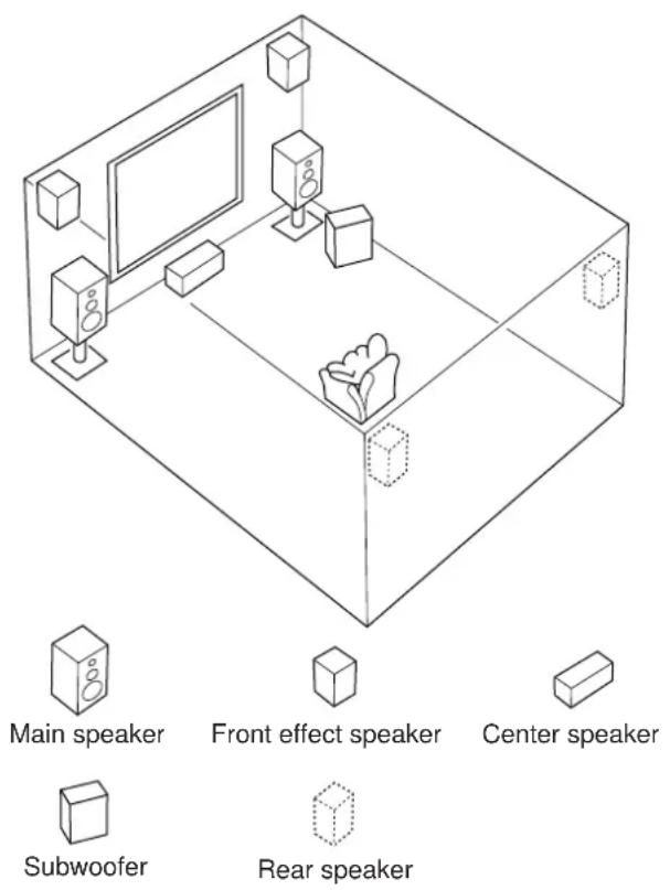
Speakers and Speaker Placement
Your full seven-speaker system will require three speaker pairs: the MAIN SPEAKERS (your normal stereo speakers), the FRONT EFFECT SPEAKERS and the REAR SPEAKERS, plus the CENTER SPEAKER. You may also be using a SUBWOOFER.
The MAIN SPEAKERS should be high performance models and have enough power handling capacity to accept the maximum output of your audio system.
Other speakers do not have to be equal to the MAIN SPEAKERS. For precise sound localization, however, it is ideal to use high performance models that can reproduce sounds in full range for the CENTER SPEAKER, the FRONT EFFECT and REAR SPEAKERS.
Place the MAIN SPEAKERS in the normal position.
Place the FRONT EFFECT SPEAKERS further apart than the MAIN SPEAKERS, on either side of and 0.5–1m behind and above the MAIN SPEAKER pair.
Place the REAR SPEAKERS behind your listening position. They should be nearly 1.8m up from the floor.
Place the CENTER SPEAKER precisely between the two MAIN SPEAKERS. (To avoid interference, keep the speaker above or below the television monitor, or use a magnetically shielded speaker.)
If using a SUBWOOFER, such as a Yamaha Active Servo Subwoofer System, the position of the speaker is not so critical because low bass tones are not highly directional.
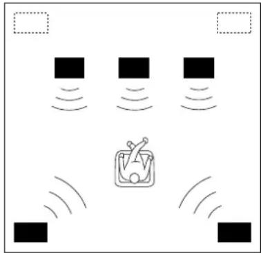
4 Speaker System
natural_image
Diagram showing a device emitting sound waves with no text or symbolsSimplest system.
You can enjoy widely diffused sound by only adding two additional speaker units at the rear.
1E. FRONT MIX—Set to ON-5ch. (See page 27.)
1A. CENTER SP—Set to NONE. (See page 26.)
5 Speaker System
natural_image
Diagram showing four black squares with sound waves and a central icon resembling a TV or radio (no text or symbols)Good for Audio/Video sources.
By the use of center speaker, center sounds (dialog, vocals etc.) are precisely localized.
1E. FRONT MIX—Set to ON-5ch. (See page 27.)
1A. CENTER SP—Set to LRG or SML. (See page 26.)
6 Speaker System
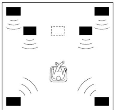
natural_image
Diagram showing wireless signal propagation around a central device (no text or symbols)Good for sound fields from 2-channel stereo sources.
When a normal stereo source is played back with the sound field programs No. 1 through No. 6, a sound effect matching that of a 7-speaker system can be obtained. The addition of front left and right effect speakers produces a more effective sound field.
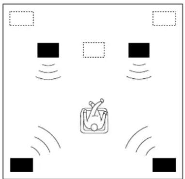
7 Speaker System
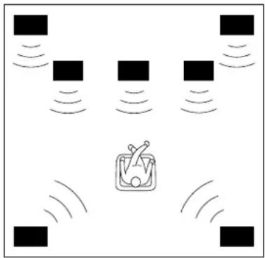
natural_image
Diagram showing multiple square blocks with wireless signals and a central icon depicting a person (no text or symbols)This is the recommended speaker system, providing the best sound effects.
The rear speakers and the front effect speakers produces a 360-degree sound field, and the center speaker provides precise center localization.
You can experience the amazing YAMAHA "CINEMA DSP" sound fields completely with the 7 speaker system.
1E. FRONT MIX—Set to OFF-7ch. (See page 27.)
1A. CENTER SP—Set to NONE. (See page 26.)
1E. FRONT MIX—Set to OFF-7ch. (See page 27.)
1A. CENTER SP—Set to LRG or SML. (See page 26.)
CONNECTIONS
Never plug in this unit and other components until all connections are completed.
When making connections between this unit and other components, be sure all connections are made correctly, that is to say L (left) to L, R (right) to R, “+” to “+” and “-” to “-”. Also, refer to the owner's manual for each component to be connected to this unit.
CONNECTING AUDIO/VIDEO SOURCE EQUIPMENT TO THIS UNIT
For connections with audio/video units, use RCA type pin plug cables with the exception described later.
* If you have YAMAHA audio/video units numbered as 1, 2, 3, etc. on the rear panel, connections can be made easily only by connecting the output (or input) terminals of each unit to the same-numbered terminals of this unit.
BASIC CONNECTIONS (for Audio Units)

flowchart
graph TD
    A["Tuner"] -->|OUTPUT| B["CD player"]
    C["MD recorder, Tape deck 1, etc."] -->|LINE OUT LINE IN| B
    D["Tape deck 2"] -->|LINE OUT LINE IN| B
    B --> E["Line OUT"]
    B --> F["Line OUT"]
    B --> G["Line OUT"]
    style A fill:#f9f,stroke:#333
    style C fill:#f9f,stroke:#333
    style D fill:#f9f,stroke:#333
    style E fill:#ccf,stroke:#333
    style F fill:#ccf,stroke:#333
    style G fill:#ccf,stroke:#333
    subgraph "General model"
        H["Turntable"] --> I["GND OUTPUT"]
        J["CD player"] --> K["OUTPUT"]
        L["Tuner"] --> M["OUTPUT"]
        N["MD recorder"] --> O["LINE OUT LINE IN"]
        P["Tape deck 2"] --> Q["LINE OUT LINE IN"]
        R["Line OUT"] --> S["Line OUT LINE IN"]
        T["Line OUT"] --> U["Line OUT LINE IN"]
        V["Line OUT"] --> W["Line OUT LINE IN"]
        X["Line OUT"] --> Y["Line OUT LINE IN"]
        Z["Line OUT"] --> AA["Line OUT LINE IN"]
        AB["Line OUT"] --> AC["Line OUT LINE IN"]
        AD["Line OUT"] --> AE["Line OUT LINE IN"]
        AF["Line OUT"] --> AG["Line OUT LINE IN"]
        AH["Line OUT"] --> AI["Line OUT LINE IN"]
        AJ["Line OUT"] --> AK["Line OUT LINE IN"]
        AL["Line OUT"] --> AM["Line OUT LINE IN"]
        AN["Line OUT"] --> AO["Line OUT LINE IN"]
        AP["Line OUT"] --> AQ["Line OUT LINE IN"]
        AR["Line OUT"] --> AS["Line OUT LINE IN"]
        AT["Line OUT"] --> AU["Line OUT LINE IN"]
        AV["Line OUT"] --> AW["Line OUT LINE IN"]
        AX["Line OUT"] --> AY["Line OUT LINE IN"]
        AZ["Line OUT"] --> BA["Line OUT LINE IN"]
        BB["Line OUT"] --> BC["Line OUT LINE IN"]
        BD["Line OUT"] --> BE["Line OUT LINE IN"]
        BF["Line OUT"] --> BG["Line OUT LINE IN"]
        BH["Line OUT"] --> BI["Line OUT LINE IN"]
        BJ["Line OUT"] --> BK["Line OUT LINE IN"]
        BL["Line OUT"] --> BM["Line OUT LINE IN"]
        BN["Line OUT"] --> BO["Line OUT LINE IN"]
        BP["Line OUT"] --> BQ["Line OUT LINE IN"]
        BR["Line OUT"] --> BS["Line OUT LINE IN"]
        BT["Line OUT"] --> BU["Line OUT LINE IN"]
        BV["Line OUT"] --> BW["Line OUT LINE IN"]
        BX["Line OUT"] --> BY["Line OUT LINE IN"]
        BZ["Line OUT"] --> BQ
        CC["Line OUT"] --> BB
        DD["Line OUT"] --> BC
        EY["Line OUT"] --> Z
    end
^* ^1 : GND terminal (For turntable use)
Connecting the ground wire of the turntable to the GND terminal will normally minimize hum, but in some cases better results may be obtained with the ground wire disconnected.
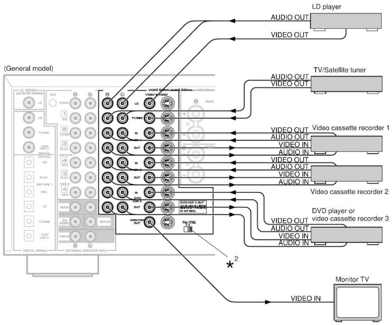
BASIC CONNECTIONS (for Video Units)
flowchart
graph TD
    A["General model"] --> B["LD player"]
    A --> C["TV/Satellite tuner"]
    A --> D["Monitor TV"]
    B --> E["VIDEO OUT"]
    B --> F["VIDEO OUT"]
    C --> G["VIDEO OUT"]
    C --> H["VIDEO OUT"]
    D --> I["VIDEO OUT"]
    D --> J["VIDEO OUT"]
    E --> K["Video cassette recorder 1"]
    E --> L["Video cassette recorder 2"]
    E --> M["Video cassette recorder 3"]
    F --> N["Video cassette recorder 1"]
    F --> O["Video cassette recorder 2"]
    F --> P["Video cassette recorder 3"]
    G --> Q["Video cassette recorder 1"]
    G --> R["Video cassette recorder 2"]
    G --> S["Video cassette recorder 3"]
    H --> T["Video cassette recorder 1"]
    H --> U["Video cassette recorder 2"]
    H --> V["Video cassette recorder 3"]
    I --> W["Video IN"]
    J --> X["Video IN"]
    K --> Y["Video OUT"]
    L --> Z["Video OUT"]
    M --> AA["Video OUT"]
    N --> AB["Video OUT"]
    O --> AC["Video OUT"]
    P --> AD["Video OUT"]
    Q --> AE["Main"]
    R --> AF["Main"]
    S --> AG["Main"]
    T --> AH["Main"]
    U --> AI["Main"]
    V --> AJ["Main"]
    W --> AK["Main"]
    X --> AL["Main"]
    Y --> AM["Main"]
    Z --> AN["Main"]
    AA --> AO["Main"]
    AB --> AP["Main"]
    AC --> AQ["Main"]
    AD --> AR["Main"]
    AE --> AS["Main"]
    AF --> AT["Main"]
    AG --> AU["Main"]
    AH --> AV["Main"]
    AI --> AW["Main"]
    AJ --> AX["Main"]
    AK --> AY["Main"]
    AL --> AZ["Main"]
    AM --> BA["Main"]
    AN --> BB["Main"]
    AO --> BC["Main"]
    AP --> BD["Main"]
    AQ --> BE["Main"]
    AR --> BF["Main"]
    AS --> BG["Main"]
    AT --> BH["Main"]
    AU --> BI["Main"]
    AV --> BJ["Main"]
    AW --> BK["Main"]
    AX --> BL["Main"]
    AY --> BM["Main"]
    AZ --> BN["Main"]

PAL/NTSC switch (China and General models only)
This unit is designed for use with the NTSC and PAL television formats. Set this switch to the position for the format your monitor TV employs.
PAL: Outputs signals in the PAL format no matter which format (PAL or NTSC) of video signal is sent from an external video unit to this unit. Set to this position if your monitor TV employs the PAL format.
NTSC: Outputs signals in the NTSC format no matter which format (PAL or NTSC) of video signal is sent from an external video unit to this unit. Set to this position if your monitor TV employs the NTSC format.
Note
Be sure to input a video signal which employs the same format that your monitor TV employs, otherwise a picture will not be played back normally.
Note
If you wish to connect a second monitor TV (or a projector) to this unit, you can switch the DVD/VCR 3 VIDEO OUT terminal (and S VIDEO terminal also) to a second monitor out terminal for the connection with another monitor TV. (Refer to page 38.)
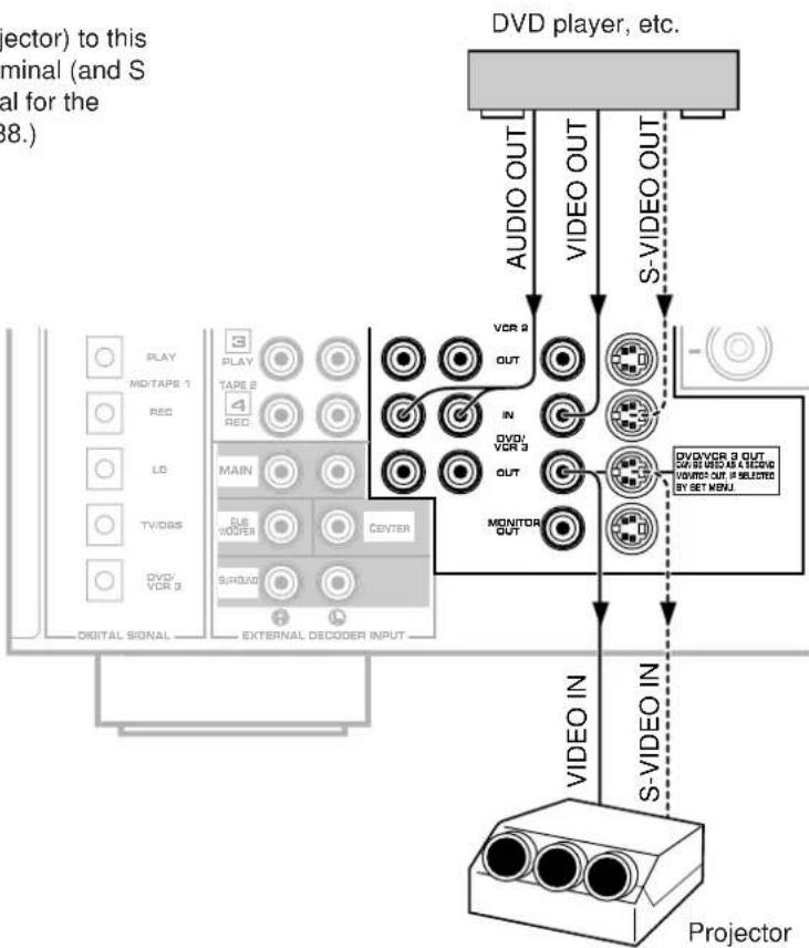
flowchart
graph TD
    A["VDV player, etc."] -->|AUDIO OUT| B["VIDEO OUT"]
    A -->|S-VIDEO OUT| C["VIDEO IN"]
    B --> D["VCR 2 OUT"]
    B --> E["IN"]
    B --> F["MONITOR OUT"]
    C --> G["S-VIDEO IN"]
    C --> H["VIDEO IN"]
    I["PROYCTOR"] --> J["VIDEO OUT"]
    I --> K["S-VIDEO IN"]
    L["PLAY MODE"] --> M["MO/TAPES 1"]
    L --> N["REC"]
    O["LD"] --> P["MAIN"]
    Q["TV/DBS"] --> R["USB WIDER CENTER"]
    S["DVD/VCR 3"] --> T["S/R/DVD"]
    U["DIGITAL SIGNAL"] --> V["EXTERNAL DECODER INPUT"]
    W["DIVD/ VCR 3"] --> X["OUT"]
    Y["DIVD/ VCR 3 OUT"] --> Z["OUT"]
    style A fill:#f9f,stroke:#333
    style I fill:#ccf,stroke:#333
    style J fill:#cfc,stroke:#333
    style K fill:#fcc,stroke:#333
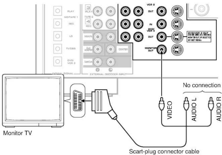
For connecting with a monitor TV that uses a 21 pin connector for input (for Europe and U.K. models)
Make a connection as figured below with a commercially available scart-plug connector cable.
■ Connecting to VIDEO AUX terminals (on the front panel)
These terminals are used to connect any video input source such as a camcorder to this unit.
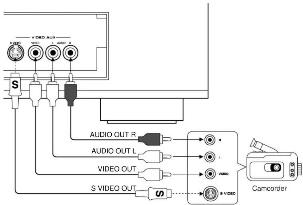
flowchart
graph TD
    A["VIDEO AUX"] --> B["S VIDEO"]
    A --> C["L AUDIO R"]
    A --> D["AUDIO OUT R"]
    A --> E["AUDIO OUT L"]
    A --> F["VIDEO OUT"]
    A --> G["S VIDEO OUT"]
    H["Camcorder"] --> I["VIDEO"]
    H --> J["S VIDEO"]
■ Connecting to digital (OPTICAL and COAXIAL) terminals
If your CD player, MD recorder, LD player, DVD player, TV/satellite tuner, etc. are equipped with coaxial or optical digital audio signal output terminals, they can be connected to this unit's COAXIAL and/or OPTICAL digital signal input terminals.
To make a connection between optical digital audio signal terminals, remove the cover from each terminal, and then connect them by using a commercially available optical fiber cable that conforms to EIAJ standards. Other cables might not function correctly.
Even if you connect an audio/video unit to the OPTICAL (or COAXIAL) terminal of this unit, you must keep the unit connected with the same named analog audio signal terminals of this unit, because digital signal cannot be recorded by a tape deck or VCR connected to only analog audio signal terminals of this unit. You can switch the selection of input signals between "digital" and "analog" easily. (See page 41 for details.)
* However, if you connect an MD recorder or DAT to this unit's OPTICAL MD/TAPE 1 PLAY and REC terminals, it can record input sources connected to this unit's OPTICAL digital signal input terminals.
Notes
- When you connect an audio/video unit to both of the digital and analog terminals of this unit, make sure to connect to both terminals of the same name.
- Be sure to attach the covers when the OPTICAL terminals are not being used, in order to protect the terminals from dust.
- All digital audio signal input terminals are applicable to the sampling frequency of 32 kHz, 44.1 kHz and 48 kHz.
- In order to make this unit perform a successful DTS-decoding, the DTS bitstream must not be altered, manipulated or corrupted in the process that it is sent from the DIGITAL OUT terminal of a unit playing back a source encoded with the DTS to a digital signal input terminal of this unit.
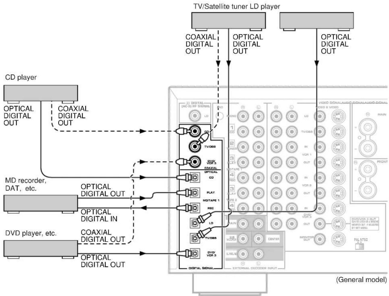
flowchart
graph TD
    A["CD player"] --> B["OPTICAL DIGITAL OUT"]
    A --> C["COAXIAL DIGITAL OUT"]
    D["MD recorder, DAT, etc."] --> E["OPTICAL DIGITAL OUT"]
    D --> F["OPTICAL DIGITAL IN"]
    G["DVD player, etc."] --> H["OPTICAL DIGITAL OUT"]
    G --> I["OPTICAL DIGITAL OUT"]
    J["TV/Satellite tuner LD player"] --> K["COAXIAL DIGITAL OUT"]
    J --> L["OPTICAL DIGITAL OUT"]
    M["VIDEO SIGNALAUDIO SIGNALAUDIO SIGNAL"] --> N["VIDEO 8 VIDEO"]
    O["VCD/VCR 3 OUT"] --> P["MONITOR OUT"]
    Q["DVD/VCR 3 OUT"] --> R["EXTERNAL DECODER INPUT"]
    S["DVD/VCR 3 OUT"] --> T["MONITOR OUT"]
    U["VIDEO VCR 3"] --> V["EXTERNAL DECODER INPUT"]
    W["VIDEO VCR 3"] --> X["EXTERNAL DECODER INPUT"]
    Y["VIDEO VCR 3"] --> Z["EXTERNAL DECODER INPUT"]
    AA["VIDEO VCR 3"] --> AB["EXTERNAL DECODER INPUT"]
    AC["VIDEO VCR 3"] --> AD["EXTERNAL DECODER INPUT"]
    AE["VIDEO VCR 3"] --> AF["EXTERNAL DECODER INPUT"]
    AG["VIDEO VCR 3"] --> AH["EXTERNAL DECODER INPUT"]
    AI["VIDEO VCR 3"] --> AJ["EXTERNAL DECODER INPUT"]
    AK["VIDEO VCR 3"] --> AL["EXTERNAL DECODER INPUT"]
    AM["VIDEO VCR 3"] --> AN["EXTERNAL DECODER INPUT"]
    AO["VIDEO VCR 3"] --> AP["EXTERNAL DECODER INPUT"]
    AQ["VIDEO VCR 3"] --> AR["EXTERNAL DECODER INPUT"]
    AS["VIDEO VCR 3"] --> AT["EXTERNAL DECODER INPUT"]
    AU["VIDEO VCR 3"] --> AV["EXTERNAL DECODER INPUT"]
    AW["VIDEO VCR 3"] --> AX["EXTERNAL DECODER INPUT"]
    AY["CD player"] --> AZ["Optical Digital Out"]
    BA["CD player"] --> BB["Optical Digital Out"]
    BC["CD player"] --> BD["Optical Digital Out"]
    BE["MD recorder, DAT, etc."] --> BF["Optical Digital OUT"]
    BG["DVD player, etc."] --> BH["Optical Digital OUT"]
    BI["DVD player, etc."] --> BJ["Optical Digital OUT"]
■ Connecting to DOLBY DIGITAL (AC-3) RF output of the LD player
If your LD player has a DOLBY DIGITAL (AC-3) RF signal output terminal, connect it to this unit's DIGITAL (AC-3) RF SIGNAL input terminal. Audio signals encoded with the Dolby Digital (AC-3) are input to this unit by this connection.
* To play back an LD source with the Dolby Digital decoded, set the input mode of LD to "AUTO" or "AC-3 RF". (Refer to page 41 for details.)
It is also necessary to connect the LD player to this unit's OPTICAL digital audio signal input terminal and/or analog audio signal input terminals regardless of the DOLBY DIGITAL (AC-3) RF signal connection, for playing back an LD source with the Dolby Pro Logic Surround or the DTS decoded, or in normal stereo (or monaural).
Note
DOLBY DIGITAL (AC-3) RF audio input signal cannot be recorded by a tape deck, MD recorder or VCR. To record an LD source, the LD player must be connected to the OPTICAL digital audio signal input terminal and/or analog audio signal input terminals of this unit.
![LD player DIGITAL OUT DOLBY DIGITAL (AC-3) RF OUTPUT AUDIO OUT VIDEO OUT S-VIDEO OUT [AC-3] RF SING AL GND PHONG 1 CO TV/OBS DVD/ VCR 3 COAXIAL OPTICAL CD PLAY MO/TAPE 1 REC LO TV/OBS DVD/ VCR 3 DIGITAL SIGNAL- EXTERNAL DECODER INPUT VIDEO SIGNALAVID SIGNALAVID SIGNAL VIDEO'S VIDEO LA TV/OBS IN VCR 1 OUT IN VCR 2 OUT IN DVD/ VCR 3 OUT MONITOR OUT PAL NTSC MAIN FRONT DVD/VCR 3 OUT CAN BE USED AS A RECORD WOMBO OUT F SELECTOR BY SET MENU (General model)](/content/2026/02/379924/images/e83cdcd58831fe2a3ea59f0ed26a72902ceef670157a5210a374835239ae6855.jpg)
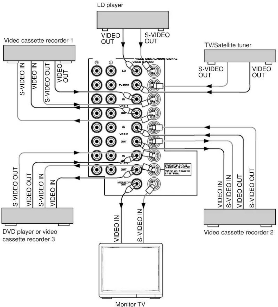
■ Connecting to S VIDEO terminals
If your video cassette recorder, LD player, etc. and your monitor are equipped with "S" (high-resolution) video terminals, connect them to this unit's S VIDEO terminals, and connect this unit's S VIDEO MONITOR OUT terminal to the "S" video input of your monitor. Otherwise, connect the composite video terminals from your video cassette recorder, LD player, etc. to the VIDEO terminals of this unit, and connect this unit's VIDEO MONITOR OUT terminal to the composite video input of your monitor.
Note
If video signals are sent to both S VIDEO input and VIDEO input terminals, the signals will be sent to their respective output terminals.
Notes about the Video superimpose
- If you watch a video source that is connected to both S VIDEO and VIDEO input terminals of this unit, signals of screen display information are output from only the S VIDEO MONITOR OUT terminal.
- When no video signal is input to either S VIDEO or VIDEO input terminals of this unit, signals of screen display information are output from both S VIDEO MONITOR OUT and VIDEO MONITOR OUT terminals with a color background.
* For China and General models, if the PAL/NTSC switch on the rear panel is set to "PAL", nothing will be output from either S VIDEO MONITOR OUT or VIDEO MONITOR OUT terminal in this case.
flowchart
graph TD
    A["LD player"] -->|VIDEO OUT| B["TV/Satellite tuner"]
    A -->|S-VIDEO OUT| B
    C["Video cassette recorder 1"] -->|S-VIDEO IN| B
    C -->|VIDEO OUT| B
    D["Video cassette recorder 2"] -->|S-VIDEO OUT| B
    D -->|VIDEO OUT| B
    E["Monitor TV"] -->|S-VIDEO IN| B
    E -->|VIDEO OUT| B
    F["DVD player or video cassette recorder 3"] -->|S-VIDEO OUT| B
    F -->|VIDEO OUT| B
    G["Monitor TV"] -->|S-VIDEO IN| B
    G -->|VIDEO OUT| B
    H["IN"] --> I["VCR 1"]
    H --> J["VCR 2"]
    H --> K["MONITOR OUT"]
    L["IN"] --> M["VCR 3"]
    L --> N["MONITOR OUT"]
    O["IN"] --> P["VCR 4"]
    Q["IN"] --> R["VCR 5"]
    S["IN"] --> T["MONITOR OUT"]
    U["IN"] --> V["VCR 6"]
    W["IN"] --> X["VCR 7"]
    Y["IN"] --> Z["MONITOR OUT"]
    AA["IN"] --> AB["VCR 8"]
    AC["IN"] --> AD["VCR 9"]
    AE["IN"] --> AF["VCR 10"]
    AG["IN"] --> AH["VCR 11"]
    AI["IN"] --> AJ["VCR 12"]
    AK["IN"] --> AL["VCR 13"]
    AM["IN"] --> AN["VCR 14"]
    AO["IN"] --> AP["VCR 15"]
    AQ["IN"] --> AR["VCR 16"]
    AS["IN"] --> AT["VCR 17"]
    AU["IN"] --> AV["VCR 18"]
    AW["IN"] --> AX["VCR 19"]
    AY["Video cassette recorder 1"] -->|S-VIDEO IN| B
    AZ["Video cassette recorder 2"] -->|S-VIDEO OUT| B
    BA["Video cassette recorder 3"] -->|S-VIDEO OUT| B
    BB["Video cassette recorder 4"] -->|S-VIDEO IN| B
    BC["Video cassette recorder 5"] -->|S-VIDEO OUT| B
    BD["Video cassette recorder 6"] -->|S-VIDEO OUT| B
    BE["Video cassette recorder 7"] -->|S-VIDEO OUT| B
    BF["Video cassette recorder 8"] -->|S-VIDEO OUT| B
    BG["Video cassette recorder 9"] -->|S-VIDEO OUT| B
    BH["Video cassette recorder 10"] -->|S-VIDEO OUT| B
■ Connecting an external sound processor, decoder (e.g. MPEG 2), amplifier, etc. to this unit
This unit is equipped with additional 6-channel audio signal input terminals (for left main, right main, center, left rear surround, right rear surround and subwoofer channels) available for inputting signals from your existing amplifier, sound processor, decoder, etc. to this unit.
To listen to a sound by reproducing signals input to these terminals, press the TAPE 2 MON/EXT. DECODER button on the front panel once or more so that "EXT. DECODER IN" appears on the display. By doing so, the signals input to these terminals are sent to the corresponding SPEAKERS terminals and OUTPUT terminals of this unit.
Note
When signals input to these terminals are selected, the digital sound field processor cannot be used.
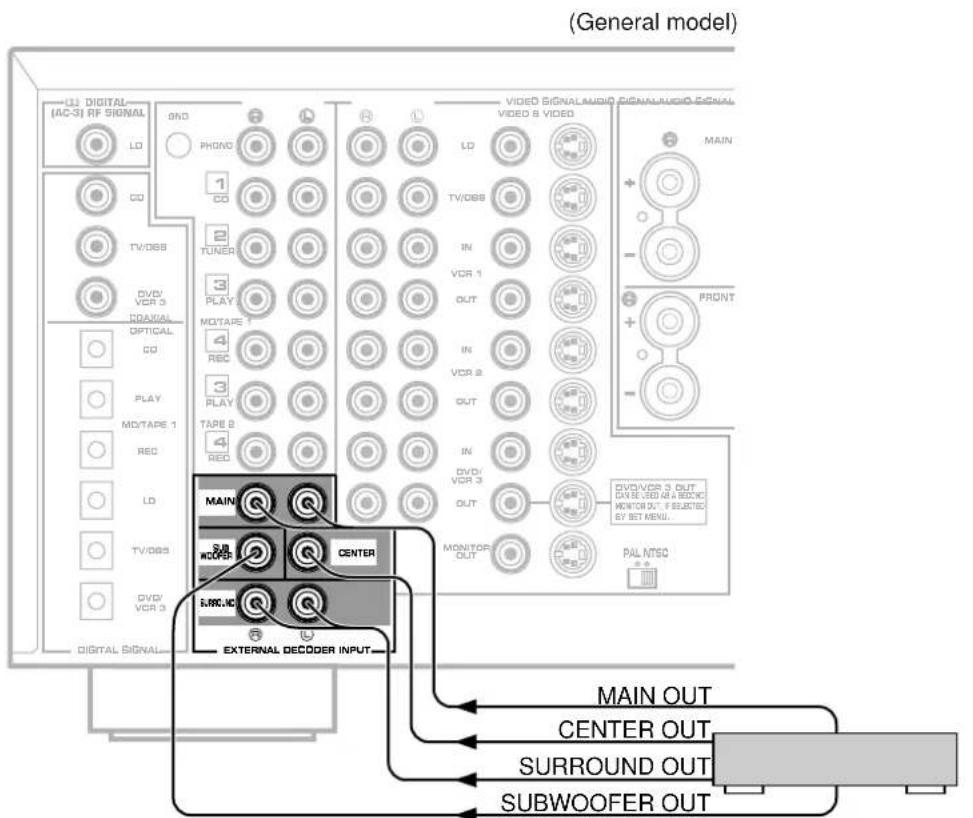
External sound processor, decoder, amplifier, etc.
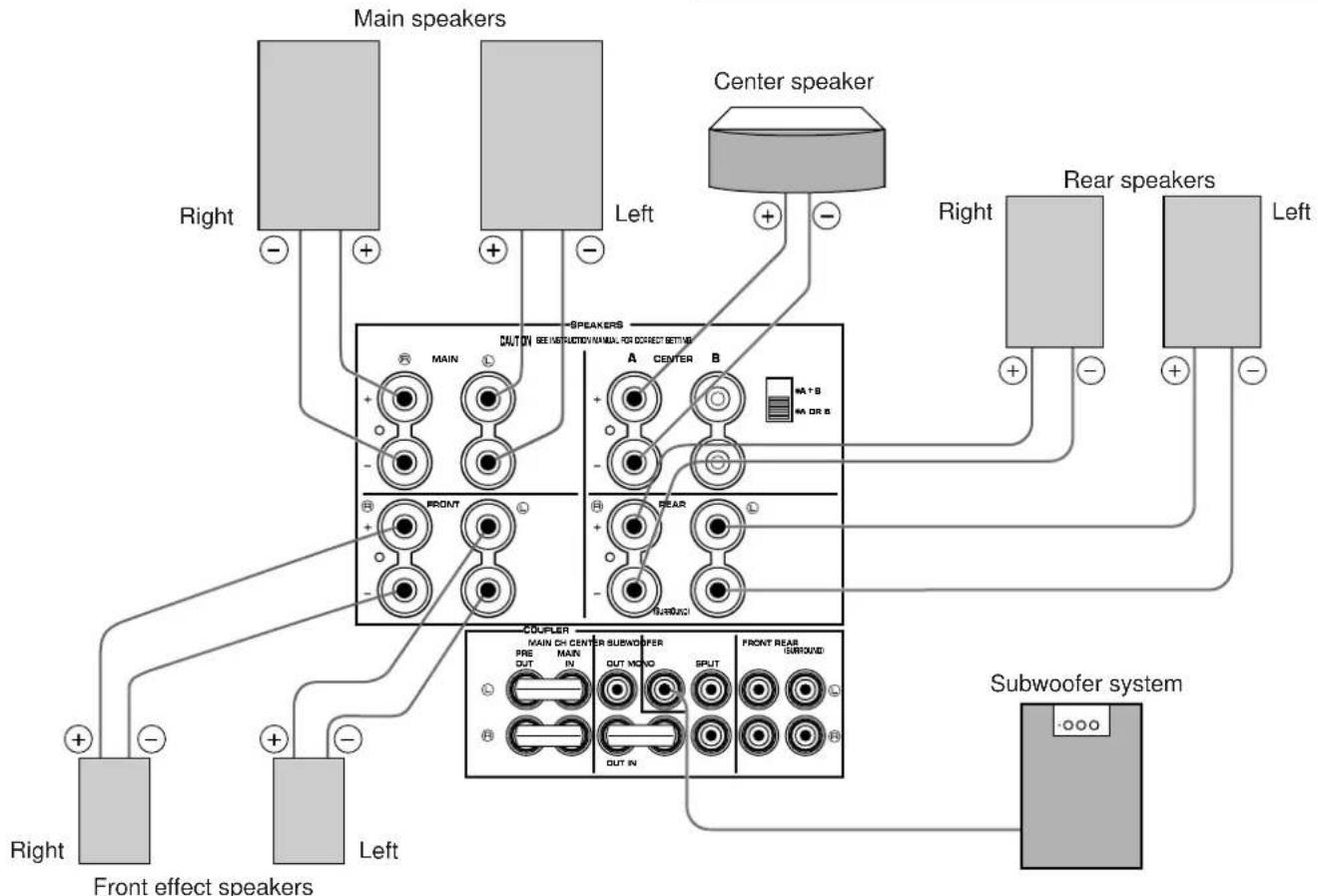
CONNECTING SPEAKERS
Use speakers with the specified impedance shown on the rear of this unit.
flowchart
graph TD
    A["Main speakers"] --> B["Center speaker"]
    B --> C["Rear speakers"]
    C --> D["Subwoofer system"]
    D --> E["Front effect speakers"]
    E --> F["Left"]
    F --> G["Right"]
    G --> H["Back to Main Speaker"]
    H --> I["Central Sounder"]
    I --> J["Central Headphones"]
    style A fill:#f9f,stroke:#333
    style B fill:#ccf,stroke:#333
    style C fill:#cfc,stroke:#333
    style D fill:#fcc,stroke:#333
    style E fill:#ffc,stroke:#333
    style F fill:#cfc,stroke:#333
    style G fill:#fcc,stroke:#333
    style H fill:#ffc,stroke:#333
    style I fill:#cfc,stroke:#333
    style J fill:#fcc,stroke:#333
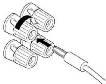
How to Connect:
Connect the SPEAKERS terminals to your speakers with wire of the proper gauge, cut as short as possible. If the connections are faulty, no sound will be heard from the speakers. Make sure that the polarity of the speaker wires is correct, that is the + and - markings are observed. If these wires are reversed, the sound will be unnatural and lack bass.
Caution
Do not let the bare speaker wires touch each other or any metal part of this unit. This could damage this unit and/or speakers.
Red: positive (+)
Black: negative (−)
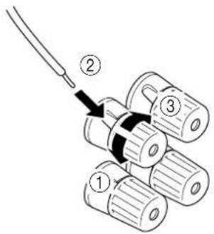
①Unscrew the knob.
②Insert the bare wire. [Remove approx. 5mm (1/4") insulation from the speaker wires.]
③Tighten the knob and secure the wire.
Banana Plug connections are also possible. Simply insert the Banana Plug connector into the corresponding terminal.
natural_image
Technical line drawing of a mechanical assembly with multiple cylindrical components and a connecting rod (no text or symbols)Note on center speaker connection:
One or two center speakers can be connected to this unit. If you cannot place the center speaker on or under the TV, it is recommended to use two center speakers and place them on both sides of the TV to orient the center sound at the center position. When using one center speaker, connect it to either the A or B terminals and set the CENTER SPEAKERS switch to "A OR B" (bottom position). When using two center speakers, connect them to the A and B terminals, and set the switch to "A + B" (top position).
If, however, you will not use a center speaker, be sure to set the function "1A. CENTER SP" in the SET MENU mode in the "NONE" position. (See page 26.)
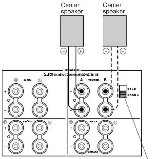
CENTER SPEAKERS switch
Note on a subwoofer connection:
You may wish to add a subwoofer to reinforce low frequencies or to output low bass sound from the subwoofer channel when reproducing discrete signals.
When using one subwoofer, connect the SUBWOOFER MONO terminal of this unit to the INPUT terminal of the subwoofer amplifier, and connect the speaker terminals of the subwoofer amplifier to the subwoofer.
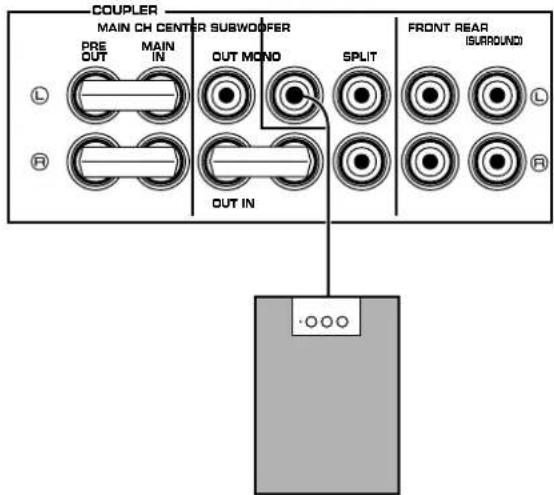
Subwoofer system
If you wish to obtain more presence in your listening room, the use of two subwoofers is recommended. To connect two subwoofers to this unit, connect one SUBWOOFER SPLIT terminal to the INPUT terminal of the amplifier driving a subwoofer, and the other SUBWOOFER SPLIT terminal to the INPUT terminal of the amplifier driving the other subwoofer, and then connect each subwoofer to the corresponding amplifier.
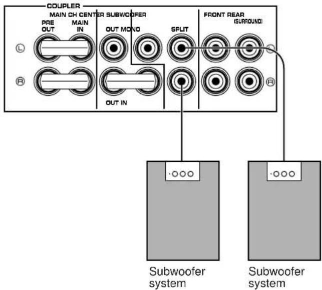
With some subwoofers, including the Yamaha Active Servo Processing Subwoofer System, the amplifier and subwoofer are in the same unit.
(Refer to page 21 for details about the SUBWOOFER MONO/SPLIT terminals.)
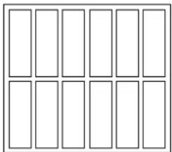
■ IMPEDANCE SELECTOR switch
Be sure to switch this only when the power to this unit is not on. Select the position whose requirements your speaker system meets.
WARNING
Do not change the IMPEDANCE SELECTOR switch setting while the power to this unit is on, otherwise this unit may be damaged.
IF THIS UNIT FAILS TO TURN ON WHEN THE STANDBY/ON SWITCH IS PRESSED;
The IMPEDANCE SELECTOR switch may not be set to either end closely. If so, set the switch to either end closely.
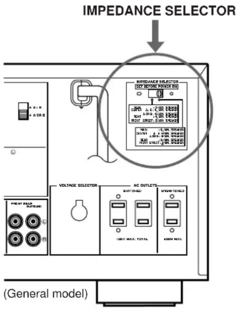
(Left position)
Rear: The impedance of each speaker must be 4 or higher.
Center: If you use two center speakers, the impedance of each speaker must be 4 or higher. If you use one center speaker, the impedance of the speaker must be 4 or higher.
Main: The impedance of each speaker must be 4 or higher.
Front effect:
The impedance of each speaker must be 6 or higher.
(Ⅱ) (Right position)
Rear: The impedance of each speaker must be 8 or higher.
Center: If you use two center speakers, the impedance of each speaker must be 4 or higher. If you use one center speaker, the impedance of the speaker must be 8 or higher.
Main: The impedance of each speaker must be 8 or higher.
Front effect:
The impedance of each speaker must be 8 or higher.
■ To drive main, center, front effect and/or rear speakers with external amplifiers
The speaker connections described on page 18 are fine for most applications. If for some reason, however, you wish to drive main, center, front effect and/or rear speakers with your existing amplifier, etc., the following terminals are available for connecting external amplifier(s) to this unit.
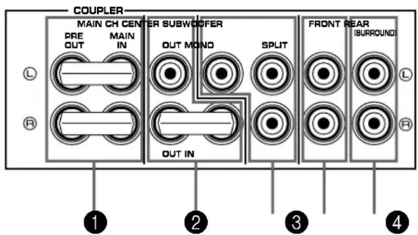
1 MAIN CH PRE OUT/MAIN IN terminals
The PRE OUT terminals are for main channel line output, and the MAIN IN terminals are for line input to the built-in main channel amplifier. The PRE OUT and MAIN IN terminals must be connected with jumper bars when the built-in amplifier is used.
However, if you drive main speakers with an external stereo power amplifier, first remove the jumper bars, and then connect the input terminals of the external amplifier (MAIN IN or AUX terminals of an amplifier or a receiver) to the PRE OUT terminals. No connection is needed to the MAIN IN terminals.
* Output signals from the PRE OUT terminals are affected by the use of BASS, TREBLE, BALANCE controls and BASS EXTENSION switch.
2 CENTER OUT/IN terminals
The CENTER OUT terminals are for center channel line output, and the CENTER IN terminal is for line input to the built-in center channel amplifier.
The lower side of CENTER OUT terminals and the CENTER IN terminal must be connected with a jumper bar when the built-in amplifier is used.
However, if you drive one or two center speakers with an external power amplifier (for each), first remove the jumper bar, and then connect the input terminal(s) of the external amplifier(s) to either or both CENTER OUT terminals. No connection is needed to the CENTER IN terminal.
3 SUBWOOFER terminals
SUBWOOFER MONO terminal
When using a subwoofer, connect its amplifier input to this terminal. Frequencies below 90 Hz distributed from the main, center and/or rear channels are output from this terminal. Signals of LFE (low frequency effect) generated when the Dolby Digital (AC-3) or the DTS is decoded are also output if they are assigned to this terminal.
SUBWOOFER SPLIT terminals
When using two subwoofers, connect their amplifier inputs to these terminals. Low bass signals that are output from the SUBWOOFER MONO terminal are also output from these terminals. However, signals from the left main and left rear channels are output to the SPLIT L terminal, and signals from the right main and right rear channels are to the SPLIT R terminal separately.
4 FRONT terminals
These terminals are for front effect channel line output. There is no connection to these terminals when you use the built-in amplifier.
However, if you drive front effect speakers with an external stereo power amplifier, connect the input terminals of the external amplifier (MAIN IN or AUX terminals of an amplifier or a receiver) to these terminals.
5 REAR (SURROUND) terminals
These terminals are for rear channel line output. There is no connection to these terminals when you use the built-in amplifier.
However, if you drive rear speakers with an external stereo power amplifier, connect the input terminals of the external amplifier (MAIN IN or AUX terminals of an amplifier or a receiver) to these terminals.
Notes
- Output level of signals from all of these terminals are adjusted by the use of VOLUME control on the front panel or MASTER VOLUME keys on the remote control transmitter.
- If an external power amplifier is connected to the FRONT or REAR output terminals, the corresponding internal amplifier will be turned off and no output will be available at the SPEAKERS terminals.
PLUGGING IN THIS UNIT
• After completing all connections, plug the AC power cord into a convenient AC outlet.
- Unplug the AC power cord from the AC outlet if this unit is not to be used for a long period of time.
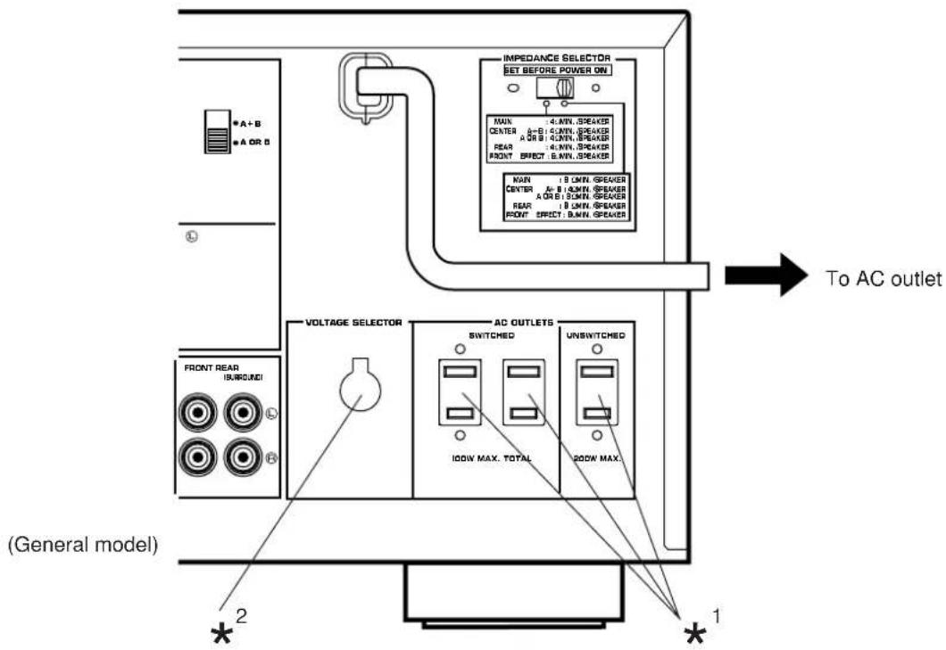
^* AC OUTLET(S)
(U.S.A., Canada, China and General models) 2 SWITCHED OUTLETS 1 UNSWITCHED OUTLET
(Europe, U.K. and Australia models) 1 SWITCHED OUTLET
Use these to connect the power cords from your components to this unit.
The power to the SWITCHED outlets is controlled by this unit's STANDBY/ON switch or the provided remote control transmitter's SYSTEM POWER ON and STANDBY keys.
These outlets will supply power to any connected unit whenever this unit is turned on.
The maximum power (total power consumption of components) that can be connected to the SWITCHED AC OUTLET(S) is as follows.
• U.S.A. model: 120W
• Except U.S.A. model: 100W
The power to the UNSWITCHED outlet is not controlled by this unit's STANDBY/ON switch or the provided remote control transmitter's SYSTEM POWER ON and STANDBY keys. This outlet will supply power to the connected unit even if this unit is in the standby mode.
The maximum power (total power consumption of components) that can be connected to the UNSWITCHED AC OUTLET is as follows.
• U.S.A. and Canada models: 180W
• China and General models: 200W
^*^2 Voltage Selector (China and General Models only)
The voltage selector on the rear panel of this unit must be set for your local main voltage BEFORE plugging into the AC main supply.
Voltages are 110/120/220/240 V AC, 50/60 Hz.
CONTROLS AND THEIR FUNCTIONS
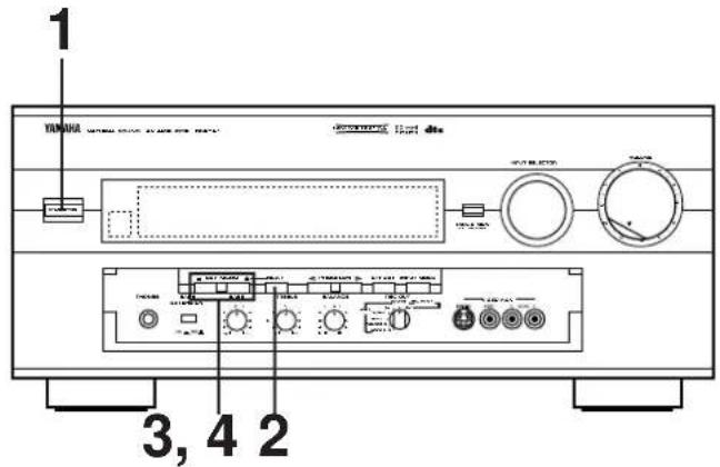
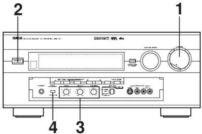
FRONT PANEL
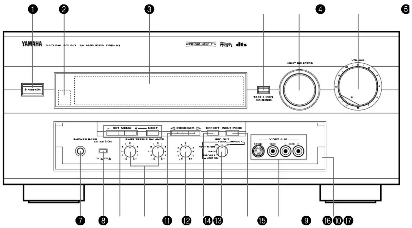
1 STANDBY/ON switch
Press this switch to turn the power to this unit on. Press it again to turn this unit into the standby mode.
* When you press this switch to turn the power on, you will hear a click and a sound of the built-in fan rotating for a moment.
Standby mode
In this state, this unit consumes a very small quantity of power to receive infrared-signals from the remote control transmitter.
2 Remote control sensor
Receives signals from the remote control transmitter.
③ Display panel
Shows various information. (For details, refer to page 25.)
4 TAPE 2 MON/EXT. DECODER button
When this button is pressed once or more so that "TAPE2 MONITOR ON" appears on the display, sound source played on the unit connected to the TAPE 2 PLAY/REC AUDIO SIGNAL terminals on the rear of this unit is selected as the input source taking priority of the INPUT SELECTOR's setting. When this button is pressed once or more so that "EXT. DECODER IN" appears on the display, sound signals input to the EXTERNAL DECODER INPUT terminals on the rear of this unit is selected as the input source taking priority of the INPUT SELECTOR's setting.
When this button is pressed once or more so that the display returns to a normal display mode, the above input sources are canceled.
5 INPUT SELECTOR
Selects the input source that you want to listen to (and watch). The selected source is shown on the display.
6 Master VOLUME control
Simultaneously controls volume level at all outputs: front effect, main, rear, center, and subwoofer. (This does not affect REC OUT level.)
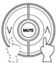
* When the volume is decreased by pressing the MUTE key on the remote control transmitter, the indicator on the master VOLUME control flashes on and off.
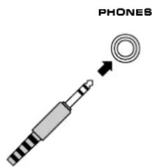
7 PHONES jack
Plug in headphones here for private listening. Sound signals from the main channels only are output here. However, if the Dolby Digital (AC-3) or the DTS is decoded, signals at all channels are distributed to the main channels and output here.
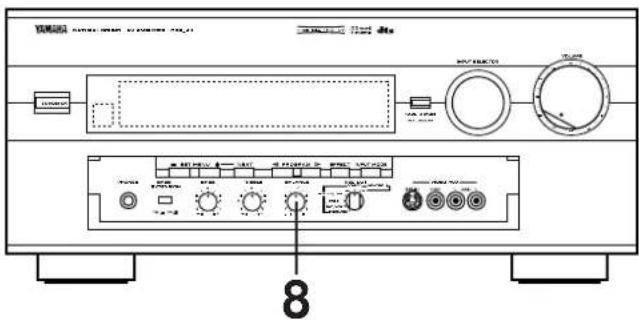
8 BASS EXTENSION switch
When this switch is pressed inward (ON), boosts bass frequency response at the main left and main right channels while maintaining overall tonal balance. If you do not have a subwoofer, the use of this switch will be effective to reinforce the bass frequencies.
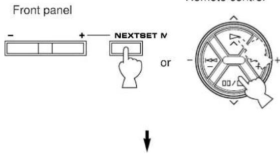
9 SET MENU -/+ button
Performs setting changes and adjustments for functions selected by pressing the NEXT button.
NEXT button
Selects functions in the SET MENU mode whenever pressed.
10 BASS and TREBLE controls
Adjust low and high frequency response respectively for the left main, right main and center channels only.
11 PROGRAM selector button
Sequentially selects the digital sound field processing programs in the on direction.
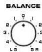
12 BALANCE control
This control is effective only for the sound from the main speakers.
This control adjusts the balance of the output volume to the left and right main speakers to compensate for sound imbalance caused by speaker location or listening room conditions.
13 EFFECT button
Switches on and off the output from the center, rear and front effect speakers. When switched to off, the sound becomes normal 2-channels.
* Even if the output from the center, rear and front effect speakers is off, when the Dolby Digital (AC-3) or the DTS is decoded, signals at all channels are distributed to the main channels and output from the main speakers.
14 REC OUT selector
Selects the source to be recorded to an MD recorder (or tape deck 1) or VCR 1 independently of the setting of the INPUT SELECTOR. However, when set to the SOURCE position, the setting of the INPUT SELECTOR decides the source to be recorded to an MD recorder (or tape deck) or VCR.
15 INPUT MODE button
Switches the mode of selecting input signals between "AUTO", "DTS" and "ANALOG" modes for sources that input two or more types of signals to this unit. (Refer to page 41 for details.) * For LD source, this switches among "AUTO", "AC-3 RF", "DTS", "DIGITAL" and "ANALOG" modes.
16 VIDEO AUX terminals
Connect an auxiliary video or audio input source unit such as a camcorder to these terminals. If the connected video unit has a S video output terminal, connect it to the S VIDEO terminal to obtain a high resolution picture. The source connected to these terminals can be selected by the INPUT SELECTOR and REC OUT selector.
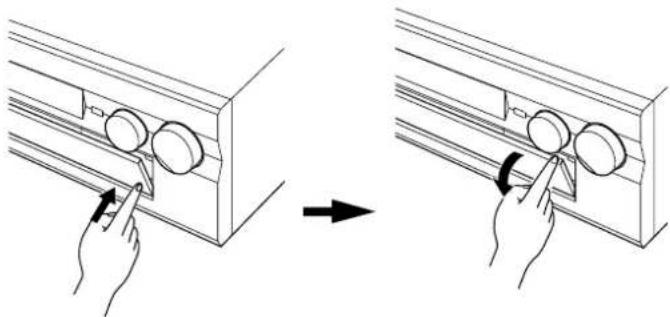
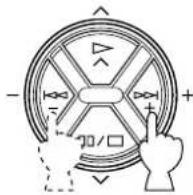
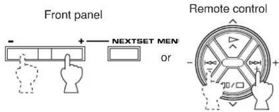
17 Control door
When it is not necessary to operate controls inside the control door, close the door.
To open the door
natural_image
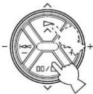
Diagram showing two-step installation of a wall-mounted device, with hand positioning and rotation arrows (no text or symbols)To close the door

natural_image
Line drawing of a hand inserting a device into a rack with buttons (no text or symbols)
flowchart
graph TD
    A["dts dts"] --> B["Digital"]
    A --> C["PRO LOGIC"]
    A --> D["DSP"]
    A --> E["Digital Source AC-3 DTS PCM"]
    F["MOVIE THEATER 1 DGTL Spectacle"] --> G["TV/DBS"]
    F --> H["VCR 1"]
    F --> I["VCR 2"]
    F --> J["DV0/VCR 3"]
    F --> K["V-AUX"]
    F --> L["SLEEP"]
    F --> M["LD"]
    F --> N["MO/TAPE 1"]
    F --> O["TUNER"]
    F --> P["CD"]
    F --> Q["PHONO"]
    F --> R["TAPE 2 MON"]
① dt indicators
When the built-in DTS decoder is on, either dts indicator lights up. Red "dts" indicator lights up when playing a compact disc or laserdisc encoded with the DTS. Orange "dts" indicator lights up when playing a DVD encoded with the DTS.
* On a DVD/LD combi-player, if you play a laserdisc encoded with the DTS after playing a Video-CD, DVD, etc., the orange "dts" indicator may light up.
2 Multi-information display
Shows the currently selected DSP program, or information for several adjustments or setting changes made on this unit.
3 Input source indicators
Show the currently selected input source by the arrow-shaped cursor.
4 DIGITAL and PBO LOGIC indicators
“ DIGITAL” lights up when the built-in Dolby Digital (AC-3) Decoder is on and the signals of selected source encoded with the Dolby Digital (AC-3) is not in 2-channels.
“DRO LOGIC” lights up when the built-in Dolby Pro Logic Surround Decoder is on.
5 DSP indicator
"DSP" lights up when the built-in digital sound field processor is on.
6 Digital audio input signal indicators
These indicators show the type of digital signal currently input to this unit.
When PCM digital audio signals are input to this unit, "PCM" lights up.
When digital audio signals encoded with the Dolby Digital (AC-3) are input to this unit, "AC-3" lights up.
When digital audio signals encoded with the DTS are input to this unit, "DTS" lights up.
7 SLEEP indicator
Lights up while the built-in SLEEP timer is functioning.
8 TAPE 2 MON indicator
Lights up when the tape deck (or MD recorder etc.) connected to the TAPE 2 PLAY/REC AUDIO SIGNAL terminals on the rear of this unit is selected as the input source by pressing the TAPE 2 MON/EXT. DECODER button.
ADJUSTMENTS BEFORE USING THIS UNIT
SELECTING THE OUTPUT MODES SUITABLE FOR YOUR SPEAKER SYSTEM (IN THE "SET MENU" MODE)
This unit provides you with the following functions to distribute respective output signals to suitable speakers in your audio system. When speaker connections are all completed, select a proper position on each function to make the best use of your speaker system.
* For details about the SET MENU mode, refer to pages 32 to 38.
1. SPEAKER SET
1A. CENTER SP
1B. REAR SP
1C. MAIN SP
1D. LFE/BASS OUT
1E. FRONT MIX
1F. MAIN LEVEL
■ DESCRIPTION OF EACH FUNCTION
1A. CENTER SP
Choices: LARGE (LRG)/SMALL (SML)/NONE Preset position: LRG
LRG: Select this position when your center speaker is approximately the same size as the main speakers.
SML: Select this position when you use a center speaker that is smaller than the main speakers. In this position, low bass signals (below 90 Hz) at the center channel are output from the SUBWOOFER terminals (or the main speakers if the MAIN position is selected on "1D. LFE/BASS OUT").
NONE: Select this position when you do not have a center speaker. The center channel sound will be output from the left and right main speakers.
1B. REAR SP
Choices: LARGE/SMALL Preset position: LARGE
LARGE: Select this position if your rear speakers have a high ability for bass reproduction, or a subwoofer is connected to the rear speaker in parallel. In this position, full range signals are output from the rear speakers.
SMALL: Select this position if your rear speakers do not have a high ability for bass reproduction. In this position, low bass signals (below 90 Hz) at the rear channels are output from the SUBWOOFER terminals (or the main speakers if the MAIN position is selected on "1D. LFE/BASS OUT").
1C. MAIN SP
Choices: LARGE/SMALL
Preset position: LARGE
LARGE: Select this position if your main speakers have a high ability for bass reproduction. In this position, full range signals present at the main channels are output from the main speakers.
SMALL: Select this position if your main speakers do not have a high ability for bass reproduction. However, if your system does not include a subwoofer, do not select this position. In this position, low bass signals (below 90 Hz) at the main channels are output from the SUBWOOFER terminals (if the SW or BOTH position is selected on "1D. LFE/BASS OUT").
1D. LFE/BASS OUT
Choices: SW/MAIN/BOTH
Preset position: SW
MAIN: Select this position if your system does not include a subwoofer. In this position, full range signals present at the main channels, signals from the LFE channel and other low bass signals that are selected on "1A. CENTER SP" to "1C. MAIN SP" to be distributed from other channels are output from the main speakers.
SW/BOTH:
Select either the SW or BOTH position if your system includes a subwoofer. In either position, signals at LFE channel and other low bass signals that are selected on "1A. CENTER SP" to "1C. MAIN SP" to be distributed from other channels are output from the SUBWOOFER terminals. When the LARGE position is selected on "1C. MAIN SP", in the SW position, no signal is distributed from the main channels to the SUBWOOFER terminals, however in the BOTH position, low bass signals from the main channels are output to both of the main speakers and the SUBWOOFER terminals.
1E. FRONT MIX
Choices: OFF-7ch/ON-5ch
Preset position: OFF-7ch
OFF-7ch: Select this position if your speaker system includes a pair of front effect speakers.
ON-5ch: Select this position if your speaker system does not include a pair of front effect speakers. Sound signals at the left and right front effect channels are distributed to the left and right main channels respectively, and output from the main speakers.
1F. MAIN LEVEL
Choices: Normal/-10dB
Preset position: Normal
Normal: Normally, select this position.
-10dB: Select this position if the volume levels to the center, rear and/or front effect speakers are lower than the level to the main speakers even though they are adjusted to maximum. The volume level to the main speakers are decreased by 10 dB, so you can adjust the speaker output level balance properly.
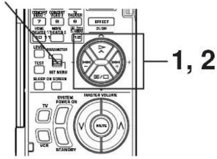
■ METHOD OF CHANGING SELECTIONS
Operations should be made watching information on this unit's display panel or the monitor screen.

If you will use the remote control transmitter, set the PARAMETER/SET MENU switch to the SET MENU position on the remote control transmitter.
Note: Be sure to use the remote control transmitter with the lid open.

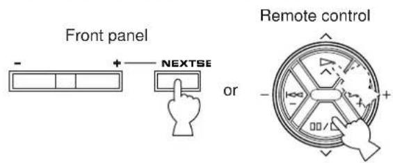
2 Select the title "1. SPEAKER SET" by pressing the button figured below once or more (so that the title appears on the display).
- SPEAKER SET TWOSS B=LO VER 1 NOTCAPS 1 VER 2 TUNCH OVER 3 CO VAUX PHONG
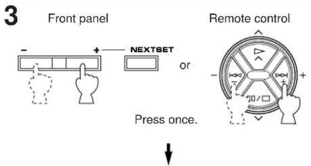
1A. CENTER SP ▶ LRG SML NONE TV088 VCR 1 VCR 2 DVCHOR 3 V AUX ▶ LD MOTARE 1 TUMER CO PHONO
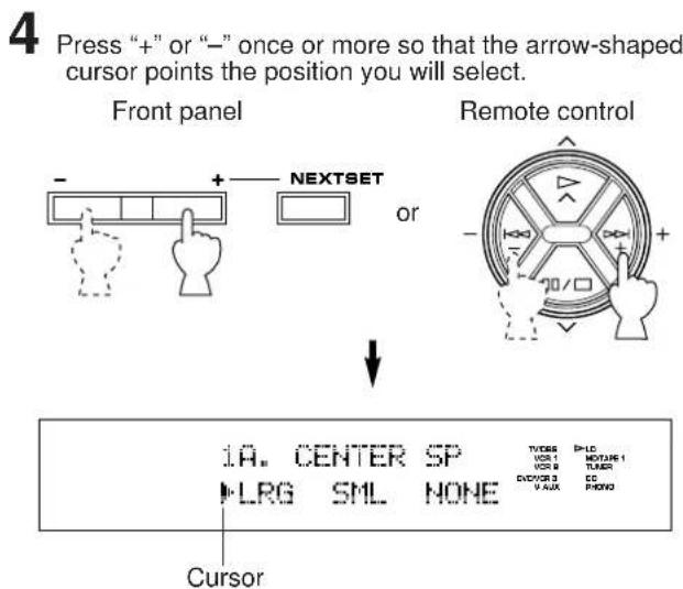
5 In the same way, select a proper position on "1B. REAR SP", "1C. MAIN SP", "1D. LFE/BASS OUT", "1E. FRONT MIX" and/or "1F. MAIN LEVEL". First select the title of function by following step 2, and then select a proper position by following step 4.
SPEAKER BALANCE ADJUSTMENT
This procedure lets you adjust the sound output level balance between the main, center rear and front effect speakers using the built-in test tone generator. When this adjustment is performed, the sound output level heard at the listening position will be the same from each speaker. This is important for the best performance of the digital sound field processor, the Dolby Digital (AC-3) decoder, the Dolby Pro Logic Surround decoder and the DTS decoder.
The adjustment of each speaker output level should be done at your listening position with the remote control transmitter. Otherwise, the result may not be satisfactory.
Note: Be sure to use the remote control transmitter with the lid open.
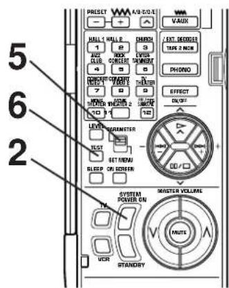
1
Set to the "∞" position.
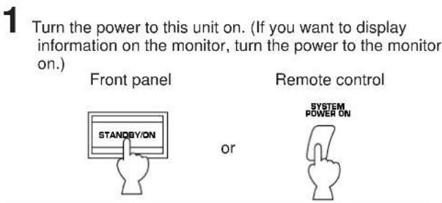
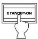
2
Turn the power on.
Front panel
Remote control
or

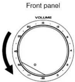
3
Front panel


Set to the "0" position.
4
Front panel
BASS EXTENSION
Set to the "OFF ( )
5
Set the PARAMETER/SET MENU switch on the remote control transmitter to the PARAMETER position.
Remote control
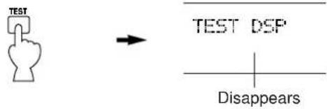
6
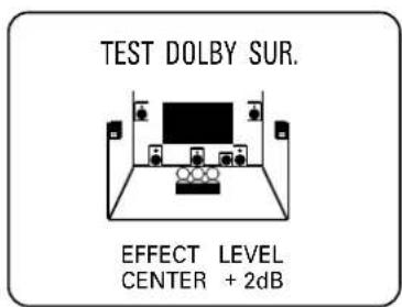
Press the TEST key on the remote control transmitter so that "TEST DOLBY SUR." appears on the display to enter test mode.
Remote control


TEST DOLEY SUR.
CONTINUED
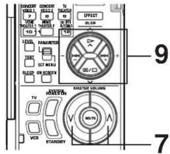
7 Turn up the volume.
Remote control
You will hear a test tone (like pink noise) from the left main speaker, then the center speaker, then the right main speaker, then the right rear speaker, and then the left rear speaker, for about 2.5 seconds each. The display changes as shown below.
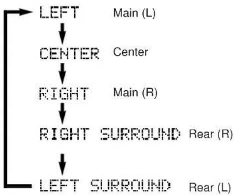
flowchart
graph TD
    A["LEFT"] --> B["CENTER"]
    B --> C["RIGHT"]
    C --> D["RIGHT SURROUND"]
    D --> E["LEFT SURROUND"]
    style A fill:#f9f,stroke:#333
    style B fill:#ccf,stroke:#333
    style C fill:#cfc,stroke:#333
    style D fill:#fcc,stroke:#333
    style E fill:#cff,stroke:#333
* The state of test tone output is also shown on the monitor screen by an image of audio listening room. This is convenient for adjusting each speaker level.
* If the function "1A. CENTER SP" in the SET MENU mode is set in the "NONE" position, you will hear the center channel test tone from the left and right main speakers.
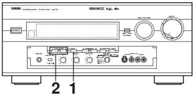
8 Adjust the BALANCE control so that the effect sound output level of the left main speaker and the right main speaker are the same.
Front panel
9 Adjust the sound output levels of the center speaker and the rear speakers so that they become almost as same as that of the main speakers.
How to adjust:
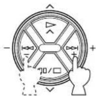
Pressing the + or - key adjusts the level to the speaker (except the main speakers) currently outputting the test tone.
* Pressing the + key raises and the - key lowers the level.
* While adjusting, the test tone is fixed on the selected speaker.
Remote control
If desired, you can select a speaker to output the test tone by pressing the or key once or more so that "CENTER", "RIGHT SURROUND" or "LEFT SURROUND" appears on the display.
* While holding the or key-pressed, the test tone is fixed on the selected speaker.
* "CENTER" shows the center speaker is selected, "RIGHT SURROUND" shows the right rear speaker, and "LEFT SURROUND" shows the left rear speaker.
* The output level of the selected speaker can be adjusted by the + or - key.
Remote control
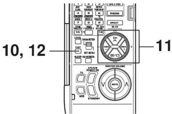
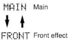
10
For the front effect speaker level adjustment, press the TEST key on the remote control transmitter again so that "TEST DSP" appears on the display.
Remote control
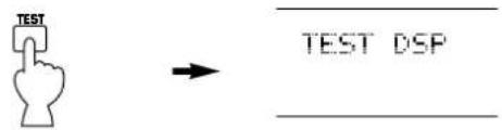
A calibration signal should be heard from the main speakers and the front effect speakers in turn.
11
Adjust the front effect speaker level by pressing the
- or - key so that it becomes almost as same as that of the main speakers.
* While adjusting, the test tone is fixed on the front effect speaker.
Remote control
* Pressing the or key makes the test tone fix on the left front effect speaker and the right front effect speaker respectively. This is helpful for you to check that each speaker is correctly connected to this unit.
12
When the adjustment is finished, press the TEST key once again to cancel the test tone.
Remote control
Notes
- Once you have completed these adjustments, you can adjust whole sound level on your audio system by using the VOLUME control (or the MASTER VOLUME keys on the remote control transmitter) only.
- If you use external power amplifiers, you may also use their volume controls to achieve proper balance.
- If the function "1A. CENTER SP" in the SET MENU mode is set in the "NONE" position, in step 9, the sound output level of the center speaker cannot be adjusted. This is because in this mode, the center sound is automatically output from the left and right main speakers.
- If there is insufficient sound output from the center and rear speakers, you may decrease the main speaker output level by setting the function "1F. MAIN LEVEL" in the SET MENU mode in the "-10dB" position.
ADJUSTMENTS IN THE "SET MENU" MODE
The following twelve types of functions maximize the performance of your system and expand your enjoyment for audio listening and video watching.
- SPEAKER SET
1A. CENTER SP
1B. REAR SP
1C. MAIN SP
1D. LFE/BASS OUT
1E. FRONT MIX
1F. MAIN LEVEL -
LOW FREQ. TEST
-
DLBY DGTL SET
3A. LFE LEVEL
3B. D-RANGE - DTS SET
4A. LFE LEVEL - CENTER DELAY
-
CENTER GEQ
-
CINEMA EQ
- PARAMETER INI
- MEMORY GUARD
- VCR3 VIDEO
- INPUT MODE
- DIMMER
■ METHOD OF SETTING CHANGE AND ADJUSTMENT
PARAMETER/SET MENU
Operations should be made watching information on this unit's display panel or the monitor screen. If you want to display information on the monitor, turn on the power to the monitor.
The use of the remote control transmitter is recommended for easier operation.
When using the remote control transmitter, set the PARAMETER/SET MENU switch to the SET MENU position on the remote control transmitter.
Note: Be sure to use the remote control transmitter with the lid open.
1 Press once or more until the title of function on which you will make a change appears on the display.
2 Select any desired position or edit parameters on the function.
3 Repeat step 1 and 2 to make a setting change or adjustment on any other function.
Note
A detailed adjusting method by using the remote control transmitter's keys is described for each function on pages 33 to 38. When you make an adjustment on the front panel, note the following.
- +/- keys on the remote control transmitter are identical with the SET MENU +/- button on the front panel.
- √ key on the remote control transmitter is identical with the NEXT button on the front panel.
In addition, note that the key on the remote control transmitter can be used to change selections in the order reverse to the key.
1. SPEAKER SET (Selecting the output modes suitable for your speaker system)
Refer to pages 26 to 28 for details. (Once you have selected proper modes, you do not have to make a setting change until any alteration is made in your speaker system.)
2. LOW FREQ. TEST (Adjusting subwoofer level by using the test tone)
The internal low frequency test tone generator is useful for adjusting subwoofer level to make the subwoofer sound match the sound of other speakers in your audio system.
Operating procedure
- After selecting this function (title) in step 1 on page 32, press the + or - key to display the mode for adjustment.
- Press the key so that the arrow points to "TEST TONE . . . OFF". Next press the + or - key to switch to the "ON" position. The test tone is heard from the selected speaker(s).
- Press the key so that the arrow points to "OUTPUT · · ·". Next press the + or - key to select the speaker whose sound you want to compare with the subwoofer sound. The test tone is output from the selected speaker.
* Adjust the MASTER VOLUME keys so that the test tone can be heard at your desired listening level.
* If "SUBWOOFER" is selected, the test tone below 90 Hz is output from the subwoofer.
* The test tone will not be necessarily output from only the selected speaker(s). The output mode of the test tone depends on the settings on "1. SPEAKER SET" in the SET MENU mode. * Even if a source is being played back, the test tone is output instead of the source sounds.
- Press the key so that the arrow points to "FREQ. . . . . . . 88 Hz". To confirm that the subwoofer sound matches the sound of other speakers, change the frequency of test tone one by one by pressing the + or - key. (Frequency can be changed from 35 Hz to 250 Hz, and last, all range (35–250 Hz) of frequencies are output.) Adjust subwoofer level with the control on the subwoofer so that the subwoofer sound matches the sound of other speakers in any range of low frequencies.
Note
This low frequency test tone can also be applied to check the bass response in your room. For the best bass condition, bass sound must be heard definitely at any position in your room. If not, change the setting of subwoofer or furniture in your room.
3. DLBY DGTL (DOLBY DIGITAL) SET
Adjusting method
After selecting the title "3. DLBY DGTL SET" in step 1 on page 32, press the + or - key to display the title "3A. LFE LEVEL". To select the title "3B. D-RANGE", press the √ key. (To select the title "3A. LFE LEVEL" again, press the key.) Then make a setting change or adjustment with the + or - key.
3A. LFE LEVEL (Adjusting the output level at the LFE (low frequency effect) channel)
• Control range: -20 dB to 0 dB
Preset value: 0 dB
- This adjustment is effective only when the Dolby Digital (AC-3) is decoded and the signals of selected source encoded with the Dolby Digital (AC-3) contain LFE signals.
Adjusts the output level at the LFE (low frequency effect) channel. If the LFE signals are mixed with signals at other channels to output them from the same speakers, the ratio of LFE signal level to the level of other signals are adjusted. (Refer to page 5 for details about the LFE channel.)
3B. D-RANGE (Adjusting dynamic range)
• Choices: MAX/STD/MIN Preset position: MAX
• This adjustment is effective only when the Dolby Digital (AC-3) is decoded.
MAX: "Dynamic range" is the difference between the maximum level and the minimum level of sounds. Sounds on a movie originally designed for movie theaters feature very wide dynamic range. Dolby Digital (AC-3) technology can bring the original sound track into a home audio format with this wide dynamic range unchanged. In this position, a source encoded with the Dolby Digital (AC-3) is reproduced in the original sound track's wide dynamic range providing you with powerful sounds like a movie theater. Selecting this position will be more ideal if you can listen to a source in a high output level in a room specially soundproofed for audio/video enjoyment.
STD (Standard):
Powerful sounds of extremely wide dynamic range are not always suitable for home use. Depending upon the condition of your listening environment, it may not be possible to increase the sound output level as high as a movie theater. However, in a level suitable for listening in your room, the low level parts of source sound cannot be heard well because they will be lost among noises in your environment.
Dolby Digital (AC-3) technology also made it possible to reduce an original sound track's dynamic range for a home audio format by "compressing" the data of sound.
In this position, a source encoded with the Dolby Digital (AC-3) is reproduced in the “compressed” dynamic range of the source suitable for low level listening.
If you desire, you can adjust the dynamic range manually only when the STD position is selected.
■ H-LEVEL CUT (High Level Cut Scale)
Control range: 0.0 to 1.0 Preset value: 1.0
Adjusts the dynamic range of high level signals of source. The larger the value, the more the range is reduced. The smaller the value, the range is more widened.
■ L-LEVEL BST (Low Level Boost Scale)
Control range: 0.0 to 1.0 Preset value: 1.0
Adjusts the dynamic range of low level signals of source. The larger the value, the more the range is widened. The smaller the value, the range is more reduced.
Adjusting method
Select the title H-LEVEL CUT or L-LEVEL BST by pressing the or key and adjust its value by pressing the + or - key.
MIN: In this position, dynamic range is more reduced than in the STD position. Selecting this position will be effective when you must listen to a source in extremely low level.
* In this position, it may happen that sound is output faintly or not output normally depending on a source. In that case, select the MAX or STD position.
4. DTS SET
Adjusting method
After selecting the title "4. DTS SET" in step 1 on page 32, press the + or - key to display the title "4A. LFE LEVEL". Then adjust its level with the + or - key.
4A. LFE LEVEL (Adjusting the output level at the LFE (low frequency effect) channel)
• Control range: -10 dB to 10 dB
Preset value: 0 dB
- This adjustment is effective only when the DTS is decoded and the signals of selected source encoded with the DTS contain LFE signals.
Adjusts the output level at the LFE (low frequency effect) channel. If the LFE signals are mixed with signals at other channels to output them from the same speakers, the ratio of LFE signal level to the level of other signals is adjusted. (Refer to page 6 for details about the LFE channel.)
5. CENTER DELAY (Adjusting the delay of center sounds (dialog etc.))
• Control range: 0 ms to 5 ms (in 1 ms step)
Preset value: 0 ms
- This adjustment is effective only when the Dolby Digital (AC-3) or the DTS is decoded and the signals of selected source encoded with the Dolby Digital (AC-3) or the DTS contain center channel signals.
Adjusts the delay between the main sounds (at the main channels) and dialog etc. (at the center channel). The larger the value, the later the dialog etc. is generated. In your audio system, the distance from the center speaker to your listening position may be shorter than the distance from the left or right main speaker to your listening position. In that case, sounds from the left main, center and right main speakers can reach your listening position at the same time by delaying the sound from the center speaker.
6. CENTER GEQ (Adjusting the Center Channel Graphic Equalizer)
The built-in five band graphic equalizer is used to tailor, over a ±6 dB range, the overall output frequency response of the center channel. The five bands cover the complete audible sound spectrum and are centered on 100 Hz, 300 Hz, 1 kHz, 3 kHz and 10 kHz frequencies. Adjustment should be done to each frequency individually.
Adjusting method
After selecting the function (title) in step 1 on page 32, press the + or - key to display the condition of the equalizer. Then select a frequency with the or key and adjust its level with the + or - key.
* Adjustment can be made by monitoring sounds using the test tone. To use the test tone, press the TEST key so that "TEST DOLBY SUR." appears on the display before making adjustment. The test tone is output from the center speaker(s).
7. CINEMA EQ (Adjusting the tonal balance of speakers)
It is difficult to balance tonal quality of the main, center, front effect and rear effect speakers, because they may be different in type and size, and their setting positions and heights are also different. The built-in CINEMA Equalizer enables you to balance tonal quality of the speakers easily by adjusting tonal quality of the main/center, front effect and rear effect channels individually.
This is also useful to compensate for loss of tonal response of the main and center speakers when these speakers are placed behind the projection screen (if you use a projector in place of a TV).
The CINEMA Equalizer consists of the High-shelving equalizer (HIGH) and the Parametric equalizer (PEQ). The High-shelving equalizer changes high frequency characteristics smoothly, and the Parametric equalizer boosts or cuts any selected frequency smoothly.
Adjusting method
- After selecting this function (title) in step 1 on page 32, press the + or - key.
- Select the channels on which you will make adjustments by pressing the or key so that the arrow points the corresponding title.
L, C, R .... Left main, center and right main channels FRNT EFCT .... Front effect channels REAR EFCT .... Rear channels
-
Press the + or - key to turn the equalizer for the selected channels to "ON".
-
Press the key repeatedly until the title of adjusting mode (7A. L,C,R EQ/7B. FRNT EFCT EQ/7C. REAR EFCT EQ) for the channels on which you will make adjustments is displayed. * The adjusting mode will not be displayed for the channels that are set to "OFF" in step 2.
- Make adjustments for the selected channels. Select the item with the or key and change the value with the + or - key.
HIGH: FRQ...... Selects a turnover frequency of the High-shelving equalizer.
GAIN ....Adjusts the maximum equalizing level.
PEQ: FRQ...... Selects a frequency you will boost or cut.
GAIN ....Adjusts the equalizing level on the selected frequency.
* Adjustment can be made by monitoring sounds using the test tone. To use the test tone, press the TEST key so that "TEST DOLBY SUR." or "TEST DSP" appears on the display. The test tone is fixed on the channels on which you make an adjustment and output from the corresponding speakers.
It is recommended to make these adjustments together with the tonal quality adjustment of the center speaker on the function "6. CENTER GEQ".
Note
Excessive increase of the GAIN level may cause an overload. It is recommended to adjust the GAIN level so that it becomes lower than the preset value.
■ Preset value of the CINEMA Equalizer
L, C, R EQ
HIGH: FRQ 12.7 kHz
GAIN -3 dB
PEQ: FRQ 12.7 kHz
GAIN -4 dB
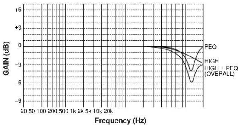
FRONT, REAR EFCT EQ
HIGH: FRQ 12.7 kHz
GAIN 0 dB
PEQ: FRQ 8.0 kHz
GAIN ...... -3 dB

line
| Frequency (Hz) | GAIN (dB) | | -------------- | --------- | | 20 | 0 | | 50 | 0 | | 100 | 0 | | 200 | 0 | | 500 | 0 | | 1k | 0 | | 2k | 0 | | 5k | 0 | | 10k | 0 | | 20k | 0 | | High | 0 | | PEQ | -3 |■ Frequency characteristics
The following curves show frequency characteristics when the High-shelving equalizer (HIGH) is adjusted at the indicated values.
HIGH: FRQ 1.0 kHz
GAIN ....+6 dB to -9 dB
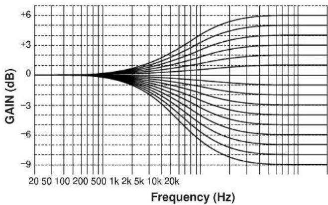
HIGH: FRQ .... 1.0 kHz to 12.7 kHz
GAIN +6 dB/-9 dB
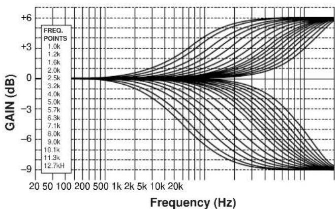
The following curves show frequency characteristics when the Parametric Equalizer (PEQ) is adjusted at the indicated values.
PEQ: FRQ 1.0 kHz GAIN +6 dB to -9 dB

line
| Frequency (Hz) | Gain (dB) | | -------------- | --------- | | 20 | 0 | | 50 | 0 | | 100 | 0 | | 200 | 0 | | 500 | 0 | | 1k | 0 | | 2k | 0 | | 5k | 0 | | 10k | 0 | | 20k | 0 | | 30k | -6 | | 40k | -9 | | 50k | -6 | | 60k | -3 | | 70k | 0 | | 80k | 3 | | 90k | 6 | | 100k | 3 | | 110k | 0 | | 120k | -3 | | 130k | -6 | | 140k | -9 | | 150k | -6 | | 160k | -3 | | 170k | 0 | | 180k | 3 | | 190k | 6 | | 200k | 3 | | 210k | 0 | | 220k | -3 | | 230k | -6 | | 240k | -9 | | 250k | -6 | | 260k | -3 | | 270k | 0 | | 280k | 3 | | 290k | 6 | | 300k | 3 | | 310k | 0 | | 320k | -3 | | 330k | -6 | | 340k | -9 | | 350k | -6 | | 360k | -3 | | 370k | 0 | | 380k | 3 | | 390k | 6 | | 400k | 3 | | 410k | 0 | | 420k | -3 | | 430k | -6 | | 440k | -9 | | 450k | -6 | | 460k | -3 | | 470k | 0 | | 480k | 3 | | 490k | 6 | | 500k | 3 | | 510k | 0 | | 520k | -3 | | 530k | -6 | | 540k | -9 | | 550k | -6 | | 560k | -3 | | 570k | 0 | | 580k | 3 | | 590k | 6 | | 600k | 3 | | 610k | 0 | | 620k | -3 | | 630k | -6 | | 640k | -9 | | 650k | -6 | | 660k | -3 | | 670k | 0 | | 680k | 3 | | 690k | 6 | | 700k | 3 | | 710k | 0 | | 720k | -3 | | 730k | -6 | | 740k | -9 | | 750k | -6 | | 760k | -3 | | 770k | 0 | | 780k | 3 | | 790k | 6 | | 800k | 3 | | 810k | 0 | | 820k | -3 | | 830k | -6 | | 840k | -9 | | 850k | -6 | | 860k | -3 | | 870k | 0 | | 880k | 3 | | 890k | 6 | | 900k | 3 | | 910k | 0 | | 920k | -3 | | 930k | -6 | | 940k | -9 | | 950k | -6 | | 960k | -3 | | 970k | 0 | | 980k | 3 | | 990k | 6 | | 1000k | 3 |PEQ: FRQ ..... 1.0 kHz to 12.7 kHz GAIN ..... +6 dB/-9 dB

line
| Frequency (Hz) | FREQ. POINTS | | -------------- | ------------ | | 20 | 1.0k | | 50 | 1.2k | | 100 | 1.6k | | 200 | 2.0k | | 500 | 2.5k | | 1k | 3.2k | | 2k | 4.0k | | 5k | 5.0k | | 10k | 5.7k | | 20k | 6.3k | | | 7.1k | | | 8.0k | | | 9.0k | | | 10.1k | | | 11.3k | | | 12.7k |8. PARAMETER INI (Initializing parameters on a DSP program)
You can initialize all parameter settings on a DSP program. Note that a DSP program has two or three subprograms; all parameters on both subprograms are initialized by this operation.
Initializing method
After selecting this function (title) in step 1 on page 32, press the + or - key to display the DSP program numbers (1 - 12). A program number whose parameters has been changed is marked with “*”. Press a DSP program selector key corresponding to the program number of which parameters you want to initialize. When initialized, the “*” mark will disappear.
9. MEMORY GUARD (Locking DSP parameters and other adjustments)
If you wish to prevent accidental alteration to DSP parameters or other adjustments on this unit, select "ON". In this position, they are locked and cannot be changed. The following functions on this unit can be locked by this operation.
- DSP parameters
- Other functions in the "SET MENU" mode
• ON SCREEN display key - LEVEL key
- TEST key
10. VCR 3 VIDEO (Switching the DVD/VCR 3 VIDEO OUT terminal to a second monitor out terminal.)
If you wish to connect a second monitor TV (or a projector) to this unit, select "MONTR" position. The DVD/VCR 3 VIDEO OUT terminal (and S VIDEO terminal also) is switched to a second monitor out terminal, so you can connect this terminal to the video input terminal of another monitor TV.
Notes
- Even in the “MONTR” position, the DVD/VCR 3 VIDEO IN terminal can be used as a normal video signal input terminal and the DVD/VCR 3 AUDIO SIGNAL IN/OUT terminals as normal audio input/output terminals.
- If using the DVD/VCR 3 terminals for connecting a third video cassette recorder only, be sure to select "REC OUT" position.
If the picture on the monitor is disturbed while the third video cassette recorder is functioning, "MONTR" position may be selected. If so, select "REC OUT" position.
11. INPUT MODE (Selecting the initial input mode of the sources connected to the TV/DBS and DVD/VCR 3 input terminals)
For the sources connected to the TV/DBS and DVD/VCR 3 input terminals of this unit only, you can designate the input mode that is automatically selected when the power of this unit is switched on.
AUTO: In this position, the AUTO input mode is always selected when the power of this unit is switched on.
LAST: In this position, the input mode you have selected the last time is memorized and will not be changed even if the power of this unit is switched on.
* Refer to page 41 for details about switching the input mode.
Operating method
After selecting this function (title) in step 1 on page 32, press the + or - key. Next select the input source TV/DBS or DVD/VCR 3 by pressing the or key so that the arrow points to its name, and then select the AUTO or LAST mode by pressing the + or - key.
12. DIMMER (Changing brightness of the display panel)
You can adjust brightness of the display panel in five degrees.
BASIC OPERATIONS
TO PLAY A SOURCE
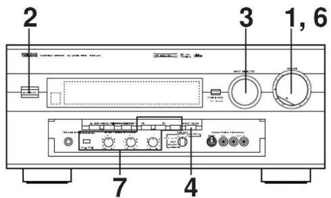
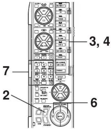
Note: If you use the remote control transmitter, be sure to use it with the lid open.
1
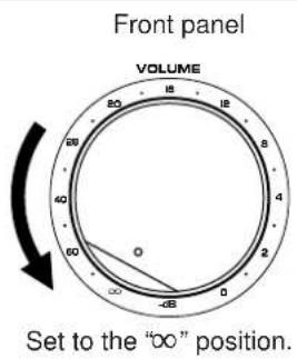
2
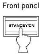
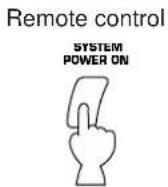
3
Select the desired input source.
(For video sources, turn the TV/monitor ON.)
The selected source is shown on the display panel and the monitor screen.
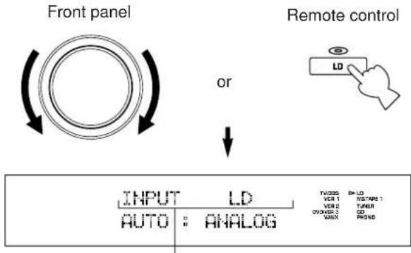
flowchart
graph TD
    A["Front panel"] --> B["OR"]
    B --> C["Remote control"]
    C --> D["INPUT LD AUTO: ANALOG"]
    D --> E["TWOSS BY LO VCR 1 VCR 2 TURER ON/OFFORD 2 CD SAUX PHSNS"]
Name of the selected input source
To select the tape deck connected to this unit's TAPE 2 terminals or the source connected to this unit's EXTERNAL DECODER INPUT terminals, refer to page 40.
For the source that inputs two or more types of signals to this unit, its current input mode is also shown.
To change the input mode, press the INPUT MODE button on the front panel or the input selector key for the currently selected source on the remote control transmitter. (Refer to page 41 for details on switching the input mode.)
4
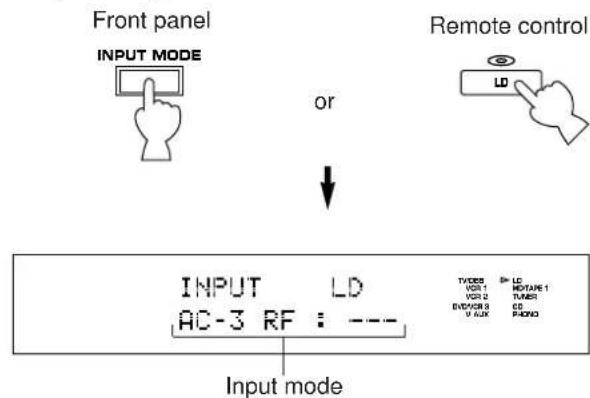
5
Play the source.
6
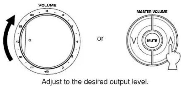
7
If desired, adjust the BASS, TREBLE, BALANCE controls, etc. (refer to page 44) and use the digital sound field processor. (Refer to pages 45 to 49.)
When you finish using this unit
Press the STANDBY/ON switch on the front panel again or the STANDBY key on the remote control transmitter to turn this unit into the standby mode.
Front panel

Remote control
or

To select the tape deck connected to this unit's TAPE 2 terminals or the source connected to this unit's EXTERNAL DECODER INPUT terminals as the input source.
Press the TAPE 2 MON/EXT. DECODER button once or more so that the corresponding indication appears on the display.
Front panel

or
Remote control
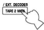

TAPE2 MONITOR ON

or
EXT. DECODER IN
"TAPE2 MONITOR ON": Lights up for a few seconds just after you select the tape deck connected to the TAPE 2 terminals.
"EXT. DECODER IN": Lights up when the source connected to the EXTERNAL DECODER INPUT terminals is selected.
Note
The input source selected in this way has priority over any other input source already selected.
To select another input source, the TAPE 2 MON/EXT.
DECODER button must be pressed so that neither the "TAPE
2 MON" indicator nor "EXT. DECODER IN" lights up on the display.
Notes on input source selection
- Note that selecting a name of input source selects the source which is connected to the corresponding input terminals on the rear panel.
* To select the source connected to the VIDEO AUX terminals on the front panel, select "VIDEO AUX".
- The setting of the TAPE 2 MON/EXT. DECODER button cannot be canceled by selecting another input source. To cancel it, press the TAPE 2 MON/EXT. DECODER button again so that neither the "TAPE 2 MON" indicator nor "EXT. DECODER IN" lights up on the display.
- If you select a video input source without canceling the setting of the TAPE 2 MON/EXT. DECODER button, the playback result will be the video image from the video source and the sound from the source selected by the TAPE 2 MON/EXT. DECODER button.
- If a different audio source is selected with the input selector keys on the remote control transmitter while enjoying a video source, the sound from the newly selected audio source is heard, but the picture from the video source can still be seen.
- When you select an input source, the DSP program (or the state of no DSP program is used) which was used when the same input source was selected the last time will be automatically recalled.
- If a nonstandardized source is played back, or the unit playing back a source is misoperating, "INPUT DATA ERROR" appears on the display.
Switching the input mode
This unit allows you to switch the input mode only for sources that input two or more types of signals to this unit.
■ For CD, MD/TAPE 1, TV/DBS and DVD/VCR 3 sources:
The following two input modes are provided.
AUTO:
This mode is automatically selected when you turn on the power of this unit. In this mode, input signal is automatically selected by the following order of priority.
- Digital signal encoded with the Dolby Digital (AC-3) or the DTS, or Normal digital input signal (PCM)
- Analog input signal (ANALOG)
* For CD, TV/DBS and DVD/VCR 3 sources, if digital signals are input from both of the OPTICAL and COAXIAL terminals, the digital signal from the OPTICAL terminal is selected.
DTS:
In this mode, only digital input signal encoded with the DTS is selected even though other signals are input at the same time.
ANALOG
In this mode, only analog input signal is selected even though digital signal is input at the same time.
Select this mode when you want to use the analog input signal instead of the digital input signal.
For LD sources:
The following five input modes are provided.
AUTO:
This mode is automatically selected when you turn on the power to this unit.
In this mode, input signal is automatically selected by the following order of priority.
- Dolby Digital (AC-3) RF signal (DOLBY DIGITAL)
- Digital signal encoded with the Dolby Digital (AC-3) or the DTS, or Normal digital input signal (PCM)
- Analog input signal (ANALOG)
AC-3 RF:
In this mode, only Dolby Digital (AC-3) RF signal is selected.
DTS:
In this mode, only digital input signal encoded with the DTS is selected even though other signals are input at the same time.
DIGITAL:
In this mode, only digital input signal is selected even though other types of signals are input at the same time.
ANALOG
In this mode, only analog input signal is selected even though other types of signals are input at the same time.
Notes on input mode selection
- For the TV/DBS and DVD/VCR 3 sources, the input mode selected on the function "11. INPUT MODE" in the SET MENU mode is selected when you turn on the power of this unit.
- To play back an LD source with the Dolby Digital (AC-3) decoded, set the input mode to "AUTO" or "AC-3 RF".
- When you want to enjoy a source which has normal 2-channel signals with a Dolby Pro Logic Surround program, select the ANALOG mode.
- In the AUTO mode, there may be a case depending on some LD players or DVD players that when you make a search on a source encoded with the Dolby Digital (AC-3) or the DTS during playback and then playback is restored, sound output is interrupted for a moment because the digital input signal is selected again.
- For sources PHONO, TUNER, TAPE 2, VCR 1, VCR 2 and V-AUX, the input mode cannot be changed because they input analog signals only to this unit.
- When the input source is changed to LD, CD, MD/TAPE 1, TV/DBS or DVD/VCR 3, or the input mode is changed, the currently selected input mode is shown on the display panel and the monitor screen.
If changed to the AUTO mode, the type of selected input signal is also shown as figured below.
INPUT CD
AUTO : PCM
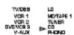
* However, if those operations are made when the test tone is output from this unit, the type of selected input signal will not be shown. (Only "AUTO" will be displayed.)
Notes on playing back a source encoded with the DTS
- When you play back an LD or CD source with the DTS decoded (with the red "dts" indicator illuminated on the display) in the AUTO mode, a noise may be heard just after playback begins. To prevent such a noise, select the DTS mode.
Be careful not to play back these sources in the ANALOG mode. If they are played back in the ANALOG mode, only a noise will be output from the speakers.
- If you play back a CD or LD source encoded with the DTS in the AUTO mode, this unit is locked in the DTS-decoding mode automatically to prevent the generation of noise possible in subsequent operations. In this state, the red "dts" indicator flashes. In this state, if you play back a CD or LD with normal (PCM) digital signals, no sound will be heard. To play back these sources normally, press the INPUT MODE button on the front panel or the input selector key for the currently selected source on the remote control transmitter so that "PCM" appears on the display.
TO RECORD A SOURCE TO TAPE (OR MD) (OR DUBBING FROM A TAPE TO ANOTHER)
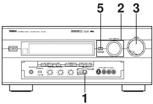
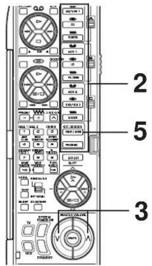
Note: If you use the remote control transmitter, be sure to use it with the lid open.
1 Set the REC OUT selector to the SOURCE position.
Front panel
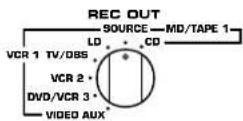
2 Select the source you want to record.
Front panel

natural_image
Simple diagram of two concentric circles with curved arrows indicating rotation or direction (no text or symbols)Remote control
or

3 Play the source and then turn the VOLUME control up to confirm the input source.
Front panel
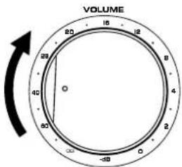
Remote control
or
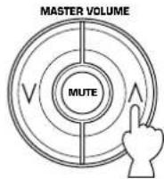
4 Begin recording on the tape deck (or MD recorder etc.) or VCR connected to this unit.
5 If the second tape deck (or MD recorder etc.) connected to this unit's TAPE 2 REC terminals is used for recording, you can monitor the sounds being recorded by pressing the TAPE 2 MON/EXT. DECODER so that the "TAPE 2 MON" indicator lights up on the display.
To record a source to tape (or MD) while listening to (or watching) another source
Regardless of the setting of the INPUT SELECTOR, when you set the REC OUT selector to CD, the audio signal from your CD player can be recorded by your first tape deck (or MD recorder) which is connected to this unit's MD/TAPE 1 REC terminals. Likewise, when the REC OUT selector is set to LD, TV/DBS, VCR 2, DVD/VCR 3 or VIDEO AUX, both the audio and video signals of the selected source can be recorded by your first VCR which is connected to this unit's VCR 1 OUT terminals.
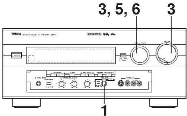
Note: If you use the remote control transmitter, be sure to use it with the lid open.

1 Select the source you want to record.
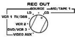
2 Play the source.
3 Confirm the source by selecting it with the INPUT
Confirm the source by selecting it with the INPUT SELECTOR and turning up the VOLUME control.
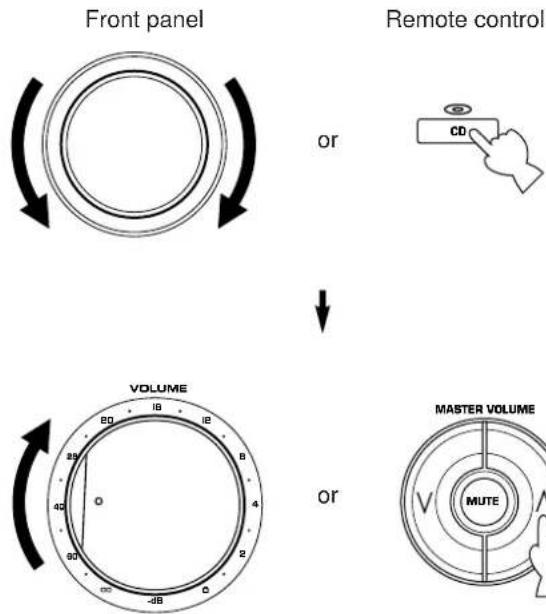
flowchart
graph TD
    A["Front panel"] -->|or| B["Remote control"]
    B --> C["VOLUME"]
    C --> D["MASTER VOLUME"]
4 Begin recording on the first tape deck (or MD recorder etc.) or the first VCR connected to this unit.
5 To monitor the sound (and picture) to be recorded (or being recorded), select the tape deck (or VCR) being used for recording with the INPUT SELECTOR.
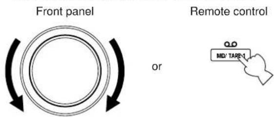
6 If you want to enjoy another source while recording, select it with the INPUT SELECTOR.
Notes
- While recording, you can use any other VCR or tape deck not selected by the REC OUT selector to record an audio and video source selected by the INPUT SELECTOR.
- The audio and video signals from VCR 2 (or DVD/VCR 3) are sent to VCR 1 when the REC OUT selector is set to VCR 2 (or DVD/VCR 3).
- If the REC OUT selector is set to VCR 2 (or DVD/VCR 3), you cannot dub from your first VCR to the second VCR (or the third VCR), even if VCR 1 is selected by the INPUT SELECTOR.
- To dub the audio signal from your second tape deck to the first one, press the TAPE 2 MON/EXT. DECODER button so that the "TAPE 2 MON" indicator lights up on the display (and set the INPUT SELECTOR to any source other than MD/TAPE 1 before beginning to record).
Notes on recording
- The settings of DSP and the VOLUME, BASS, TREBLE, BALANCE controls and the BASS EXTENSION switch have no effect on the material being recorded.
- Composite video and S video signals pass independently through this unit's video circuits. Therefore, when recording or dubbing video signals, if your video source unit is connected to provide only a S video (or only a composite video) signal, you can record only a S video (or only a composite video) signal on your VCR.
-
A source that is connected to this unit between optical digital terminals only cannot be recorded by a tape deck or VCR other than the tape deck (or MD recorder etc.) connected to the OPTICAL MD/TAPE 1 REC terminal of this unit.
-
Dolby Digital (AC-3) RF audio input signal cannot be recorded by a tape deck or VCR. To record an LD source, the LD player must be connected to the OPTICAL digital audio signal input terminal and/or analog audio signal input terminals of this unit.
- A source of signals input to the EXTERNAL DECODER INPUT terminals of this unit cannot be recorded.
- Please check the copyright laws in your country to record from records, compact discs, radio, etc. Recording of copyright material may infringe copyright laws.
If you watch a video software that uses scramble or encoded signals to prevent it from being dubbed, there may be a case that display information superimposed on the picture and/or the picture itself is disturbed due to those signals.
FOR SOUND CONTROL ON THIS UNIT
Adjusting the BALANCE control
Adjust the balance of the output volume to the left and right speakers to compensate for sound imbalance caused by speaker location or listening room conditions.
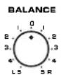
Note
This control is effective only for the sound from the main speakers.
Using the BASS EXTENSION switch
You can boost bass frequency response by setting this switch to the "ON" position. This switch is effective only on the sound from the main speakers.
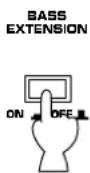
Adjusting the BASS and TREBLE controls
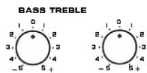
BASS : Turn this clockwise to increase (or counterclockwise to decrease) the low frequency response.
TREBLE : Turn this clockwise to increase (or counterclockwise to decrease) the high frequency response.
Note
These controls are effective only for the sound from the main speakers.
USING DIGITAL SOUND FIELD PROCESSOR (DSP)
This unit incorporates a sophisticated, multi-program digital sound field processor. The processor allows you to electronically expand and change the shape of the audio sound field from both audio and video sources, creating a theater-like experience in your listening room. You can create an excellent audio sound field by selecting a suitable sound field program (this will, of course, depend on what you will be listening to), and adding desired adjustments.
In addition, this unit incorporates a Dolby Digital (AC-3) decoder and a Dolby Pro Logic Surround decoder for multi-channel sound reproduction of sources encoded with Dolby Surround, and a DTS decoder for multi-channel sound reproduction of sources encoded with the DTS. The operation of these decoders can be controlled by selecting a corresponding DSP program including a combined operation of the YAMAHA DSP and the Dolby Digital (AC-3), the Dolby Pro Logic Surround or the DTS.
This unit has 12 programs for digital sound field processing; 6 from actual acoustic environments from around the world, and 6 programs for Audio/Video sources. In addition, each program has two or three subprograms. All programs contain various parameters that can be adjusted to the listener's taste.
For details about digital sound field programs, refer to pages 50 to 54.
PLAYING A SOURCE WITH AN EFFECT OF THE DIGITAL SOUND FIELD PROCESSOR (DSP)
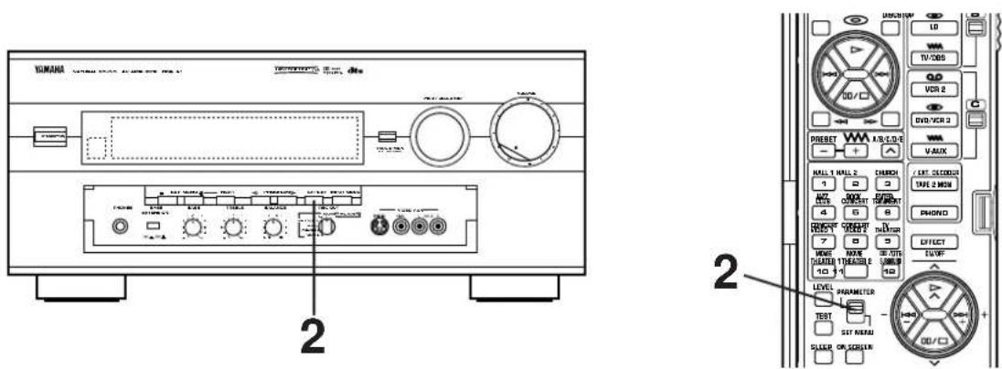
1 Follow steps 1 to 7 shown in "BASIC OPERATIONS" on page 39.
2 When operating on the front panel:
If no program name is illuminated on the display panel, press the EFFECT button to turn on the digital sound field processor so that a name of DSP program lights up on the display panel and the monitor screen.
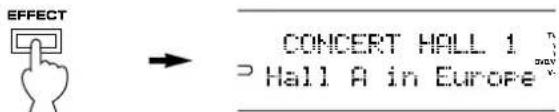
When operating on the remote control transmitter:
Set the PARAMETER/SET MENU switch to the PARAMETER position.
Note: Be sure to use the remote control transmitter with the lid open.
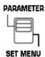
CONTINUED
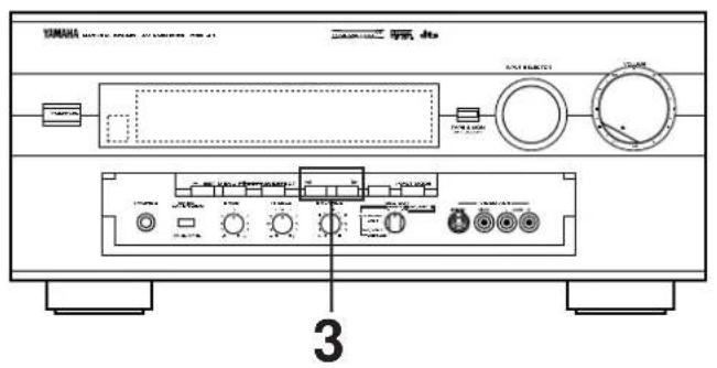
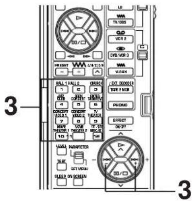
3
Select the desired program that is suitable for the source.
When operating on the front panel: When operating on the remote control transmitter:
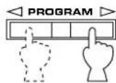
Press once or more.
a)
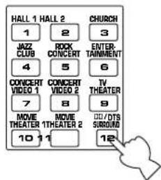
b) Select a desired subprogram by pressing the same DSP program selector key once or more, or by pressing the +/- keys.

* The name of the selected program lights up on the display panel and the monitor screen.
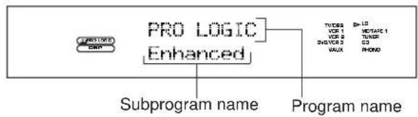
flowchart
graph TD
    A["PROLOGIC"] --> B["Subprogram name"]
    C["PRO LOGIC"] --> D["Enhanced"]
    D --> E["Program name"]
    F["VCR 1"] --> G["VCR 2"]
    H["VCR 3"] --> I["VUX"]
    J["LMATATE 1"] --> K["LMATATE 2"]
    L["TUNER"] --> M["MON"]
    N["CC"] --> O["CC"]
4
• If desired, adjust the output level of each speaker. (For details, refer to the corresponding descriptions on pages 48 and 49.)
- If desired, you can create your own sound field taste. (For details, refer to pages 56 to 60.)
Notes
- Program selection can be made to individual input sources. Once you select a program, it is linked with the input source selected at that time. So, when you select the same input source next time, the same program is automatically called.
- If you prefer to cancel the DSP, press the EFFECT button. The sound will be the normal 2-channel stereo without surround sound effect.
- When a monaural sound source is played with the program DOLBY/DTS SURROUND, no sound is heard from the main speakers and the rear speakers. Sound is heard only from the center speaker. However, if the function "1A. CENTER SP" in the SET MENU mode is set in the "NONE" position, the main speakers output the sound of the center channel.
- When this unit's Dolby Pro Logic Surround decoder, Dolby Digital decoder or DTS decoder is used, if the main-source sound is considerably altered by overadjustment of the BASS or TREBLE control, the relationship between the center and rear channels may produce an unnatural effect.
- When a source of signals input to the EXTERNAL DECODER INPUT terminals of this unit is selected, the DSP cannot be used and the EFFECT button also will not function.
To enjoy a video source encoded with the Dolby Pro Logic Surround, the Dolby Digital (AC-3) or the DTS
When you select the program No. 10, 11 or 12, and the input signal of the source is 2-channel stereo, Dolby Pro Logic Surround is decoded. When some program is selected and the input signal of the source is encoded with the Dolby Digital (AC-3), Dolby Digital (AC-3) is automatically decoded.
When some program is selected and the input signal of the source is encoded with the DTS, DTS is automatically decoded.
The following indicators on the display panel show you what sound processing is being made.
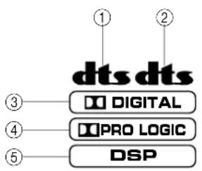
① Lights up when a DVD source encoded with the DTS is played back and the DTS is decoded.
② Lights up when an LD source or a CD source encoded with the DTS is played back and the DTS is decoded.
③ Lights up when the Dolby Digital (AC-3) is being decoded and the signals of selected source encoded with the Dolby Digital (AC-3) is not in 2-channels.
This indicator also lights up when the input mode is set to "AC-3 RF" even if no signal encoded with the Dolby Digital (AC-3) is input to this unit.
④ Lights up when the Dolby Pro Logic Surround is being decoded
⑤ Lights up when the Digital Sound Field Processor is turned on.
In addition, for the program No. 10, 11 and 12, the name of the selected subprogram on the display panel or the monitor screen will change according to the type of decoding. (For details, refer to pages 53 to 54.)
Notes
- The Dolby Digital (AC-3) will not be decoded to the source that is not encoded with the Dolby Digital (AC-3).
The DTS will not be decoded to the source that is not encoded with the DTS.
- If the input signals of source encoded with the Dolby Digital (AC-3) are in 2-channels only, the sound processing for them is similar to that for analog or PCM audio signals.
Note
If you change the LD (or CD) being played back with the DTS decoded to another disc not encoded with the DTS when the red "dts" indicator is illuminated, playing back the newly selected disc will output no sound. In this state, the red "dts" indicator flashes to show that this unit is locked in the DTS-decoding mode.
To play back the disc normally, change the current DTS-decoding mode to another mode by pressing an input selector key on the remote control transmitter or the INPUT MODE button on the front panel so that the red "dts" indicator turns off.
To cancel the effect sound
The EFFECT button on the front panel or the EFFECT ON/OFF key on the remote control transmitter make it simple to compare the normal stereo sound with the fully processed effect sound.
To cancel the effect sound and monitor only the main sound, press the EFFECT ON/OFF key or the EFFECT button. Press the EFFECT ON/OFF key or the EFFECT button a second time to restore the effect sound.
Front panel

or
Remote control

Notes
- If the effect sound is canceled when signals encoded with the Dolby Digital (AC-3) or the DTS are input to this unit, signals of all channels are mixed and are output from the main speakers.
- If the EFFECT button or the EFFECT ON/OFF key is pressed to turn effect sounds OFF when the Dolby Digital (AC-3) or the DTS is decoded, it may happen that sound is output faintly or not output normally depending on a source. In that case, press the EFFECT button or the EFFECT ON/OFF key to turn effect sounds ON, or use input signals not encoded with the Dolby Digital (AC-3) or the DTS.
- If the EFFECT button or the EFFECT ON/OFF key is pressed to turn effect sounds OFF when the Dolby Digital (AC-3) is decoded, the sampling frequency and channel formation of the decoded signal is shown on the display panel.
ex.)
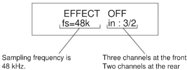
* If the input source is a Dolby Digital KARAOKE source, "K" is shown at the head of channel formation.
ADJUSTING OUTPUT LEVEL OF THE CENTER, RIGHT REAR, LEFT REAR, FRONT EFFECT SPEAKERS AND SUBWOOFER
If desired, you can adjust the sound output level of the each speaker even if the output level is already set in "SPEAKER BALANCE ADJUSTMENT" on pages 29 to 31.
Note: These adjustments can be made only when the effect sound is on. If none of the indicators ,dts DSP
DIGITAL and ATP-LOCK plated on the display panel, press the EFFECT button on the front panel or the EFFECT ON/OFF key on the remote control transmitter so that at least one of those indicators lights up on the display panel.
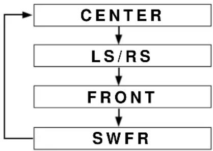
flowchart
graph TD
    A["CENTER"] --> B["LS/RS"]
    B --> C["FRONT"]
    C --> D["SWFR"]
(Center speaker output level)
(Left and right rear speaker output level)
(Front effect speaker output level)
(Subwoofer output level)
Method of adjustment
This adjustment can be made only by using the remote control transmitter.
Note: Be sure to use the remote control transmitter with the lid open.
1
Set the PARAMETER/SET MENU switch on the remote control transmitter to the PARAMETER position.

2

3
Press once or more until the name of speaker(s) whose level you want to adjust appears on the display.
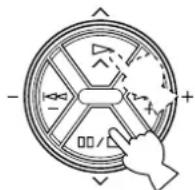
or

Whenever pressed, the selection changes as the above chart shows.
* Pressing the key on the remote control transmitter changes the selection in the reverse order.
4
Adjust the level on the selected speaker(s).
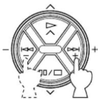
5
Repeat step 2 and 3 to make adjustments on other speaker(s).
| Speakers | Control range (dB) | Preset value |
| CENTER | MUTE, -40 to +10 | 0 |
| RIGHT SURROUND (RS) | MUTE, -40 to +10 | 0 |
| LEFT SURROUND (LS) | MUTE, -40 to +10 | 0 |
| SUBWOOFER (SWFR) | MUTE, -20 to 0 | 0 |
| FRONT | MUTE, -40 to +10 | 0 |
Notes
- In this way, the output level of left rear and right rear speakers are adjusted at the same time, keeping the difference of level between them unchanged. To adjust each level of them respectively, follow the method of "SPEAKER BALANCE ADJUSTMENT" on pages 29 to 31.
- If the function "1A. CENTER SP" in the SET MENU mode is set in the "NONE" position, the sound output level of the center speaker cannot be adjusted. This is because in this mode, the center sound is automatically output from the left and right main speakers.
- Once the output level is adjusted, the level value will be the same in all the digital sound field programs.
- The value of each speaker output level you set the last time will remain memorized even when this unit is in the standby mode. However, if the power cord is kept disconnected for more than one week, these values will be automatically changed back to the original factory settings.
BRIEF OVERVIEW OF DIGITAL SOUND FIELD PROGRAMS
The following list gives you a brief description of the sound fields produced by each of the DSP programs. Keep in mind that most of these are precise digital recreations of actual acoustic environments. The data for these sound fields were recorded at actual locations using sophisticated sound field measurement equipment.
Note
The channel level balance between the left and right rear effect speakers may vary depending on the sound field you are listening to. This is due to the fact that most of these sound field recreations are actual acoustic environments.
Program No. 1 to 6: Hi-Fi DSP programs (for audio sources)
- When the input signal is analog or PCM audio: ( ) DSP
Speaker output: main, rear, front effect
- When the input signal is encoded with the Dolby Digital (not in 2 channels): ( ) DIGITAL DSP
Speaker output: main, center, rear, front effect
- When the input signal is encoded with the DTS: (dts DSP)
Speaker output: main, center, rear, front effect
| No. | PROGRAM SUBPRO | PROGRAM (TYPE) | FEATURE |
| 1 | CONCERT Hall A in HALL 1 | Europe | This is a large fan-shaped concert hall in Munich which has approximately 2500 seats. Almost the whole interior is made of wood. There is relatively little reflection from the right and left walls, and sounds spread finely and beautifully. |
| Hall B in Europe | This is a large shoe-box type concert hall with approximately 2500 seats. Almost the whole interior except the ceiling is made of wood, including mahogany reflective panels. Special reflective paneling above the stage produces strong frontal reflections which tend to reinforce the direct sound from the stage. This hall has a very solid, powerful sound. | ||
| Hall C in Europe | A classic shoe-box type concert hall with approximately 1700 seats. Pillars and ornate carvings create extremely complex reflections. Those reflections and the reflections from all directions of the hall produce a very full, rich sound. | ||
| 2 | CONCERT Hall D in HALL 2 | U.S.A. | This is a large 2600-seat concert hall in the United States which features a fairly traditional European design. The interior is relatively simple, suggesting an American taste. Sound of the middle and high frequencies are richly and beautifully reproduced. |
| Hall E in Europe | A classic large shoe-box type concert hall with approximately 2200 seats. It has a circular stage and seats located behind the stage. | ||
| Live Concert | A large round concert hall with a rich surround effect. Pronounced reflections from all directions emphasize the extension of sounds. You will experience the sound field with a great deal of presence sitting at about the center position near the stage.This sound field is also effective for karaoke. This is because you feel as if you are standing on a real stage. | ||
| No. | PROGRAM SUBPROGRAM (TYPE) | FEATURE | |
| 3 | CHURCH Tokyo | The acoustic environment of an ordinary church with moderate reverberations. This is ideal for reproducing church music played by a pipe organ etc. | |
| Freiburg | This program recreates the acoustic environment of a big church with a high pointed dome and columns along the sides. This interior produces very long reverberations. | ||
| Royaumont | This program features a sound field created by the refectory (dining hall) of the monastery, a beautiful medieval Gothic structure located in Royaumont on the outskirts of Paris. The dome-like spaces in the ceiling formed by the supporting pillars cause reverberations to echo and create a beautiful, lingering tone. | ||
| 4 | JAZZ CLUB Village | Gate | A jazz club in New York. It is in a basement and has a relatively spacious floor area. The reflection pattern is similar to that of a small hall. |
| Village Vanguard | A traditional New York jazz club located on 7th Avenue. This room has a low ceiling, and the “stage” is located in a corner. This program does not produce nearly as many reflections as the concert hall or church programs, but creates an intimate “close-to-the-music” feel. | ||
| The Bottom Line | This is the sound field at stage front in “The Bottom Line,” a famous New York jazz club. The floor can seat 300 people to the left and right in a sound field offering real and vibrant sound. | ||
| 5 | ROCK The Roxy Theatre CONCERT | Theatre | The ideal program for lively, dynamic rock music. The data for this program was recorded at LA’s “hottest” rock club. |
| Warehouse Loft | This program simulates a space enclosed by concrete. An energetic sound field is created with relatively clear reflections by the wall. | ||
| Arena | This program gives you long delays between direct sounds and effect sounds, and extraordinarily spacious feel of a large arena theater. | ||
| 6 | ENTERTAINMENT | Disco | This program recreates the acoustic environment of a lively disco in the heart of a very lively city. The sound is dense and highly concentrated. It is also characterized by a high-energy, “immediate” sound. |
| Party | This is a sound field suitable for background music at parties where you can hear the sound directly from the rear as well, thus realizing music enjoyment over a wide area. | ||
| Game/Amusement | This program adds a deep and spatial feeling to video game sounds etc. whichever kind of source is used, stereo or monaural. You can enjoy video games with much power and presence. | ||
Program No. 7 to 12: CINEMA-DSP programs (for Audio/Video sources)
• These programs use the Dolby Pro Logic decoder, the Dolby Digital decoder or the DTS decoder.
- Speaker output for each program is as follows.
No. 7, 8, 9, 10, 11: main, center, rear, front effect
No. 12 (Normal): main, center, rear
No. 12 (Enhanced): main, center, rear, front effect
- For program No. 7, 8 and 9 only, indicators light up as follows.
When the input signal is analog or PCM audio: ( ) DSP
When the input signal is encoded with the Dolby Digital (not in 2 channels): ( ) DIGITAL DSP
When the input signal is encoded with the DTS: ( )dts DSP
| No. | PROGRAM SUBPRO | GRAM (TYPE) | FEATURE |
| 7 | CONCERT Pop/RockVIDEO 1 | This program produces an enthusiastic atmosphere and lets you feel that you are in the midst of the action, as if attending an actual jazz or rock concert.The indirect sound constituent spreads on the surround side of the sound field by the use of data of a large round hall for the surround side, so the image space around the screen and the sound space are fully expanded. | |
| DJ | With this program, the voice of a disc jockey sounds more clearly, and music entertains you with a rich sound field feeling. | ||
| 8 | CONCERT Classical VIDEO 2 | Opera | This program provides excellent depth of vocals and overall clarity, restraining excessive reverberation.For opera, the orchestra pit and the stage are ideally combined, letting you feel a full presence sound. The rear surround side of the sound field is relatively moderated, however, it reproduces beautiful sound by the use of the data of a concert hall. You will not be tired from long watching of an opera. |
| Pavilion | This program reproduces vocals clearly, letting you feel the spaciousness of a pavilion. Reverberation, which is somewhat delayed, reproduces the live sound field unique to a pavilion, and helps to make a concert scene more exciting. | ||
| 9 | TV THEATER Mono | Movie | This program is for reproducing monaural video sources (old movies etc.). Monaural sounds are reproduced with much presence by the front presence side of the sound field and optimum reverberation effect. The use of the center speaker makes conversations more audible, obtaining a pleasant mix of conversations and picture. |
| Variety/Sports | Though the front presence side of the sound field is relatively narrow, the rear surround side employs the sound environment of a large concert hall. With this program, you can enjoy watching various TV programs such as the news, variety shows, music programs or sports programs. In a stereo broadcast of a sports game, the commentator is oriented at the center position, and the shouts and the atmosphere in the stadium spread on the surround side, however, spreading of them to the rear side is properly restrained. |
- Program No. 10 to 11 are suitable for reproducing video discs, video tapes and similar sources which are encoded with the Dolby Surround (bearing the “DOLBY SURROUND” or “DOLBY DIGITAL” logo) or encoded with the DTS (bearing the “dts” logo).
| No. | PROGRAM SUBPROGRAM (TYPE) | FEATURE |
| 10 | MOVIE 70 mm SpectacleTHEATER 1( )Functions when the input signal is analog or PCM audio or encoded with the Dolby Digital (AC-3) in 2 channels.DGTL Spectacle(DIGITAL DSP)Functions when the input signal is encoded with the Dolby Digital not in 2 channels.DTS Spectacle(dts DSP)Functions when the input signal is encoded with the DTS . | This program creates the extremely wide sound field of a movie theater. It precisely reproduces the source sound in detail, giving both the video and the sound field incredible reality. Any kind of video sources encoded with the Dolby Surround or DTS (especially large-scale movie productions) are ideal for use with this program. |
| This program clearly reproduces dialog and sound effects in the latest sound design of science fiction films, thus creating a broad and expansive cinematic space amid the silence. You can enjoy science fiction films in a virtual-space sound field that includes Dolby Pro Logic, Dolby Digital (AC-3) and DTS-encoded software employing the most advanced techniques. | ||
| This program is ideal for precisely reproducing the sound design of the newest multi-track films. The sound field is made to be similar to that of the newest movie theaters, so the reverberations of the sound field itself are restrained as much as possible. The data of the sound field of an opera house are used for the front presence side, so the three dimensional feeling of the sound field is emphasized, and dialog is precisely oriented on the screen. By using the data of the sound field of a concert hall on the rear surround side, powerful reverberations are generated. You can enjoy watching action, adventure movies, etc. with much presence. | ||
| 11 | MOVIE 70 mm AdventureTHEATER 2( )Functions when the input signal is analog or PCM audio or encoded with the Dolby Digital (AC-3) in 2 channels.DGTL Adventure(DIGITAL DSP)Functions when the input signal is encoded with the Dolby Digital not in 2 channels.DTS Adventure(dts DSP)Functions when the input signal is encoded with the DTS. | This program is for reproducing sounds on a multi-track film, and characterized by a soft and extensive sound field. The front presence side of the sound field is relatively narrow. It spatially spreads all around and toward the screen, restraining echo effect of conversations without losing clarity. For the surround side, the harmony of music or chorus sounds beautifully in a wide space at the rear of the sound field. |
| This program is for reproducing sounds on a multi-track film, and characterized by a soft and extensive sound field. The front presence side of the sound field is relatively narrow. It spatially spreads all around and toward the screen, restraining echo effect of conversations without losing clarity. For the surround side, the harmony of music or chorus sounds beautifully in a wide space at the rear of the sound field. | ||
| This program is for reproducing sounds on a multi-track film, the front presence side of the sound field is relatively narrow. It spatially spreads all around and toward the screen, restraining echo effect of conversations without losing clarity. For the surround side, the harmony of music or chorus sounds beautifully in a wide space at the rear of the sound field. |
- Program No. 12 is for reproducing video discs, video tapes and similar sources which are encoded with the Dolby Surround (bearing the “DOLBY SURROUND” or “DOLBY DIGITAL” logo) or encoded with the DTS (bearing the “dts” logo).
| No. | PROGRAM SUBPROLOGRAM (TYPE) | FEATURE |
| 12 | DTS PRO LOGIC/Normal ( ) [IMAGE]SURROUND Functions when the input signal is analog or PCM audio or encoded with the Dolby Digital (AC-3) in 2 channels.DOLBY DIGITAL/Normal ( [IMAGE])Functions when the input signal is encoded with the Dolby Digital not in 2 channels.DTS DIGITAL SUR./Normal ( [dts ] )Functions when the input signal is encoded with the DTS. | The built-in Dolby Pro Logic Surround decoder, the Dolby Digital (AC-3) decoder or the DTS decoder precisely reproduces sounds and sound effects of a source encoded with the Dolby Surround or the DTS. The realization of a highly efficient decoding process improves crosstalk and channel separation and makes sound positioning smoother and more precise. |
| PRO LOGIC/Enhanced( [IMAGE] )Functions when the input signal is analog or PCM audio or encoded with the Dolby Digital (AC-3) in 2 channels.DOLBY DIGITAL/Enhanced( [IMAGE] )Functions when the input signal is encoded with the Dolby Digital not in 2 channels.DTS DIGITAL SUR./Enhanced( [dts ] )Functions when the input signal is encoded with the DTS. | This program ideally simulates the multi-surround speaker systems of the newest film theater. The digital sound field processing and the Dolby Surround decoding or the DTS decoding are precisely performed without altering the originally designed sound orientation. The surround effects produced by this sound field fold the viewer naturally from the rear to the left and right and toward the screen. |
Note: If the "NONE" position is selected on "1A. CENTER SP" in the SET MENU mode, no sound is output from the center speaker(s).
ON SCREEN DISPLAY
If you connect your video cassette recorder, LD player, video monitor, etc. to this unit, you can take advantage of this unit's capability to display program titles, parameter data and information for various setting changes and adjustments on your video monitor's screen. This information will be superimposed over the video image.
If there is no video source connected or it is turned off, the information will be displayed over a blue colored background.
P01 CONCERT HALL 1
→ Hall A in Europe EFCT TRIM ···· Q dB INIT. DLY ···· 30ms ROOM SIZE ···· 1/0 LIVENESS ····· · 5
Note: The program titles, parameter data and other information are also displayed on the display panel of this unit.
Selecting a type of display
You can change the type of display showing various information on the monitor's screen by pressing the ON SCREEN display key on the remote control transmitter. Whenever pressed, the screen changes to a full display, a simple display and no display in turn.

(Example)
Full display
P01 CONCERT HALL 1
→ Hall A in Europe EFCT TRIM ····0 d B INIT. DLY ····30ms ROOM SIZE ····1/0 LIVENESS ······5
Simple display
P01 CONCERT HALL 1 Hall A in Europe
Goes off after being displayed for several seconds.
Notes
- When making a setting change or adjustment in the SET MENU mode, or making speaker balance adjustment by using the test tone, information is fully displayed on the monitor's screen even if another type of display is currently selected.
- Information displayed on the monitor's screen in this way cannot be recorded by a VCR.
CREATING YOUR OWN SOUND FIELDS
WHAT IS A SOUND FIELD?
In order to explain the impressive functions of the DSP, we need to first understand what a sound field really is.
What really creates the rich, full tones of a live instrument are the multiple reflections from the walls of the room. In addition to making the sound "live", these reflections enable us to tell where the player is situated, and the size and shape of the room in which we are sitting. We can even tell whether it is highly reflective with steel and glass surfaces, or more absorbent with wood panels, carpeting and curtains.
THE ELEMENTS OF A SOUND FIELD
In any environment, in addition to the direct sound coming straight to our ears from the player's instrument, there are two distinct types of sound reflections that combine to make up the sound field:
(1) Early Reflections.
Reflected sounds reach our ears extremely rapidly (50 ms — 100 ms after the direct sound), after reflecting from one surface only—for example, from the ceiling or a wall. These reflections fall into specific patterns as shown in the diagram on page 58 for any particular environment, and provide vital information to our ears. Early reflections actually add clarity to the direct sound.
(2) Reverberations.
These are caused by reflections from more than one surface—walls, ceiling, the back of the room—so numerous that they merge together to form a continuous sonic “afterglow”. They are non-directional, and lessen the clarity of the direct sound.
Direct sound, early reflections and subsequent reverberation taken together help us to determine the subjective size and shape of the room, and it is this information that the DSP reproduces in order to create sound fields.
If you could create the appropriate early reflections and subsequent reverberations in your listening room, you would be able to create your own listening environment. The acoustics in your room could be changed to those of a concert hall, a dance floor, or virtually any size room at all. This ability to create sound fields at will is exactly what Yamaha has done with the DSP.
DSP programs consist of some parameters to determine apparent room size, reverberation time, distance from you to the performer, etc. In each program, these parameters are preset with values precisely calculated by Yamaha to create the sound field unique for the program. It is recommended to use DSP programs without changing values of parameters, however, this unit also allows you to create your own sound fields. Starting with one of the built-in programs, you can adjust those parameters. Even if this unit is in the standby mode, your custom sound fields will remain in the DSP's memory for about two weeks. The following page details how to make your own sound fields.
In addition to the “TYPE” parameter which selects the subprograms within each DSP program (e.g. “Hall A in Europe”, “Hall B in Europe” and “Hall C in Europe” for program 1, “HALL 1”), each program also has a set of parameters that allow you to change the characteristics of the acoustic environment to create precisely the effect you want. These parameters correspond to the many natural acoustic factors that create the sound field you experience in an actual concert hall or other listening environment. The size of the room, for example, affects the length of time between the “early reflections”—that is, the first few widely spaced reflections you hear after the direct sound. The “ROOM SIZE” parameter provided in many of the DSP programs alters the timing between these reflections, thus changing the shape of the “room” you hear. In addition to room size, the shape of the room and the characteristics of its surfaces have a significant effect on the final sound. Surfaces that absorb sound, for example, cause the reflections and reverberations to die out quicker, while highly reflective surfaces allow the reflections to carry on for a longer period of time. The DSP parameters allow you to control these and many other factors that contribute to your personal sound field, allowing you to essentially “redesign” the concert halls and rooms provided to create custom-tailored listening environments that ideally match your mood and music.
Refer to "DESCRIPTIONS OF THE DIGITAL SOUND FIELD PARAMETERS" on pages 58 to 60 for a description of what each parameter does, how it effects the sound, and its control range.
SELECTING AND EDITING PROGRAM PARAMETERS
This adjustment can be made only by using the remote control transmitter watching the monitor screen or the display panel.
Note
It is recommended to watch the monitor screen for making adjustments more easily than to watch the display panel.
1 Set the PARAMETER/SET MENU switch to the PARAMETER position.
Note: Be sure to use the remote control transmitter with the lid open.
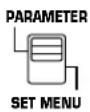
2 Turn your monitor on. If the currently selected type of display is not the full display, press the ON SCREEN display key to call the full display.

3 If no DSP program is selected, select a desired program.
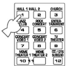
The selected program name and its parameters will be displayed on the monitor screen. The arrow-shaped cursor points to the subprogram name.
P01 CONCERT HALL 1
Press the button for the currently selected program once or more.
5 Select the parameter which you want to edit.
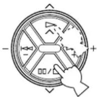
6 Change the value on the selected parameter to create the effect you want.
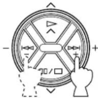
“+” increases the value of the selected parameter, and “−” decreases the value of the selected parameter. In both cases you can hold the key down for continuous incrementing or decrementing.
The display will pause for a moment at the initial value of the parameter as a reminder. (On the monitor screen, mark at the head of parameter name disappears at the initial value of the parameter.)
Notes
• For details about parameters, refer to pages 58 to 60.
- Parameter edits made in this way will remain in effect even with power cut due to power failure or the power plug disconnected from the AC outlet for up to about two weeks, after which all parameters, as well as other adjustments or setting changes on this unit, will return to their initial values or conditions.
DESCRIPTIONS OF THE DIGITAL SOUND FIELD PARAMETERS
Not all of the following parameters are found in every program.
- ROOM SIZE
How it Affects the Sound:
Changes the apparent size of the music venue. The larger the value, the larger the simulated room will sound.
What it Does:
Adjusts the timing between the early reflections. Early reflections are the first group of reflections you hear before the subsequent, dense reverberation begins.
Control Range:
0.1 - 2.0
Standard setting is 1.0.
Changing this parameter from 1 to 2 increases the apparent volume of the room eight times (length, width, and height all doubled).
P. ROOM SIZE (Presence Room Size)
Adjusts the apparent space size of the front presence sound field. The larger the value, the longer the interval between reflections becomes, which increases the depth of the sound source.
S. ROOM SIZE (Surround Room Size)
Adjusts the apparent space size of the rear surround sound field. The larger the value, the larger the surround sound field becomes.
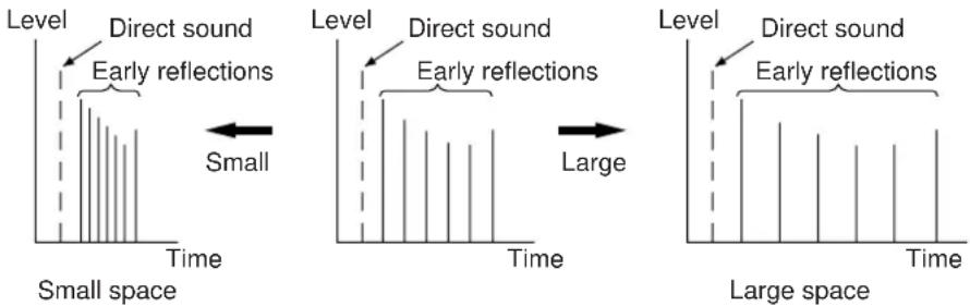
• INIT. DLY (Initial Delay)
How it Affects the Sound:
Changes the apparent distance from the source sound.
Since the distance between a sound source and a reflective surface determines the delay between the direct sound and the first reflection, this parameter changes the location of the sound source within the acoustic environment.
What it Does:
Adjusts the delay between the direct sound and the first reflection heard by the listener.
Control Range:
1 – 99 milliseconds
For a small living room this parameter would be set for a small value. Large values for a big room. Larger values produce an echo effect.
P. INIT. DLY (Presence Initial Delay)
Adjusts the delay between the direct sound and the first reflection on the presence side of the sound field. The larger the value, the later the first reflection begins.
Control Range:
1 – 99 milliseconds
S. INIT. DLY (Surround Initial Delay)
Adjusts the delay between the direct sound and the first reflection on the rear surround side of the sound field. The larger the value, the later the first reflection begins.
Control Range:
1 – 49 milliseconds
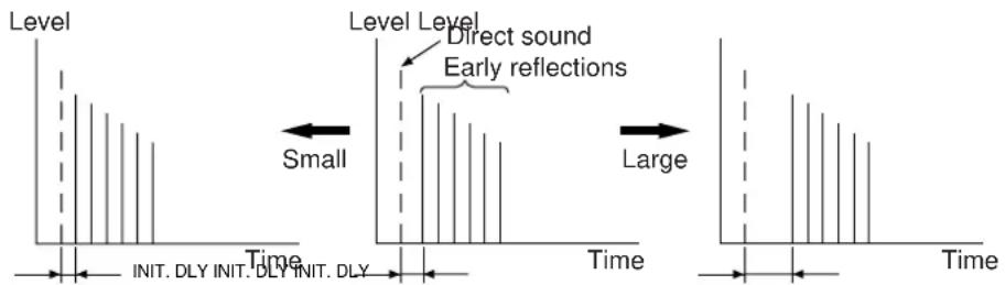
- LIVENESS
How it Affects the Sound:
This parameter changes the apparent reflectivity of the walls in the hall.
The early reflections from a sound source will lose intensity (decay) much faster in a room with acoustically absorbent wall surfaces than in one which has mostly reflective surfaces. A room with highly reflective surfaces in which the early reflections decay slowly is termed "live", while a room with absorbent characteristics in which the reflections decay rapidly is termed "dead". The LIVENESS parameter lets you adjust the early reflection decay rate, and thus the "liveness" of the room.
What it Does:
Changes the rate at which the early reflections decay.
Control Range:
0 - 10.
P. LIVENESS (Presence Liveness)
Adjusts the apparent reflectivity of the walls on the front presence sound field. The larger the value, the more reflective the front presence sound field becomes.
S. LIVENESS (Surround Liveness)
Adjusts the apparent reflectivity of the walls on the rear surround sound field. The larger the value, the more reflective the rear surround sound field becomes.
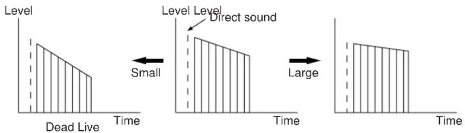
• REV. TIME (Reverberation Time)
How it Affects the Sound:
The natural reverberation time of a room depends primarily on its size and the characteristics of its inner surfaces. This parameter, therefore, changes the apparent size of the acoustic environment over an extremely wide range.
What it Does:
Adjusts the amount of time it takes for the level of the dense, subsequent reverberation sound to decay by 60 dB (1 kHz).
Control Range:
1.0 - 5.0 seconds.
The reverb time in a small-to-medium size hall would be between 1 and 2, and in a large hall it is normally between 2 and 3.
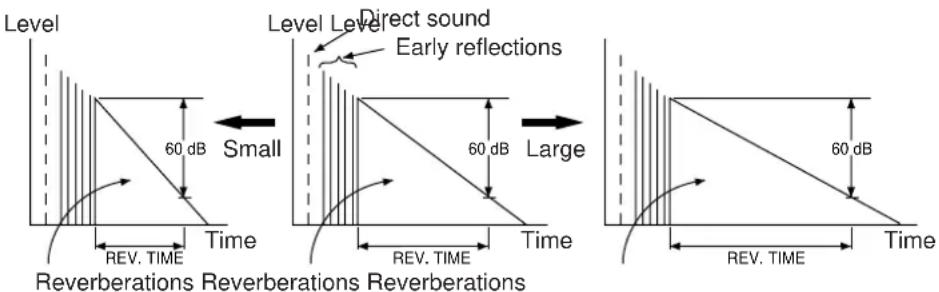
• REV. DELAY (Reverberation Delay)
This parameter sets the time difference between the beginning of the direct sound and the beginning of the reverberation sound. The larger the value, the later the reverberation sound will begin. A later reverberation sound makes you feel like the space of the acoustic environment has become larger.
Control Range:
0 – 250 milliseconds
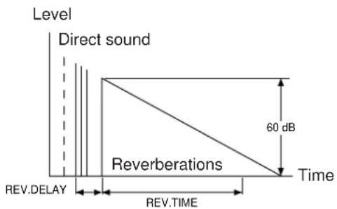
• REV. LEVEL (Reverberation Level)
This parameter adjusts the volume of the reverberation sound. The larger the value, the stronger the reverberation becomes.
Control Range:
0 - 100%
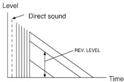
• EFCT TRIM (Effect Trim)
Performs fine adjustment of the level of all the effect sounds.
Control Range:
-3 dB to 3 dB
• S. DELAY (Surround Delay)
Adjusts the delay between the direct sound and the first reflection on the rear surround side sound field. The larger the value, the later the surround sound field is generated.
Control Range:
When the Dolby Pro Logic Surround is decoded:
15 – 30 milliseconds
When the Dolby Digital (AC-3) or the DTS is decoded:
0 – 15 milliseconds
When a program without the Dolby Surround or the DTS encoded is used:
0 – 15 milliseconds
SETTING THE SLEEP TIMER
If you use the SLEEP timer of this unit, you can make this unit turn into the standby mode. When you are going to sleep while enjoying a broadcast or other desired input source, this timer function is helpful.
Notes
- The SLEEP timer can be controlled only with the remote control transmitter.
- The components on which the SLEEP timer is effective are the sources connected to the SWITCHED AC OUTLET(S) on the rear panel of this unit.
To set the SLEEP time
1

Press once or more to select the desired SLEEP time.

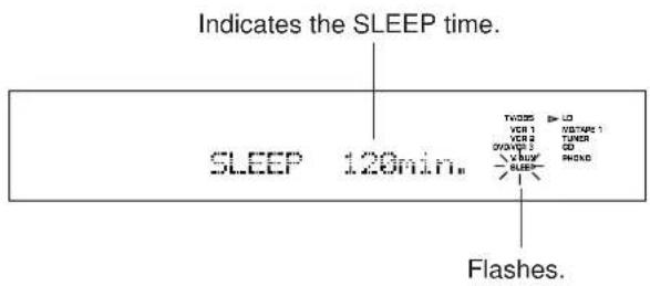
Whenever the SLEEP key is pressed, the SLEEP time will change as follows.
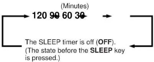
flowchart
graph LR
    A["120 99 60 30"] --> B["The SLEEP timer is off (OFF). (The state before the SLEEP key is pressed.)"]
    B --> C["End"]
After a while, the display returns to the indication before the SLEEP timer is set.
The unit will be turned into the standby mode automatically at the selected SLEEP time.
2
To cancel the selected SLEEP time
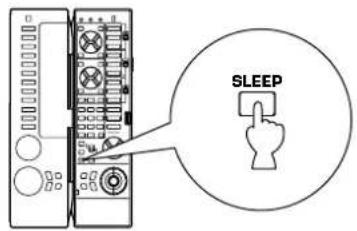
Press once or more so that "SLEEP OFF" appears on the display. (It will soon disappear and the "SLEEP" indicator will go off from the display.)
Note
The SLEEP timer setting can also be canceled by turning this unit into the standby mode with the STANDBY/ON switch on the front panel (or the STANDBY key on the remote control transmitter) or disconnecting the power plug of this unit from the AC outlet.
BASIC OPERATIONS (When the lid is open)
The remote control transmitter provided with this unit is designed to control all the most commonly used functions of this unit. If the CD player, tape deck, tuner, LD player, etc. connected to this unit are YAMAHA components designed for remote control compatibility, then this remote control transmitter will also control various functions of each component.
* For basic operations, use the remote control transmitter with the lid open.
NAMES OF KEYS AND THEIR FUNCTIONS
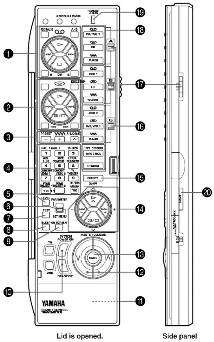
1 Tape deck keys
Control tape deck.
(The A/B/C switch (17) should be set to the "A" position.)
* DIR A, B and A/B are applicable only to double cassette tape deck.
* For a single cassette deck with automatic reverse function, pressing DIR A will reverse the direction of tape running.
2 CD/LD player keys
Control compact disc player or LD player.
(To control compact disc player, set the A/B/C switch (17) to the "A" position. To control LD player, set the A/B/C switch
(17) to the "B" position.)
* DISC is applicable only to compact disc changer.
* STOP is applicable only to LD player.
3 Tuner keys
Control tuner.
(The A/B/C switch (17) should be set to the "A" position.)
+: Selects higher preset station number.
-: Selects lower preset station number.
A/B/C/D/E: Selects the group (A - E) of preset station numbers.
4 DSP program selector keys
Select a DSP program when the built-in digital sound field processor (including the Dolby Pro Logic Surround decoder, the Dolby Digital (AC-3) decoder and the DTS decoder) is on.
5 LEVEL key
When you will adjust output level of the center speaker(s), rear speakers, front effect speakers or subwoofer, first press this key once or more so that the name of speaker(s) whose level you want to adjust appears on the display. While the name is illuminated on the display, you can change the level by pressing the + or - keys (14)
6 PARAMETER/SET MENU switch
Set to the PARAMETER position when you edit a parameter of a DSP program. Set to the SET MENU position when you will make an adjustment or setting change on a function in the SET MENU mode.
7 TEST key
Used for speaker balance adjustment. (For details, refer to pages 29 to 31.)
8 SLEEP timer key
This key is used to turn the built-in SLEEP timer on and off, and to set the SLEEP time. (For details, refer to page 61.)
9 ON SCREEN display key
Changes the type of display showing the program name and parameters, or information for various setting changes and adjustments on the connected monitor's screen.
Whenever pressed, the screen changes to a full display, a simple display and no display in turn.
10 SYSTEM POWER ON and STANDBY keys
Pressing the SYSTEM POWER ON key turns the power to this unit on and pressing the STANDBY key turns this unit into the standby mode.
11 RESET button
This button is inside the battery compartment. Press this button to "reset" the internal microcomputer which controls remote control operations. Microcomputer "reset" is necessary when the remote control freezes.
* Pressing the RESET button will not erase learned functions.
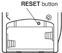
12 MASTER VOLUME (up) and (down) keys
Turn the volume level up and down.
13 MUTE key
When pressed, this key mutes the volume level. To resume the original volume level, press this key again.
While muting, the indicator on the VOLUME control flashes continuously.
14 ^/ and -/+ keys
(up) and (down) keys change parameters (or functions) in the mode selected by the PARAMETER/SET MENU switch. - and + keys make an adjustment or setting change on the parameter (or function) selected by the or key.
15 EFFECT ON/OFF key
Switches on/off the digital sound field processor (including the Dolby Pro Logic Surround decoder, the Dolby Digital (AC-3) decoder and the DTS decoder).
16 A/B/C indicators
The position (A, B or C) selected by the A/B/C switch is shown in red.
17 A/B/C switch
This switch must be used only when the lid of the remote control transmitter is open. (This switch will not function when the lid is closed.)
Normally, set this switch to the "A" position. When controlling a Yamaha LD player by using the CD/LD player keys (②), set this switch to the "B" position.
18 Input selector keys
Select input source. The TAPE 2 MON key differs from other input selector keys in function. It is identical with the TAPE 2 MON/EXT. DECODER button on the front panel. Refer to page 23 for details.
19 TRANSMIT/LEARN indicator
Lights up when the remote control transmitter is transmitting infrared signals (when a command key is pressed).
20 LIGHT key
If this key is pressed, some of the keys on the remote control unit light up for about 5 seconds. If this key is pressed while those keys are lighting up, they stop lighting.
Note
When using the keys to control Yamaha components, identify them with your component's keys. If these keys are identical, their functions will be the same. For each key function, refer to the corresponding instruction in your component's manual.
This is a learning remote control transmitter. The shaded keys in the illustration shown below can be programmed to “learn” control functions from other remote control transmitters. By learning key-functions from other remote control transmitter, this unit can then be used in place of one or more other remote control transmitters, thus making operation of your various audio and video components more convenient.
Some of the “learning-capable” keys are originally empty and others have already been preset with functions to control this unit and other Yamaha components. You can store new functions to them (in place of preset functions) as desired.
* See page 70 for the learning method.
* See page 72 for clearing a learned function (or all learned functions).
Note
If the memory capacity of the remote control transmitter becomes full, no further learning is possible even if some learning-capable keys are not occupied with new functions. If, for example, you store Yamaha codes only into this remote control transmitter, up to about 50 functions can be stored. Store new functions to the learnable-capable keys which are useful for you.
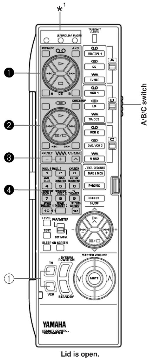
^*1 : These buttons are used for learning a new function or clearing a learned function (or all learned functions). For details, refer to pages 70 to 72.
Keys which can have three functions (1, 2, 3, 4)
In the “Learning-capable” keys, the keys numbered 1–4 in the illustration at left can have three functions. This is because they have three memory areas (A, B and C). (One function per area.) You can store new functions into the area B and C, and use three functions on a key by switching the memory areas with the A/B/C switch. (Area A cannot learn a new function.)
To use these keys:
- Before using a key, select the area A, B or C of the key on which the function you want to use is stored by using the A/B/C switch.
- Press the key.
The original factory settings of these keys are as follows.
| The position of A/B/C switch | |||
| A | B | C | |
| 1 | Preset with functions for controlling a Yamaha tape deck. | Empty | Empty |
| 2 | Preset with functions for controlling a Yamaha CD player. (STOP is empty.) | Preset with functions for controlling a Yamaha LD player. (DISC is empty.) | Empty |
| 3 | Preset with functions for controlling a Yamaha tuner. | Empty | Empty |
| 4 | Preset as the DSP program selector keys | Preset as the DSP program selector keys | Preset as the DSP program selector keys |
Note
The area A of all keys cannot learn new functions. To store new functions to these keys, store them onto the area B or C.
Empty keys (①)
These are empty keys. Each key can learn a function from another remote control transmitter.
For example, the TV key is useful for storing the function of your TV's power switch, and the VCR key can be used for your VCR's power switch.
Note
If a key which has a preset function learns a new function, the preset function will not be deleted, but disabled. When the learned function is cleared, the preset function is restored. (For information on clearing a learned function, refer to page 72.)
About the marks shown on the remote control transmitter
The marks on the remote control transmitter signify functions of keys, input sources, etc.
Examples)
∞ (tape): Tape deck, VCR, etc.
(disc): CD player, LD player, etc.
ww (radio wave): Tuner, TV/BS tuner, etc.
These marks are helpful for storing new functions.
Examples)
- The area B of keys 1 is suitable for storing functions to control your VCR.
- The area B of keys ③ is suitable for storing functions to control your TV/BS tuner.
About the lighting of keys
When you press an input selector key, it lights up for about 3 seconds.
When an input selector key in the group of selected memory area (A, B or C) is pressed, the mark of key group (1-3) which is the same as the mark of the selected input selector key lights up for about 3 seconds.
Example)
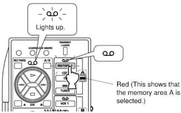
Conversely, when a key of group 1—3 is pressed, its mark and the input selector key with the same mark in the group of the selected memory area light up for about 3 seconds.
This feature may be helpful for you if you store functions for controlling an input source to a group of keys whose mark lights up when the corresponding input selector key is pressed.
When the lid of the remote control transmitter is closed, you can easily operate Yamaha components including learned functions by using the OPERATION CONTROL keys.
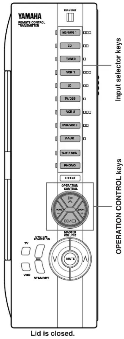
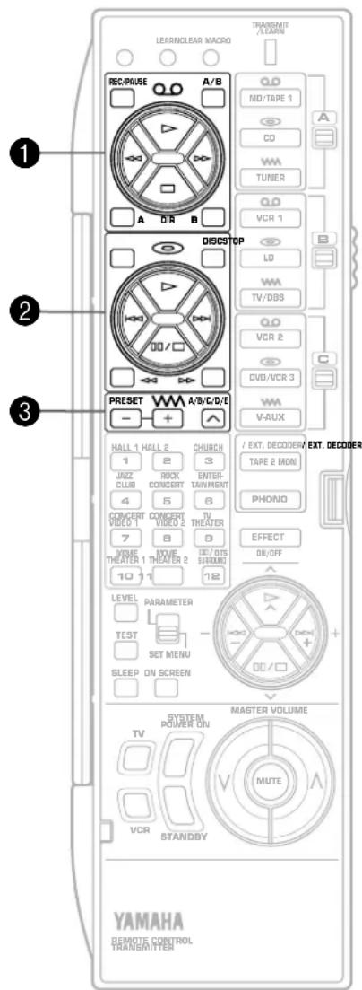
When the lid is closed, the OPERATION CONTROL keys substitute for the keys numbered ①, ② and ③ on the above illustration. To use these keys, you do not have to switch the A/B/C switch. The functions which the OPERATION CONTROL keys carry out are determined by which input selector key was pressed before using the OPERATION CONTROL keys.
Note
When the lid is closed, the EFFECT, MASTER VOLUME, MUTE, TV and VCR keys will function in the same way as when the lid is open.
* If the MACRO switch on the side of the remote control transmitter is set to "OFF", when the lid is closed, the SYSTEM POWER ON and STANDBY keys also will function in the same way as when the lid is open.
Examples of operations controlled by using the OPERATION CONTROL keys
To operate a Yamaha CD player
- Press the "CD" input selector key.
- Use the OPERATION CONTROL keys. (They carry out the functions in area A of keys ②.)
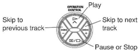
To operate your VCR
- Press the "VCR" input selector key.
- Use the OPERATION CONTROL keys. (They carry out the functions in area B of keys 1. This area is originally preset with no function. You must store the functions related to controlling the VCR in area B of keys 1 beforehand.)
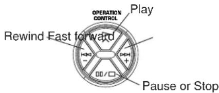
See the table below for a combination of an input selector key and key functions which the OPERATION CONTROL keys carry out. (Also, refer to the table on page 64.)
| Selected input selector | Key functions which the OPERATION CONTROL keys carry out |
| MD/ TAPE 1 | Functions in area A of keys 1 (except REC/PAUSE, A/B, DIR A and B) |
| CD | Functions in area A of keys 2 (except STOP, DISC, ◀◀ and ▷▶ ) |
| TUNER | Functions in area A of keys 3 |
| VCR 1 | Functions in area B of keys 1 (except REC/PAUSE, A/B, DIR A and B) |
| LD | Functions in area B of keys 2 (except STOP, DISC, ◀◀ and ▷▶ ) |
| TV/DBS | Functions in area B of keys 3 |
| VCR 2 | Functions in area C of keys 1 (except REC/PAUSE, A/B, DIR A and B) |
| DVD/ VCR 3 | Functions in area C of keys 2 (except STOP, DISC, ◀◀ and ▷▶ ) |
| VAUX | Functions in area C of keys 3 |
Pressing the "TAPE 2 MON" or "PHONO" input selector key has no effect on the OPERATION CONTROL keys.
Notes
- If the OPERATION CONTROL keys substitute for keys which have no function (empty), no command is carried out. According to your plan, store functions from other remote control transmitters into an empty area of those keys. (Refer to page 70 for the learning method.)
- While playing an audio/video unit, if you want to operate another unit by using the remote control transmitter (for example, if you want to rewind a tape on your VCR while listening to a CD), you should open the lid of the remote control transmitter and use the A/B/C switch and the corresponding keys.
(If you press an input selector key with the lid closed to change the functions of the OPERATION CONTROL keys to the functions for controlling a VCR, the input of currently playing CD source is canceled.)
About the lighting of keys
When an input selector key is pressed, the pressed key and only the available OPERATION CONTROL keys (which substitute for the keys stored with the preset functions or learned functions) light up for about 3 seconds. So you will know what keys are available at a glance.
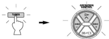
Conversely, when an OPERATION CONTROL key is pressed, all of the available OPERATION CONTROL keys and the currently selected input selector key light up.
"Macro" is a command which defines a sequence of several operations.
The keys shown in the illustrations below (as preset macro keys) are also preset with macros, in addition to individual functions.
Each macro key is preset so that simply pressing it alone will carry out several functions of other keys on this remote control transmitter sequentially. (To know what key functions are sequentially carried out by pressing each preset macro key, see the next page.)
Macros can be used only when the lid is closed and the MACRO switch is set to "SLOW" or "QUICK". (If "OFF" is selected, no macro will function even if the lid is closed.)
Preset macro keys are originally preset with macros. If you prefer, however, you can change the contents of a macro key by storing a desired series of functions on it. You can store up to seven functions onto a macro key. (Refer to page 71 for the learning method.)
Setting the MACRO switch
OFF: In this position, no macro will function even if the lid of remote control transmitter is closed.
QUICK: In this position, when a macro key is pressed, each command is transmitted at 0.5 second intervals.
SLOW: In this position, when a macro key is pressed, each command is transmitted at 3 second intervals.
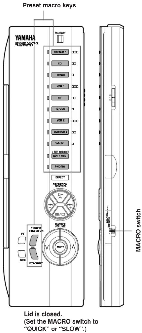
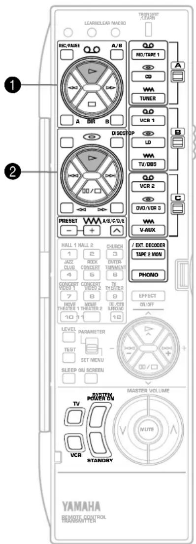
Preset macro keys and the key functions which they carry out sequentially are as follows. (Also, refer to the table on page 64.)
| Macro key | Function of the key (and area) which operates when a macro key is pressed | ||
| 1st(Turning the power of this unit on) | 2nd(Selecting an input source) | 3rd(Playing a source) | |
 | MD/ TAPE 1 | “▷” on area A of keys 1 | |
| CD | “▷” on area A of keys 2 | ||
| TUNER | - | ||
| VCR 1 | “▷” on area B of keys 1 | ||
| LD | “▷” on area B of keys 2 | ||
| TV/DBS | - | ||
| VCR 2 | “▷” on area C of keys 1 | ||
| DVD/ VCR 3 | “▷” on area C of keys 2 | ||
| V-AUX | - | ||
| TAPE 2 MON | - | ||
| PHONO | - | ||
| Macro key | Function of the key which operates when a macro key is pressed | ||
| 1st 2nd | 3rd | ||
 |  | TV | VCR |
 |  | ||
 |  | - | - |
| STANDBY | STANDBY | ||
Notes
- A key in which no function is stored will carry out no command.
- If it occurs that this unit will not receive the second command because the internal operation of the first command takes a long time, set the MACRO switch to the "SLOW" position, or add no function or repeat the same command between the first command and the next command.
-
If you program the power on/off switching function of TV, VCR, etc. as part of a macro sequence, note that it switches the current mode to the other ("on" to "off", or "off" to "on"). For example, when you press the macro key, if the power of TV, VCR, etc. is already on, the power will be turned off even though you may not want it to do so.
-
Once you press a macro key, this unit will not receive the command of another key (even if it is pressed) until this unit finishes carrying out all commands of the macro key. Take notice of this especially when the MACRO switch is in the "SLOW" position.
- Once you press a macro key, you must keep the remote control transmitter directed at the main unit's remote control sensor until the remote control transmitter finishes transmitting all command signals of the macro key.
- You can also use the OPERATION CONTROL keys while using the macro functions.
1 Place this remote control transmitter and the other remote control transmitter so that they face each other.
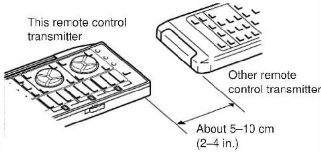
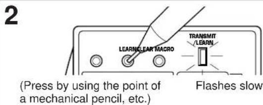
* If there is no operation for about 30 seconds after the LEARN button is pressed, the TRANSMIT/LEARN indicator flashes rapidly and the current mode is canceled. If this occurs, repeat this step.
3 If necessary, select the memory area by using the A/B/C switch on the side panel of the remote control transmitter.

4 Press the key on this remote control transmitter in which you will store a new function.
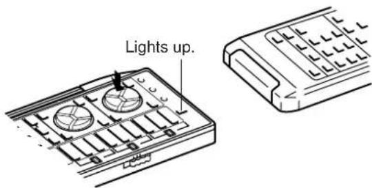
* If a key which cannot learn another function is pressed, the TRANSMIT/LEARN indicator flashes rapidly and the current mode is canceled. If this occurs, repeat this step. * If there is no operation for about 30 seconds after a key is pressed, the TRANSMIT/LEARN indicator flashes rapidly and the mode before you began learning operations is restored. If this occurs, restart from step 2.
5 Press and hold the key (on the other remote control transmitter) which has the function you want to store.
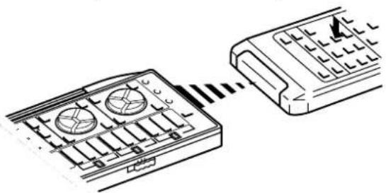
natural_image
Diagram showing a device with two circular components connected to a control panel (no text or symbols present)When learning is finished, the TRANSMIT/LEARN indicator stops lighting. You can release the key. Then the indicator begins flashing slowly.
* If a signal is not successfully received, the TRANSMIT/LEARN indicator flashes rapidly and the mode prior to step 4 is restored. If this occurs, restart from step 4. * If memory capacity is full, the TRANSMIT/LEARN indicator flashes rapidly to show you that learning is impossible, and then the mode before you began learning operations is restored.
6 Repeat step 3–5 to store more functions.
7 When you finish the learning operation, press the LEARN button.
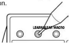
Notes
- Newly learned functions will replace previously learned functions.
- If there is no more room in the memory area for a function to be learned, the TRANSMIT/LEARN indicator will flash rapidly. In this case, even if some keys are not occupied with functions from other remote control transmitters, no further learning is possible.
- If you close the lid while learning, and then about 5 seconds pass, the TRANSMIT/LEARN indicator flashes rapidly and the mode before beginning learning operations is restored. If this occurs, restart from step 2. However, if you open the lid within 5 seconds, the mode before closing the lid is restored.
- There may occasionally be instances in which, due to the signal-coding and modulation employed by the other remote control transmitter, this remote control transmitter will not be able to "learn" its signals.
- When you press the LEARN, MACRO or CLEAR button, or the RESET button inside of the battery compartment by using a sharp-pointed thing, be careful not to damage the button. If you will use a mechanical pencil, make sure that the lead is not coming out.
A new macro can be programmed onto any preset macro key in place of preset functions. (See page 68 to know what keys are preset macro keys.) You can make as many as 13 new macro keys. A macro key can learn as many as seven functions of other keys.
Note
If you store a continuous command such as lowering of volume level, it will become a short command when it is carried out as a part of macro.
1
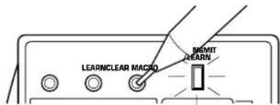
Flashes slowly.
* If there is no operation for about 30 seconds after the MACRO button is pressed, the TRANSMIT/LEARN indicator flashes rapidly and the mode before you pressed the MACRO button is restored. If this occurs, press the MACRO button again.
2
Press a preset macro key on which you want to make a new macro.
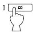

Lights up.
* If a key other than a preset macro key is pressed, the TRANSMIT/LEARN indicator flashes rapidly and the current mode is canceled. If this occurs, repeat this step.
3
Press a key whose function you want to store as the first function of the new macro.


Goes off.
(When learning is finished, this indicator lights up again.)
* If a key whose function cannot be stored as a command of macro is pressed, the TRANSMIT/LEARN indicator flashes rapidly and the current mode is canceled. If this occurs, repeat this step.
* If about 30 seconds pass before a key is pressed, the TRANSMIT/LEARN indicator flashes rapidly and the mode before you began learning operations is restored. If this occurs, restart from step 1.
4
Repeat step 3 to store the second, the third and more functions. You can store up to seven key functions in series as a macro.
* If the seventh key function has been learned, the TRANSMIT/LEARN indicator flashes rapidly and the mode before you began learning operations is restored. (This shows that the key has completed learning a series of functions as a macro.) If this occurs, you do not have to follow the next step.
5
When you finish learning, press the MACRO button.
It is recommended to write down new key functions you stored on the provided user function stickers and paste them on the reverse side of the remote control transmitter or the reverse side of the remote control transmitter's lid.
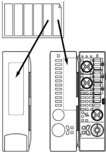
natural_image
Diagram showing front and back views of a computer tower with labeled ports and connectors (no text or symbols present)Memory back-up
All of the learned functions will be retained while you replace the batteries. However, if no batteries are installed for a few hours, the learned functions will be erased and will have to be learned again.
To Clear a Learned Function To Clear All Learned Functions
1 To clear a learned key function, press the LEARN button using the point of a mechanical pencil, etc. To clear a macro you made, press the MACRO button.
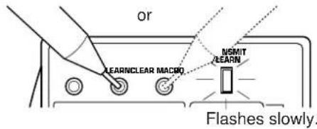
2 Press and hold the CLEAR button using the point of a mechanical pencil, etc.
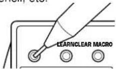
3 Holding the CLEAR button pressed, press and hold the key whose function you want to clear until the indicator flashes 3 times.
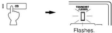
To clear two or more functions sequentially, do not release the CLEAR button pressed, and repeat this step.
Note
If you clear a learned function of a key, the originally preset function of the key is restored (except the keys which are originally preset with no function.)
1 Select the kind of key functions all of which you want to clear by using the MACRO switch on the side panel of the remote control transmitter.

OFF: Select this position if you want to clear all of the learned functions except macros.
QUICK: Select this position if you want to clear all of the macros you made.
SLOW: Select this position if you want to clear all of the learned functions including macros.
2 Press the CLEAR button using the point of a mechanical pencil, etc.
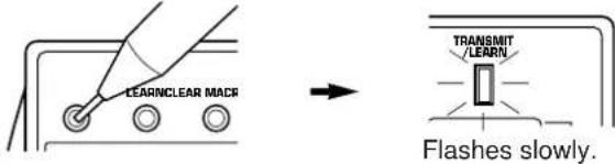
* If one of the following operation is made after you press the CLEAR button, the TRANSMIT/LEARN indicator flashes rapidly and the current mode is canceled. If this occurs, press the CLEAR button again.
• MACRO switch is switched to another position.
• Another key is pressed.
• There is no operation for about 30 seconds.
3 Press and hold the CLEAR button again. While holding the CLEAR button pressed, press and hold the MASTER VOLUME and keys simultaneously until the indicator flashes 7 times.
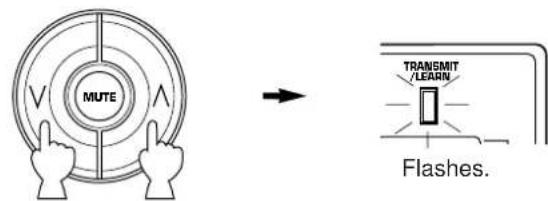
TROUBLESHOOTING
If the unit fails to operate normally, check the following points to determine whether the fault can be corrected by the simple measures suggested. If it cannot be corrected, or if the fault is not listed in the SYMPTOM column, disconnect the power cord and contact your authorized YAMAHA dealer or service center for help.
General
| SYMPTOM | CAUSE | REMEDY |
| The unit fails to turn on when the STANDBY/ON switch is pressed, or turns into the standby mode suddenly soon after the power is turned on. | Power cord is not plugged in or is not completely inserted. | Firmly plug in the power cord. |
| The IMPEDANCE SELECTOR switch on the rear panel is not set to either end closely. | Set the switch to either end closely. | |
| It happens that this unit does not work normally. | There is an influence of strong external noise (lightning, excessive static electricity, etc.) or a misoperation on this unit while using this unit. | Turn this unit into the standby mode and disconnect the AC power cord from the AC outlet. After about 30 seconds have passed, connect the power and operate this unit again. |
| No sound or no picture. | Incorrect output cord connections. | Connect the cords properly. If the problem persists, the cords may be defective. |
| Appropriate input source is not selected. | Select the appropriate input source with the INPUT SELECTOR or the TAPE 2 MON/EXT. DECODER button. | |
| Speaker connections are not secure. | Secure the connections. | |
| Digital signals other than PCM audio and the Dolby Digital (AC-3) (or the DTS) encoded signals which this unit cannot reproduce are input to this unit by playing a CD-ROM etc. | Play a source whose signals this unit can reproduce. | |
| No picture | There is no S video terminal connection between this unit and the TV, though S video signals are input to this unit. | Connect this unit's S VIDEO MONITOR OUT terminal to the TV's S video input terminal. |
| The sound suddenly goes off. | The protection circuit has been activated because of short circuit etc. | Turn this unit into the standby mode, and then turn on to reset the protection circuit. |
| The SLEEP timer has functioned. | Cancel the SLEEP timer function. | |
| Only one side speaker outputs the sound. | Incorrect setting of the BALANCE control. | Adjust it to the appropriate position. |
| Incorrect cord connections. | Connect the cords properly. If the problem persists, the cords may be defective. | |
| No sound from the effect speakers. | The EFFECT button is set off. | Press the EFFECT button to turn it on. |
| A Dolby Surround (or DTS) decoding program is being used with material not encoded with Dolby Surround (or DTS). | Use a different sound field program. | |
| No sound from the front effect speakers. | The function "1E. FRONT MIX" in the SET MENU mode is set to the "ON-5ch" position. | Set to the "OFF-7ch" position. |
| PRO LOGIC/Normal, DOLBY DIGITAL/ Normal or DTS DIGITAL SUR./Normal of the DSP program No. 12 is selected. | Select another program (or subprogram). | |
| No sound from the center speaker. | The function "1A. CENTER SP" in the SET MENU mode is set to the "NONE" position. | Select the appropriate position. |
| One of the DSP programs No. 1 to No. 6 is selected when the input signal of source is 2-channel stereo (analog/PCM). | Select another program. | |
| The input signals of source encoded with the Dolby Digital (AC-3) or the DTS do not have center channel signals. | Refer to the instructions for the source currently played. | |
| Poor bass reproduction. | The function "1D. LFE/BASS OUT" in the SET MENU mode is set in the SWFR or BOTH position, though your system does not include a subwoofer. | Select the MAIN position. |
| Output mode selection for each channel (MAIN, CENTER or REAR) is improper. | Make output mode selections suitable for your speaker system. | |
| Sound "hums". | Incorrect cord connections. | Firmly connect the audio plugs. If the problem persists, the cords may be defective. |
| No connection from the turntable to the GND terminal. | Make the GND connection between the turntable and this unit. | |
| The volume level is low while playing a record. | The record is being played on a turntable with an MC cartridge. | The player should be connected to the unit through the MC head amplifier. |
| The volume level cannot be increased, or sound is distorted. | The component connected to the MD/TAPE 1 REC terminals of this unit is turned off. | Turn on the power to the component. |
| DSP parameters and some other settings on this unit cannot be changed. | The function “9. MEMORY GUARD” in the SET MENU mode is set to the “ON” position. | Set to the “OFF” position. |
| “INPUT DATA ERROR” appears on the display and no sound is heard. | A nonstandardized source is played back, or the unit playing back a source is misoperating. | Check the source, or turn off the unit playing back the source and then turn on again. |
| The sound field cannot be recorded. | It is not possible to record the sound field on a tape deck connected to this unit’s MD/TAPE 1 REC terminals. | |
| This unit do not operate properly. | The internal microcomputer has been frozen by an external electric shock (lightning, excessive static electricity, etc.) or power supply with low voltage. | Unplug the AC power cord from the wall AC outlet, and then plug in again after about one minute. |
| A source cannot be recorded by a tape deck or VCR connected to this unit. | The source unit is connected to this unit between digital terminals only. | Make additional connection between analog terminals. |
| Noise from nearby TV or tuner. | This unit is too close to the affected equipment. | Move the unit further away from the affected equipment. |
| The sound is degraded when listening with the headphones connected to the compact disc player or tape deck that are connected with this unit. | This unit is in the standby mode. | Turn the power to this unit on. |
Remote control transmitter
| SYMPTOM | CAUSE | REMEDY |
| The remote control transmitter does not work. | The batteries of this remote control transmitters are weak. | Replace the batteries with new ones and press the RESET button on the remote control transmitter. |
| The internal microcomputer “freezes”. | Press the RESET button on the remote control transmitter. | |
| The remote control transmitter does not function properly. | Wrong distance or angle. | The remote control transmitter will function from a maximum range of 6 meters, no more than 30 degrees off-axis from the front panel. |
| Direct sunlight or lighting (of an inverter type of fluorescent lamp etc.) is striking the remote control sensor of the main unit. | Change position of the main unit. | |
| The internal microcomputer “freezes”. | Press the RESET button on the remote control transmitter. | |
| Learning cannot be made successfully. (The TRANSMIT/LEARN indicator does not light up or flash.) | The batteries of this remote control transmitter and/or the other remote control transmitter are weak. | Replace the batteries (and press the RESET button for this remote control transmitter). |
| The distance between the two remote control transmitters is too long or too short. | Place the remote control transmitters with the proper distance. | |
| The signal coding or modulation of the other remote control transmitter is not compatible with this remote control transmitter. | Learning is not possible. | |
| Memory capacity is full. | Further learning is not possible without deleting unnecessary commands. | |
| The internal microcomputer “freezes”. | Press the RESET button on the remote control transmitter. | |
| Continuous functions such as volume are learned, but operate only for a moment before stopping. | Learning process incomplete. | Be sure to press and hold the function key on the other remote control transmitter until the TRANSMIT/LEARN indicator begins flashing slowly. |
When playing back a source encoded with the DTS:
| SYMPTOM | CAUSE | REMEDY |
| A loud hissing noise is heard when you play back a source encoded with the DTS. | The player which plays back the source is not connected to a digital audio signal input terminal of this unit. | The player must be connected to a digital audio signal input terminal of this unit besides analog audio signal terminal connections. |
| The “ANALOG” input mode is selected on this unit. | Select a proper input mode on this unit to turn on the DTS decoder built into this unit. | |
| A percussive noise is heard when you begin playing back a source encoded with the DTS. | If the “AUTO” input mode is selected, depending on some sources, there may be a case that a noise is heard while this unit is identifying the format of input signal. | Set the input mode of the currently selected input source to “DTS”. |
| No sound is heard when you play back a source encoded with the DTS, even though the “AUTO” or “DTS” input mode is selected on this unit. | The DTS decoder built into this unit does not function because the player has a digital volume control and it is set at a position other than “maximum”, “neutral” or “ineffective”. | Set the player’s digital volume control at the maximum, neutral or ineffective position. |
| No sound is heard when you play back an MD onto which you have recorded a source encoded with the DTS. | A source encoded with the DTS cannot be recorded onto an MD. | |
| No sound is heard when you play back a DAT onto which you have recorded a source encoded with the DTS. | Depending on a DAT deck, a source encoded with the DTS cannot be recorded onto a DAT. | |
| No sound is heard when you play back a source (CD etc.) even though the currently selected input mode is “AUTO”. | In the “AUTO” mode, the DTS-decoding mode cannot be changed to the normal (PCM) digital signal input mode automatically. | Press the INPUT MODE button on the front panel or the input selector button (for the currently selected source) on the remote control transmitter so that “PCM” appears on the display. |
Notes
- It is necessary to use a DTS decoder to play back a source encoded with the DTS, so the player which plays back a source must be connected to a digital audio input terminal of this unit in the way described in this manual. If this connection is not made or only a D/A converter is used without using a DTS decoder, when you play back a source, only a loud hiss noise will be heard.
- If you make a search (or skip etc.) operation while playing back a source encoded with the DTS, the "PCM" indicator lights up on the display. This is because this unit automatically changes the DTS-decoding mode to the normal (PCM) digital signal input mode to prevent a noise from being output.
- A source encoded with the DTS cannot be recorded onto analog audio and video tapes, and also, an analog tape recorded with a source encoded with the DTS cannot be played back.
The same result is obtained for MDs and DATs (depending on a DAT deck used for recording and/or playback).
SPECIFICATIONS
Minimum RMS Output Power Per Channel
(When both channels are driven)
MAIN L/R (20 Hz to 20 kHz, 0.015% THD, 8Ω)
110W+110W
CENTER (20 Hz to 20 kHz, 0.015% THD, 8Ω) ..... 110W
REAR L/R (20 Hz to 20 kHz, 0.015% THD, 8Ω)
110W+110W
FRONT L/R (1 kHz, 0.05% THD, 8Ω)....35W+35W
Maximum Power [China and General models only]
1 kHz, 10% THD, 6Ω (When both channels are driven)
MAIN L/R....150W+150W
CENTER 150W
REAR L/R....150W+150W
FRONT L/R....45W+45W
Dynamic Power Per Channel
(by IHF Dynamic Headroom Measuring Method)
[U.S.A., Canada, China and General models only]
MAIN L/R (8Ω/6Ω/4Ω)
(When both channels are driven).... 150W/180W/240W
Dynamic Headroom
[U.S.A., Canada, China and General models only]
MAIN L/R (8Ω) 1.3 dB
DIN Standard Output Power Per Channel [Europe and U.K. models only]
MAIN L/R (1 kHz, 0.7% THD, 4Ω)
(When both channels are driven).... 180W
IEC Power [Europe and U.K. models only]
MAIN L/R (1 kHz, 0.015% THD, 8Ω)
(When both channels are driven).... 120W
Damping Factor
MAIN L/R, CENTER (20 Hz to 20 kHz, 8Ω)
More than 200
Input Sensitivity/Impedance (100W/8Ω)
CD/TUNER/MD·TAPE 1/TAPE 2/LD/TV·DBS/VCR 1
/VCR 2/DVD·VCR 3/VIDEO AUX.... 150 mV/47 kΩ
PHONO MM....2.5 mV/47 kΩ
MAIN IN 1V/47 kΩ
Maximum Input Signal (1 kHz, 0.05% THD, EFFECT ON)
CD/TUNER/MD·TAPE 1/TAPE 2/LD/TV·DBS/VCR 1
/VCR 2/DVD·VCR 3/VIDEO AUX 2.3V
PHONO MM 130 mV
Output Level/Impedance
REC OUT.... 150 mV/1.5 kΩ
PRE OUT
MAIN, CENTER, REAR, FRONT 1V/1.2 kΩ
SUBWOOFER (SPLIT L, R) (EFFECT OFF) 1.2V/1.2 kΩ
SUBWOOFER (MONO) (EFFECT OFF) 2V/1.2 kΩ
Maximum Voltage Output (20 Hz to 20 kHz, 1% THD)
PRE OUT (MAIN L/R) ...... More than 3V
Headphone Jack Rated Output/Impedance
Output Level
(CD/TUNER/MD·TAPE 1/TAPE 2/LD/TV·DBS/VCR 1
/VCR 2/DVD·VCR 3/VIDEO AUX Input: 50 mV, RL=8Ω)
0.2V
Impedance 100Ω
Frequency Response (20 Hz to 20 kHz)
CD/TUNER/MD·TAPE 1/TAPE 2/LD/TV·DBS/VCR 1
/VCR 2/DVD·VCR 3/VIDEO AUX to MAIN L/R SP OUT 0±0.5 dB
RIAA Equalization Deviation (20 Hz to 20 kHz)
PHONO MM....0±0.5 dB
Total Harmonic Distortion (20 Hz to 20 kHz)
CD/TUNER/MD·TAPE 1/TAPE 2/LD/TV·DBS/VCR 1
/VCR 2/DVD·VCR 3/VIDEO AUX to PRE OUT (MAIN L/R),
1V.... Less than 0.005%
PHONO MM to REC OUT, 3V .... Less than 0.01%
MAIN IN to SP OUT (MAIN L/R, CENTER), 40W/8Ω
Less than 0.005%
MAIN IN to SP OUT (MAIN L/R, CENTER), 50W/6Ω
Less than 0.008%
Signal-to-Noise Ratio (IHF-A Network)
CD/TUNER/MD·TAPE 1/TAPE 2/LD/TV·DBS/VCR 1
/VCR 2/DVD·VCR 3/VIDEO AUX (Input Shorted 150 mV)
(EFFECT OFF) More than 96 dB
PHONO MM (Input Shorted 5 mV) (EFFECT OFF)
More than 86 dB
Residual Noise (IHF-A Network)
MAIN L/R SP OUT.... Less than 150 ∞V
Channel Separation (Vol -30 dB)
CD/TUNER/MD·TAPE 1/TAPE 2/LD/TV·DBS/VCR 1
/VCR 2/DVD·VCR 3/VIDEO AUX Input 5.1 kΩ Shorted
(EFFECT OFF) 1 kHz/10 kHz ...... More than 70 dB/60 dB
PHONO MM Input Shorted (EFFECT OFF)
1 kHz/10 kHz.....More than 70 dB/60 dB
Tone Control Characteristics
Bass
Boost/Cut ±10 dB (50 Hz)
Turnover frequency 350 Hz
Treble
Boost/Cut ±10 dB (20 kHz)
Turnover frequency 3.5 kHz
Center Channel Graphic Equalizer
Frequency 100 Hz/300 Hz/1 kHz/3 kHz/10 kHz
Boost/Cut ±6 dB
Q 0.7
Bass Extension (MAIN L/R) ....+6 dB (70 Hz)
Low Pass Filter Characteristics
SUBWOOFER (fc = 90 Hz) 24 dB/oct.
CINEMA Equalizer
High-shelving filter Frequency .... 1.0 kHz to 12.7 kHz Boost/Cut .... -9 dB to +6 dB
Parametric equalizer Frequency .... 1.0 kHz to 12.7 kHz Boost/Cut .... -9 dB to +6 dB Q .... 1.85
Audio Muting -20 dB
Video Section
Video Signal Type [U.S.A. and Canada Models]....NTSC [Europe, U.K. and Australia models]....PAL [China and General Models]....NTSC/PAL Video Signal Level ....1 Vp-p/75Ω S-Video Signal Level Y....1 Vp-p/75Ω C....0.286 Vp-p/75Ω Maximum Input Level ....More than 1.5 Vp-p Signal-to-Noise Ratio ....More than 50 dB Monitor Out Frequency Response .....5 Hz to 10 MHz, -3 dB
Power Supply
[U.S.A. and Canada models] ..... AC 120V/60 Hz [Europe and U.K. models] ..... AC 230V/50 Hz [Australia model] ..... AC 240V/50 Hz [China and General models] ..... AC 110/120/220/240V 60/50 Hz
Power Consumption
[U.S.A., Europe, U.K., Australia, China and General models] 500W [Canada model] 500W/650 VA
AC Outlets
2 SWITCHED OUTLETS [U.S.A. model] .... 120W max. total [Canada, China and General models] .... 100W max. total 1 SWITCHED OUTLET [Europe, U.K. and Australia models] .... 100W max. 1 UNSWITCHED OUTLET [U.S.A. and Canada models] .... 180W max. [China and General models] .... 200W max.
Dimensions (W x H x D)
[U.S.A., Canada, Europe, U.K. and Australia models] 435 x 190.5 x 473 mm (17-1/8" x 7-1/2" x 18-5/8") [China and General models (without side panels)] 435 x 190.5 x 473 mm (17-1/8" x 7-1/2" x 18-5/8") [China and General models (with side panels)] 473 x 190.5 x 473 mm (18-5/8" x 7-1/2" x 18-5/8")
Weight
[U.S.A., Canada, Europe, U.K. and Australia models] .... 23.0 kg (50.6 lbs.) [China and General models (without side panels)] .... 23.0 kg (50.6 lbs.) [China and General models (with side panels)] .... 25.0 kg (55 lbs.)
Accessories......Remote control transmitter Batteries User function stickers
* Specifications are subject to change without notice.
TABLES DES MATIERES
ACCESSOIRES FOURNIS
REPRODUCTION D'UNE SOURCE .... 39
ENREGISTREMENT D'UNE SOURCE SUR UNE BANDE
MAGNETIQUE (OU UN MINIDISQUE) (OU POUR
EFFECTUER LA DUPLICATION D'UNE BANDE SUR
UNE AUTRE) 42
CONTROLE SONORE DE CET APPAREIL 44
UTILISATION DU PROCESSEUR DE CHAMP
SONORE NUMERIQUE (DSP) 45
REPRODUCTION D'UNE SOURCE AVEC UN EFFET
DE CHAMP SONORE NUMERIQUE (DSP) 45
REGLAGE DU NIVEAU DE SORTIE DES ENCEINTES
CENTRALE, ARRIERE DROITE, ARRIERE GAUCHE,
D'EFFET AVANT, ET DU SUBWOOFER 48
BREF APERÇU DES PROGRAMMES DE CHAMP
natural_image
Simple line drawing of a device inside a rounded rectangular frame with three dots above (no text or symbols)natural_image
Abstract diagram with three overlapping circles and a central rectangular block containing an apple icon (no text or symbols)INSTALLATION DES ENCEINTES ACOUSTIQUES
natural_image
Diagram of a robot with motion lines and a central device (no text or symbols)La configuration la plus simple
natural_image
Diagram showing wireless signal waves around a central device with no text or symbolsnatural_image
Diagram of a device with four square blocks and a central monitor icon, no text or symbols presentnatural_image
Diagram showing wireless signal waves interacting with a central icon depicting a person (no text or symbols)natural_image
Diagram of a mechanical assembly with multiple cylindrical components connected to a cable (no text or symbols)① Bornes de pré-sortie/entrée de canal principal (MAIN CH PRE OUT/MAIN IN)
natural_image
Diagram showing two-step installation of a wall-mounted device with circular components, no text or symbols presentnatural_image
Line drawing of a hand pressing down on a computer monitor (no text or symbols)PANNEAU D'AFFICHAGE
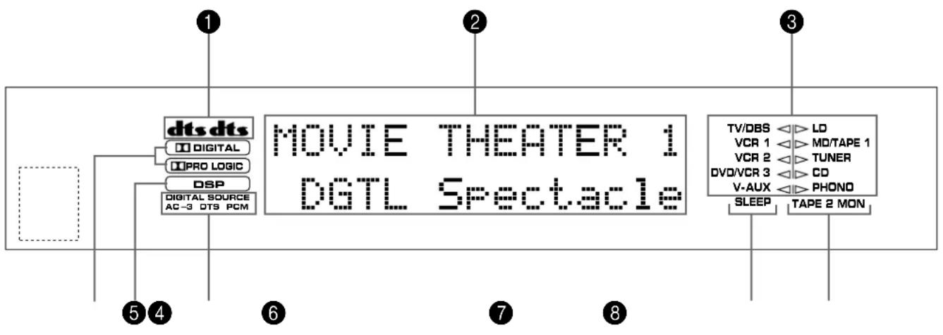
flowchart
graph TD
    A["dts dts"] --> B["Digital"]
    A --> C["PRO LOGIC"]
    A --> D["DSP"]
    A --> E["Digital Source AC-3 DTS PCM"]
    F["MOVIE THEATER 1 DGTL Spectacle"] --> G["TV/DBS"]
    F --> H["VCR 1"]
    F --> I["VCR 2"]
    F --> J["DVO/VCR 3"]
    F --> K["V-AUX"]
    F --> L["SLEEP"]
    F --> M["LD"]
    F --> N["MD/TAPE 1"]
    F --> O["TUNER"]
    F --> P["CD"]
    F --> Q["PHONO"]
    F --> R["TAPE 2 MON"]
1 Indicateurds
Choix: LARGE (LRG)/SMALL (SML)/NONE
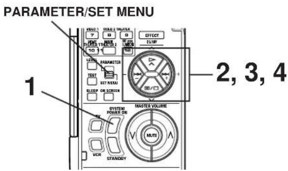
Télécommande
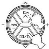
- SPEAKER SET Press +/- Key 1 TWISS B=LO VER 1 VOTARS 1 VER 2 TUNER OVALOR 3 CO VAUX PHONE
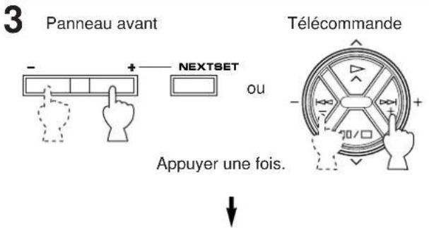
1A. CENTER SP ▶ LRG SML NONE TVDBS VCR 1 VCR 2 DVCKR 3 V AUX ▶ LD MOTAGE 1 TUNES CC PHONO
10
line
| Fréquence (Hz) | GAIN (dB) | | -------------- | --------- | | 20 | 0 | | 50 | 0 | | 100 | 0 | | 200 | 0 | | 500 | 0 | | 1k | 0 | | 2k | 0 | | 5k | 0 | | 10k | 0 | | 20k | 0 | | 30k | -9 | | 40k | -6 | | 50k | -3 | | 60k | 0 | | 70k | 3 | | 80k | 6 | | 90k | 3 | | 100k | 0 | | 110k | -3 | | 120k | -6 | | 130k | -9 | | 140k | -6 | | 150k | -3 | | 160k | 0 | | 170k | 3 | | 180k | 6 | | 190k | 3 | | 200k | 0 |REPRODUCTION D'UNE SOURCE

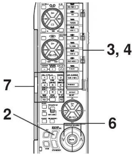
natural_image
Simple diagram of two concentric circles with curved arrows indicating rotation or direction (no text or symbols)Télécommande
ou
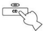
• S. DELAY (retard surround)
natural_image
Simple line drawing of a device with a handle and control panel (no text or symbols)12 Touche de volume principal haut/bas (MASTER VOLUME ^ et ∨)
natural_image
Diagram showing a device with two circular components connected to a rectangular control panel (no text or symbols)SUBWOOFER (SPLIT L, R) (EFFECT OFF)
1,2V/1,2 kΩ
SUBWOOFER (MONO) (EFFECT OFF) ...... 2V/1,2 kΩ
Accentuation/Coupure ±10 dB (50 Hz)
Accentuation/Coupure .... ±10 dB (20 kHz)
Accentuation/Coupure .... ±6 dB
Q 0,7
Extension des basses (MAIN L/R) ..... +6 dB (70 Hz)
SUBWOOFER (fc = 90 Hz) 24 dB/oct.
Egaliseur CINEMA
Dimensions (L x H x P)
DTS Digital Surround
natural_image
Simple line drawing of a device with a flame symbol inside, enclosed in a gray rounded rectangle (no text or symbols)natural_image
Abstract diagram with three overlapping circles and a central rectangular box containing a flame icon (no text or symbols)natural_image
Diagram showing a vehicle with sensor waves and a battery icon, no text or symbols presentEinfachstes System
natural_image
Diagram showing wireless signal waves interacting with a central device (no text or symbols)natural_image
Diagram showing four black squares with sound waves and a central icon resembling a TV or alarm device (no text or symbols)natural_image
Diagram showing wireless signal waves interacting with a central device (no text or symbols)natural_image
Diagram of a mechanical assembly with multiple cylindrical components connected to a cable (no text or symbols)natural_image
Diagram showing hand positioning a component before and after assembly, with no visible text or symbolsSchließen
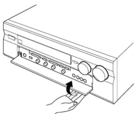
natural_image
Line drawing of a hand pressing down on a computer control panel (no text or symbols)ANZEIGEFELD

flowchart
graph TD
    A["dts dts"] --> B["Digital"]
    A --> C["PRO LOGIC"]
    A --> D["DSP"]
    A --> E["Digital Source AC-3 DTS PCM"]
    F["MOVIE THEATER 1 DGTL Spectacle"] --> G["TV/DBS LD"]
    F --> H["VCR 1 MD/TAPE 1"]
    F --> I["VCR 2 TUNER"]
    F --> J["DVD/VCR 3 CD"]
    F --> K["V-AUX PHONO"]
    F --> L["SLEEP TAPE 2 MON"]
① dts -Anzeigen
10
line
| Frenz (Hz) | GAIN (dB) | | ---------- | --------- | | 20 | 0 | | 50 | 0 | | 100 | 0 | | 200 | 0 | | 500 | 0 | | 1k | 0 | | 2k | 0 | | 5k | 0 | | 10k | 0 | | 20k | 0 | | High | 0 | | PEQ | -3 |Frequenzgang
line
| Frequency (Hz) | Gain (dB) | | -------------- | --------- | | 20 | 0 | | 50 | 0 | | 100 | 0 | | 200 | 0 | | 500 | 0 | | 1k | 0 | | 2k | 0 | | 5k | 0 | | 10k | 0 | | 20k | 0 | | 30k | -9 | | 40k | -6 | | 50k | -3 | | 60k | 0 | | 70k | 3 | | 80k | 6 | | 90k | 3 | | 100k | 0 | | 110k | -3 | | 120k | -6 | | 130k | -9 | | 140k | -6 | | 150k | -3 | | 160k | 0 | | 170k | 3 | | 180k | 6 | | 190k | 3 | | 200k | 0 |PEQ: FRQ ..... 1,0 kHz bis 12,7 kHz GAIN ..... +6 dB/-9 dB

line
| Frequency (Hz) | Gain (dB) | | -------------- | --------- | | 1.0k | +6 | | 1.2k | +3 | | 1.6k | +0 | | 2.0k | -3 | | 2.5k | -6 | | 3.2k | -9 | | 4.0k | -6 | | 5.0k | -3 | | 5.7k | 0 | | 6.3k | +3 | | 7.1k | +6 | | 8.0k | +3 | | 9.0k | +0 | | 10.1k | -3 | | 11.3k | -6 | | 12.7kHz | -9 |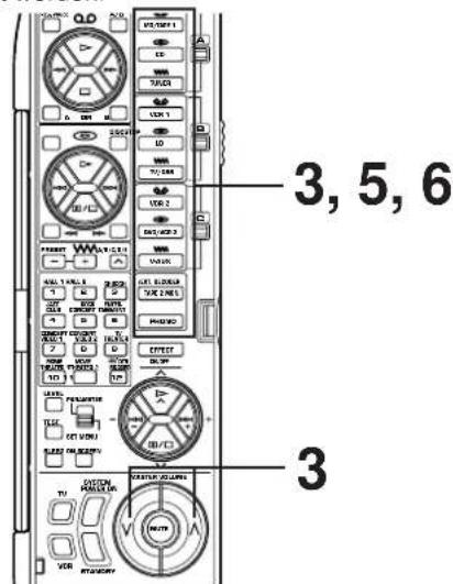
natural_image
Simple circular diagram with two curved arrows indicating rotational or cyclical motion (no text or symbols)oder
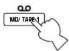
DIGITALER KLANGFELDPROZESSOR (DSP)
→ Hall A in Europe
EFCT TRIM .... Q dB
INIT. DLY···30ms
ROOM SIZE....1/0
LIVENESS....5
WAS IST EIN KLANGFELD?
→ Hall A in Europe EFCT TRIM ....0dB INIT. DLY ....30ms ROOM SIZE .... 1.0 LIVENESS .... 5
] — | Unterprogramm
natural_image
Simple line drawing of a device interior with no text or symbols12 Lautstärketasten (MASTER VOLUME und)
natural_image
Diagram showing a device with two circular switches connected to a control panel (no text or symbols present)Speichersicherung
FRONT L/R (1 kHz, 0.05% Kliirgrad, 8Ω) .....35W+35W
MAIN L/R....150W+150W
CENTER 150W
REAR L/R....150W+150W
FRONT L/R....45W+45W
SUBWOOFER (SPLIT L, R) (EFFECT OFF)
1,2V/1,2 kΩ
SUBWOOFER (MONO) (EFFECT OFF)
2V/1,2 kΩ
MAIN IN an SP OUT (MAIN L/R, CENTER), 40W/8Ω
MAIN IN an SP OUT (MAIN L/R, CENTER), 50W/6Ω
SUBWOOFER (fc = 90 Hz) 24 dB/Oktave
CINEMA-Equalizer
KORT ÖVERSIKT AV DIGITALA
LJUDFÄLTSPROGRAM 50
VISNING PÅ MONITORSKÄRMEN 55
HUR DU SKAPAR EGNA LJUDEFFEKT-
PROGRAM 56
HUR DU SKAPAR EGNA LJUDEFFEKT- PROGRAM 57
BESKRIVNING AV DE DIGITALA LJUDFÄLTSPARAMETRARNA 58
INSTÄLLNING AV INSOMNINGSFUNKTIONEN ...... 61
FJÄRRKONTROLLEN 62
ANMÄRKNINGAR OM FJÄRRKONTROLLEN
Byte av batteri
DTS Digital Surround
natural_image
Simple line drawing of a device with three dots above and a fruit icon inside, enclosed in a large gray rounded rectangle (no text or symbols)natural_image
Abstract diagram with three overlapping circles and a central rectangular block containing a flame icon (no text or symbols)HÖGTALARUPPSTÄLLNING
natural_image
Diagram showing a device emitting sound waves with no text or symbolsDet enklaste systemet.
natural_image
Diagram showing wireless signal propagation around a central device (no text or symbols)natural_image
Diagram showing four black squares with sound waves and a central icon resembling a TV or megaphone (no text or symbols)natural_image
Diagram showing wireless signal waves interacting with a central icon depicting a person (no text or symbols present)natural_image
Diagram of three cylindrical connectors connected by a cable, with no visible text or symbolsnatural_image
Diagram showing hand positioning a wall-mounted device before and after adjustment, with no text or symbols present.natural_image
Line drawing of a hand inserting a device into a rack with buttons and a scroll (no text or symbols)DISPLAY

flowchart
graph TD
    A["dts dts"] --> B["Digital"]
    A --> C["PRO LOGIC"]
    A --> D["DSP"]
    A --> E["Digital Source AC-3 DTS PCM"]
    F["MOVIE THEATER 1 DGTL Spectacle"] --> G["TV/DBS"]
    F --> H["VCR 1"]
    F --> I["VCR 2"]
    F --> J["DV0/VCR 3"]
    F --> K["V-AUX"]
    F --> L["SLEEP"]
    F --> M["TAPE 2 MON"]
    N["1"] --> A
    O["2"] --> F
    P["3"] --> F
    Q["4"] --> A
    R["5"] --> A
    S["6"] --> A
    T["7"] --> F
    U["8"] --> F
ATT VÄLJA UTGÅNGSFUNKTIONER SOM PASSAR DINA HÖGTALARE (I SET MENU-FUNKTIONEN)

1A. CENTER SP ▶ LRG SML NONE TVDBS VCR 1 VCR 2 DVCKR 3 V AUX ▶ LD MOTAGE 1 TUNES CC PHONO
line
| Frekvens (Hz) | Gain (dB) | | ------------- | --------- | | 20 | 0 | | 50 | 0 | | 100 | 0 | | 200 | 0 | | 500 | 0 | | 1k | -1 | | 2k | -2 | | 5k | -3 | | 10k | -4 | | 20k | -5 | | 5000 | -6 | | 1k | -7 | | 2k | -8 | | 5k | -9 | | 10k | -8 | | 20k | -7 | | 5000 | -6 | | 1k | -5 | | 2k | -4 | | 5k | -3 | | 10k | -2 | | 20k | -1 | | 5000 | 0 | | 1k | +6 | | 2k | +5 | | 5k | +4 | | 10k | +3 | | 20k | +2 | | 5000 | +1 | | 1k | +0 | | 2k | -1 | | 5k | -2 | | 10k | -3 | | 20k | -4 | | 5000 | -5 | | 1k | -6 | | 2k | -7 | | 5k | -8 | | 10k | -9 | | 20k | -8 | | 5000 | -7 | | 1k | -6 | | 2k | -5 | | 5k | -4 | | 10k | -3 | | 20k | -2 | | 5000 | -1 | | 1k | 0 | | 2k | +6 | | 5k | +5 | | 10k | +4 | | 20k | +3 | | 5000 | +2 | | 1k | +1 | | 2k | +0 | | 5k | -1 | | 10k | -2 | | 20k | -3 | | 5000 | -4 | | 1k | -5 | | 2k | -6 | | 5k | -7 | | 10k | -8 | | 20k | -9 | | 5000 | -8 | | 1k | -7 | | 2k | -6 | | 5k | -5 | | 10k | -4 | | 20k | -3 | | 5000 | -2 | | 1k | -1 | | 2k | 0 | | 5k | +1 | | 10k | +2 | | 20k | +3 | | 5000 | +4 | | 1k | +5 | | 2k | +6 | | 5k | +5 | | 10k | +4 | | 20k | +3 | | 5000 | +2 | | 1k | +1 | | 2k | +0 | | 5k | -1 | | 10k | -2 | | 2O | -3 | | 5O | -4 | | 1O | -5 | | 2O | -6 | | 5O | -7 | | 1O | -8 | | 2O | -9 | | 5O | -8 | | 1O | -7 | | 2O | -6 | | 5O | -5 | | 1O | -4 | | 2O | -3 | | 5O | -2 | | 1O | -1 | | 2O | 0 | | 5O | +1 | | 1O | +2 | | 2O | +3 | | 5O | +4 | | 1O | +5 | | 2O | +6 | | 5O | +5 | | 1O | +4 | | 2O | +3 | | 5O | +2 | | 1O | +1 | | 2O | +0 | | 5O | -1 | | 1O | -2 | | 2O | -3 | | 5O | -4 | | 1O | -5 | | 2O | -6 | | 5O | -7 | | 1O | -8 | | 2O | -9 | | | Overlap | +6 | | Overlap | +5 | | Overlap | +4 | | Overlap | +3 | | Overlap | +2 | | Overlap | +1 | | Overlap | +0 | | Overlap | -1 | | Overlap | -2 | | Overlap | -3 | | Overlap | -4 | | Overlap | -5 | | Overlap | -6 | | Overlap | -7 | | Overlap | -8 | | Overlap | -9 |HIGH: FRQ .... 1,0 kHz till 12,7 kHz
GAIN +6 dB/-9 dB

natural_image
Simple diagram of two concentric circles with curved arrows indicating rotation or direction (no text or symbols)eller
Fjärrkontrollen
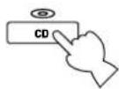
natural_image
Simple circular diagram with two curved arrows indicating rotational or cyclical motion (no text or symbols)eller
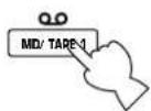
→ Hall A in Europe
EFCT TRIM .... Q dB
INIT. DLY···30ms
ROOM SIZE....1/0
LIVENESS....5
→ Hall A in Europe EFCT TRIM ····0dB INIT. DLY ····30ms ROOM SIZE ····1.0 LIVENESS ······5
Sekundärprogram
4
• INIT. DLY (Initial Delay)
KNAPPARNAS OCH OMKOPPLARNAS NAMN OCH DERAS FUNKTIONER

natural_image
Simple line drawing of a device casing with a handle and base, no text or symbols presentwww (radiovåg): vanlig tuner, TV/Satellittuner, etc.
natural_image
Diagram showing a device with two circular components connected to a rectangular control panel (no text or symbols present)FRONT L/R (1 kHz, 0,05% THD, 8Ω)....35W+35W
MAIN L/R....150W+150W
CENTER 150W
REAR L/R....150W+150W
FRONT L/R....45W+45W
MAIN L/R (1 kHz, 0,7% THD, 4Ω)
(Med bâda kanalerna drivna) 180W
PHONO MM Korslutna ing. (EFFECT OFF)
1 kHz/10 kHz......Mer än 70 dB/60 dB
SUBWOOFER (fc = 90 Hz) 24 dB/oct.
CINEMA-equalizer
High-shelving-filter
Frekvens 1,0 kHz till 12,7 kHz
Förstärkning/Dämpning ...... -9 dB till +6 dB
Parametrisk equalizer
Frekvens 1,0 kHz till 12,7 kHz
Förstärkning/Dämpning ...... -9 dB till +6 dB
Q 1,85
Ljuddämpning ...... -20 dB
Videodelen
natural_image
Simple line drawing of a device inside a rounded rectangular frame with three dots above (no text or symbols)Dolby Digital (AC-3) o DTS + 3 campi sonori digitali
natural_image
Abstract diagram with three gray clover shapes surrounding a central white document icon (no text or symbols)natural_image
Diagram of a robot with four wheels and a central device, no text or symbols presentnatural_image
Diagram showing wireless signal propagation around a central device with no text or symbolsnatural_image
Diagram showing wireless signal waves and a central icon with a fish inside (no text or symbols)Per sorgenti audio e video
natural_image
Diagram showing wireless signal waves interacting with a central object (no text or symbols)■ Collegamento ai terminali VIDEO AUX (terminali ausiliari del pannello anteriore)
flowchart
graph TD
    A["Destro"] --> B["Altoparlanti principali"]
    B --> C["Sinistro"]
    C --> D["Altoparlante centrale"]
    D --> E["Destro"]
    E --> F["Altoparlanti posteriori"]
    F --> G["Sinistro"]
    G --> H["Sistema subwoofer"]
    H --> I["Coupler"]
    I --> J["Front rear (sural) 1"]
    I --> K["Front rear (sural) 2"]
    I --> L["Front rear (sural) 3"]
    I --> M["Front rear (sural) 4"]
    I --> N["Front rear (sural) 5"]
    I --> O["Front rear (sural) 6"]
    I --> P["Front rear (sural) 7"]
    I --> Q["Front rear (sural) 8"]
    I --> R["Front rear (sural) 9"]
    I --> S["Front rear (sural) 10"]
    I --> T["Front rear (sural) 11"]
    I --> U["Front rear (sural) 12"]
    I --> V["Front rear (sural) 13"]
    I --> W["Front rear (sural) 14"]
    I --> X["Front rear (sural) 15"]
    I --> Y["Front rear (sural) 16"]
    I --> Z["Front rear (sural) 17"]
    I --> AA["Front rear (sural) 18"]
    I --> AB["Front rear (sural) 19"]
    I --> AC["Front rear (sural) 20"]
    I --> AD["Front rear (sural) 21"]
    I --> AE["Front rear (sural) 22"]
    I --> AF["Front rear (sural) 23"]
    I --> AG["Front rear (sural) 24"]
    I --> AH["Front rear (sural) 25"]
    I --> AI["Front rear (sural) 26"]
    I --> AJ["Front rear (sural) 27"]
    I --> AK["Front rear (sural) 28"]
    I --> AL["Front rear (sural) 29"]
    I --> AM["Front rear (sural) 30"]
    I --> AN["Front rear (sural) 31"]
    I --> AO["Front rear (sural) 32"]
    I --> AP["Front rear (sural) 33"]
    I --> AQ["Front rear (sural) 34"]
    I --> AR["Front rear (sural) 35"]
    I --> AS["Front rear (sural) 36"]
    I --> AT["Front rear (sural) 37"]
    I --> AU["Front rear (sural) 38"]
    I --> AV["Front rear (sural) 39"]
    I --> AW["Front rear (sural) 40"]
    I --> AX["Front rear (sural) 41"]
    I --> AY["Front rear (sural) 42"]
    I --> AZ["Front rear (sural) 43"]
    I --> BA["Front rear (sural) 44"]
    I --> BB["Front rear (sural) 45"]
    I --> BC["Front rear (sural) 46"]
    I --> BD["Front rear (sural) 47"]
    I --> BE["Back to speaker interface for correct better"]
    BE --> BF["A CENTER B: MA + B / MA OR B"]
natural_image
Diagram of a mechanical assembly with multiple cylindrical components and a connecting rod (no text or symbols)natural_image
Diagram of a mechanical component with a circular end and arrow indicating direction (no text or symbols)natural_image
Diagram showing hand positioning a component before and after assembly, with no visible text or symbolsChiusura
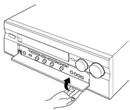
natural_image
Line drawing of a hand inserting a device into a rack with buttons and a scroll (no text or symbols)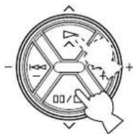
- SPEAKER SET Press +/- Key 1 TWISS BLO VER 1 VOTARS 1 VER 2 TUNER OVALOR 3 CO VAUX PHONE
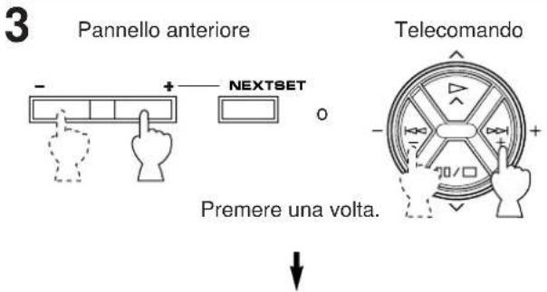
1A. CENTER SP ▶ LRG SML NONE TVDES VOR 1 VOR 2 DUCUM 3 V AUX LD MOTARE 1 TUMER CC PHONO
10
Note
.....da 1,0 kHz a 12,7 kHz
GAIN ....+6 dB/-9 dB

line
| Frenquenza (Hz) | PUNTI DI | FREQUENCY | | --------------- | -------- | --------- | | 20 | 1.0k | +6 | | 50 | 1.2k | +3 | | 100 | 1.6k | +0 | | 200 | 2.0k | -3 | | 500 | 2.5k | -6 | | 1k | 3.2k | -9 | | 2k | 4.0k | -9 | | 5k | 5.0k | -9 | | 10k | 5.7k | -9 | | 20k | 6.3k | -9 | | 500 | 7.1k | -9 | | 1k | 8.0k | -9 | | 2k | 9.0k | -9 | | 5k | 10.1k | -9 | | 10k | 11.3k | -9 | | 20k | 12.7kHz | -9 |PEQ: FRQ 1,0 kHz GAIN da +6 dB a -9 dB
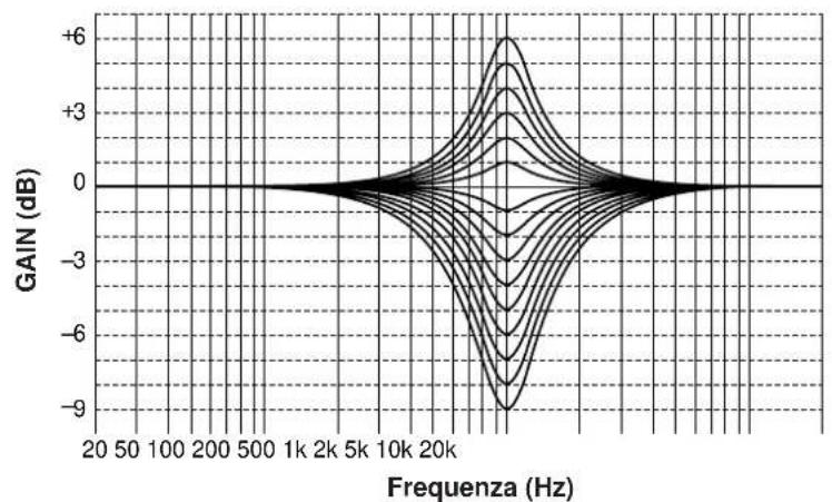
line
| Frequency (Hz) | Gain (dB) | | -------------- | --------- | | 20 | 0 | | 50 | 0 | | 100 | 0 | | 200 | 0 | | 500 | 0 | | 1k | 0 | | 2k | 0 | | 5k | 0 | | 10k | 0 | | 20k | 0 | | 30k | -6 | | 40k | -9 | | 50k | -6 | | 60k | -3 | | 70k | 0 | | 80k | 3 | | 90k | 6 | | 100k | 3 | | 110k | 0 | | 120k | -3 | | 130k | -6 | | 140k | -9 | | 150k | -6 | | 160k | -3 | | 170k | 0 | | 180k | 3 | | 190k | 6 | | 200k | 3 | | 210k | 0 | | 220k | -3 | | 230k | -6 | | 240k | -9 | | 250k | -6 | | 260k | -3 | | 270k | 0 | | 280k | 3 | | 290k | 6 | | 300k | 3 | | 310k | 0 | | 320k | -3 | | 330k | -6 | | 340k | -9 | | 350k | -6 | | 360k | -3 | | 370k | 0 | | 380k | 3 | | 390k | 6 | | 400k | 3 | | 410k | 0 | | 420k | -3 | | 430k | -6 | | 440k | -9 | | 450k | -6 | | 460k | -3 | | 470k | 0 | | 480k | 3 | | 490k | 6 | | 500k | 3 | | 510k | 0 | | 520k | -3 | | 530k | -6 | | 540k | -9 | | 550k | -6 | | 560k | -3 | | 570k | 0 | | 580k | 3 | | 590k | 6 | | 600k | 3 | | 610k | 0 | | 620k | -3 | | 630k | -6 | | 640k | -9 | | 650k | -6 | | 660k | -3 | | 670k | 0 | | 680k | 3 | | 690k | 6 | | 700k | 3 | | 710k | 0 | | 720k | -3 | | 730k | -6 | | 740k | -9 | | 750k | -6 | | 760k | -3 | | 770k | 0 | | 780k | 3 | | 790k | 6 | | 800k | 3 | | 810k | 0 | | 820k | -3 | | 830k | -6 | | 840k | -9 | | 850k | -6 | | 860k | -3 | | 870k | 0 | | 880k | 3 | | 890k | 6 | | 900k | 3 | | 910k | 0 | | 920k | -3 | | 930k | -6 | | 940k | -9 | | 950k | -6 | | 960k | -3 | | 970k | 0 | | 980k | 3 | | 990k | 6 | | 1000k | 3 |PEQ: FRQ .... da 1,0 kHz a 12,7 kHz GAIN ....+6 dB/-9 dB
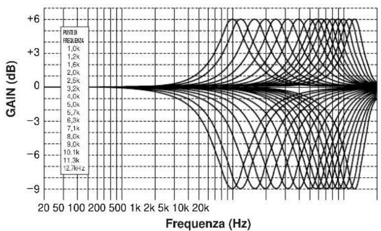
natural_image
Simple diagram of two concentric circles with curved arrows indicating rotation or direction (no text or symbols)0
Telecomando
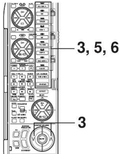
natural_image
Simple diagram of two concentric circles with curved arrows indicating rotation or direction (no text or symbols)Telecomando
0

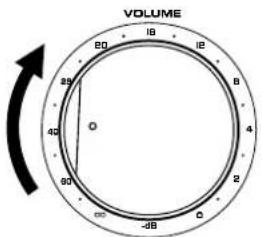
0
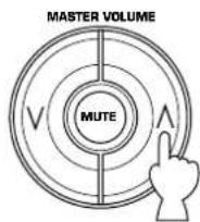
natural_image
Simple circular diagram with two curved arrows indicating rotational or cyclical motion (no text or symbols)0
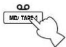
da 1,0 a 5,0 secondi
SUBWOOFER (fc = 90 Hz) 24 dB/oct.
Dimensioni (L x A x P)
[Modelli per gli USA, il Canada, l'Europa, la Gran Bretagna e l'Australie].... 435 x 190,5 x 473 mm
Cambio de pilas
natural_image
Simple line drawing of a device with a fruit icon inside, enclosed in a gray rounded rectangle (no text or symbols)natural_image
Abstract diagram with three overlapping circles and a central rectangular block containing a flame symbol (no text or labels)natural_image
Diagram of a robot with four wheels and a central device, no text or symbols presentnatural_image
Diagram showing wireless signal waves around a central device with no text or symbolsnatural_image
Diagram showing four black squares with sound waves and a central icon resembling a TV or megaphone (no text or symbols)natural_image
Diagram showing wireless signal waves interacting with a central icon depicting a person (no text or symbols)natural_image
Diagram of a mechanical assembly with multiple cylindrical components and a connecting rod (no text or symbols)Sistema da altavoz de graves secundarios
1 Terminales MAIN CH PRE OUT/MAIN IN
8 Interruptor BASS EXTENSION
natural_image
Diagram showing hand positioning of a wall-mounted device before and after adjustment, with no text or symbols present.natural_image
Line drawing of a hand inserting a device into a rack with buttons (no text or symbols)VISUALIZADOR
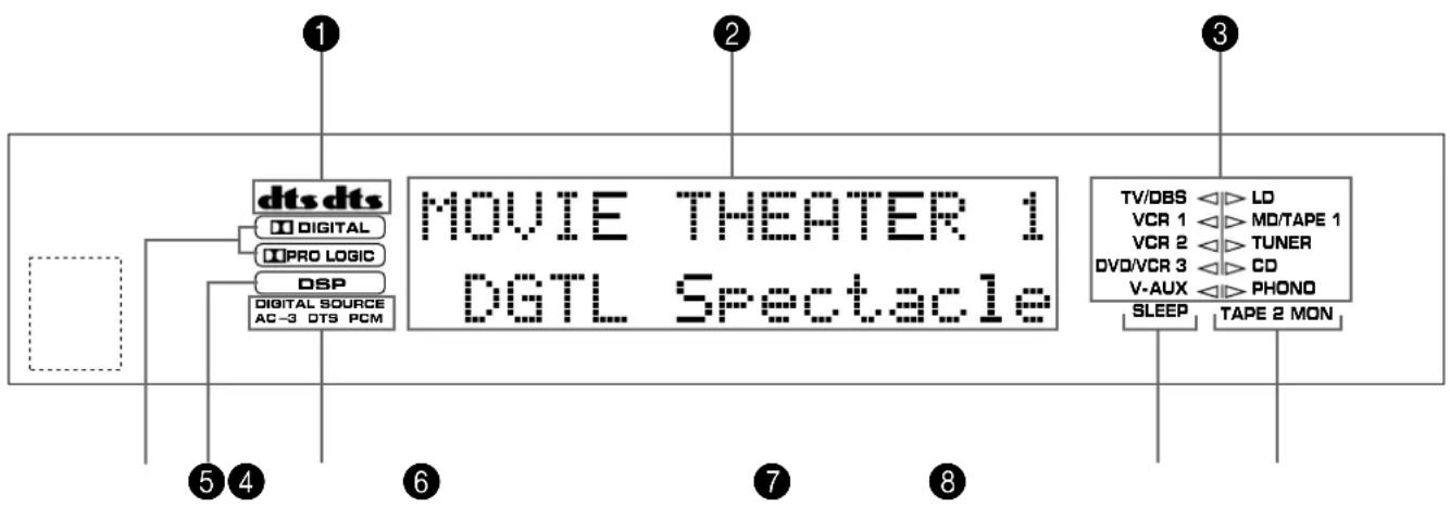
flowchart
graph TD
    A["dts dts"] --> B["Digital"]
    A --> C["PRO LOGIC"]
    A --> D["DSP"]
    A --> E["Digital Source AC-3 DTS PCM"]
    F["MOVIE THEATER 1 DGTL Spectacle"] --> G["TV/DBS"]
    F --> H["VCR 1"]
    F --> I["VCR 2"]
    F --> J["DV0/VCR 3"]
    F --> K["V-AUX"]
    F --> L["SLEEP"]
    F --> M["TAPE 2 MON"]
    N["1"] --> A
    O["2"] --> F
    P["3"] --> F
    Q["4"] --> A
    R["5"] --> A
    S["6"] --> A
    T["7"] --> F
    U["8"] --> F
1 Indicadores
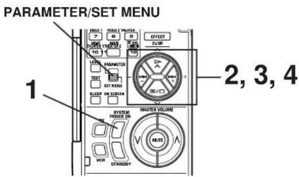
Control remoto
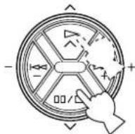
- SPEAKER SET Press +/- Key 1 TWISS B=LO VER 1 VOTARS 1 VER 2 TUNER OVALOR 3 CO VAUX PHONE
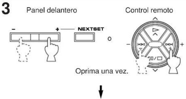
1A. CENTER SP ▶ LRG SML NONE TVDB8 VCR 1 VCR 2 DVCKR 3 V AUX ▶ LC HOTAGE 1 TUNES CC PHONO
Panel delantero
BASS EXTENSION
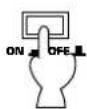
Ajustar a "OFF ( )
5
10
HIGH: FRQ ..... 1,0 kHz a 12,7 kHz
GAIN ....+6 dB/-9 dB
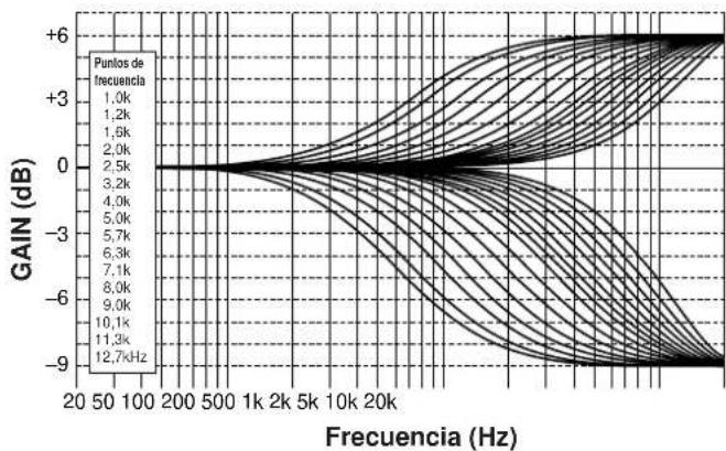
line
| Frecuencia (Hz) | Puntos de frecuencia | | --------------- | --------------------- | | 20 | 1.0k | | 50 | 1.2k | | 100 | 1.5k | | 200 | 2.0k | | 500 | 2.5k | | 1k | 3.2k | | 2k | 4.0k | | 5k | 5.0k | | 10k | 5.7k | | 20k | 6.3k | | 500 | 7.1k | | 1k | 8.0k | | 2k | 9.0k | | 5k | 10.1k | | 10k | 11.3k | | 20k | 12.7kHz |PEQ: FRQ ..... 1,0 kHz a 12,7 kHz
GAIN +6 dB/-9 dB
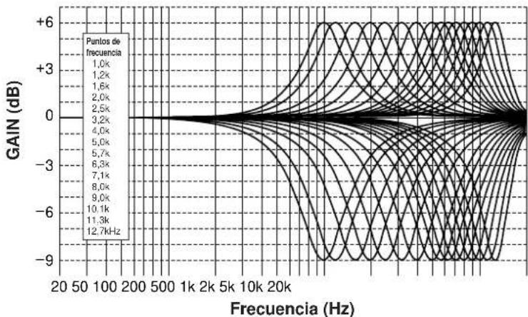
line
| Puntos de frecuencia | Gain (dB) | | --------------------- | --------- | | 1.0k | +6 | | 1.2k | +3 | | 1.6k | +0 | | 2.0k | -3 | | 2.5k | -6 | | 3.2k | -9 | | 4.0k | -6 | | 5.0k | -3 | | 5.7k | 0 | | 6.3k | +3 | | 7.1k | +6 | | 8.0k | +3 | | 9.0k | +0 | | 10.1k | -3 | | 11.3k | -6 | | 12.7kHz | -9 |flowchart
graph TD
    A["MASTER VOLUME"] --> B["MUTE"]
    B --> C["Directional Arrow to MUTE"]
    C --> D["Hand pointing up"]
natural_image
Simple diagram of two concentric circles with curved arrows indicating rotation or direction (no text or symbols)Control remoto

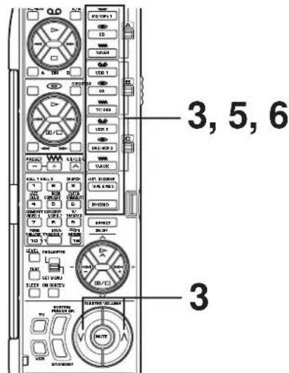
natural_image
Simple diagram of two concentric circles with curved arrows indicating rotation or direction (no text or symbols)0
Control remoto
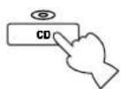
↓
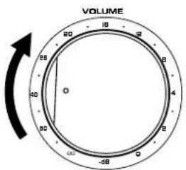
0
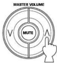
natural_image
Simple circular diagram with two curved arrows indicating rotational or bidirectional motion (no text or symbols)0
Control remoto
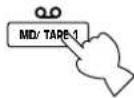
No. 7, 8, 9, 10, 11: principal, central, trasero, efecto delantero
No. 12 (Normal): principal, central, trasero
No. 12 (Enhanced): principal, central, trasero, efecto delantero
natural_image
Diagram showing a device with two circular components connected to a keyboard, no text or symbols presentRespaldo de memoria
SUBWOOFER (fc = 90 Hz) 24 dB/oct.
Ecualizador CINEMA
ZIJN VOOR UW LUIDSPREKERSYSTEEM (IN DE "SET
MENU" MODUS) 26
AFSTELLING VAN DE LUIDSPREKERBALANS ..... 29
AFSTELLINGEN IN DE "SET MENU" MODUS ...... 32
BASIS-BEDIENING 39
WEERGEVEN VAN EEN BRON 39
OPNEMEN VAN EEN BRON OP TAPE (OF MD) (OF
KOPIEREN VAN EEN BAND NAAR EEN ANDERE)
42
VOOR DE GELUIDSREGELING OP DIT APPARAAT
44
GEBRUIK VAN DE DIGITALE
GELUIDSVELDPROCESSOR (DSP) 45
AFSPELEN VAN EEN BRÖN MET GEBRUIK VAN EEN
EFFECT VAN DE DIGITALE GELUIDSVELDPROCESSOR
(DSP) 45
AFSTELLEN VAN HET UITGANGSNIVEAU VAN DE
natural_image
Simple line drawing of a trash bin with a cross symbol on the left pan (no text or labels)DTS Digital Surround
natural_image
Simple line drawing of a device inside a rounded rectangular frame with three dots above (no text or symbols)Dolby Digital (AC-3) of DTS + 3 Digitale geluidsvelden
natural_image
Abstract diagram with three overlapping circles and a central icon, no text or symbols present.OPSTELLING VAN DE LUIDSPREKERS
natural_image
Diagram showing a device emitting sound waves with no text or symbolsnatural_image
Diagram showing wireless signal propagation around a central device (no text or symbols)natural_image
Diagram showing four black square blocks with sound waves and a central icon depicting a trash bin (no text or symbols)natural_image
Diagram showing wireless signal waves interacting with a central icon depicting a food item (no text or symbols present)natural_image
Diagram of a mechanical or electrical component with multiple cylindrical parts connected by a cable (no text or symbols visible)Subwoofer systeem
(2 SWITCHED OUTLETS)
natural_image
Diagram showing hand positioning of a wall-mounted device before and after adjustment, with no text or symbols present.natural_image
Line drawing of a hand inserting a device into a rack with buttons (no text or symbols)DISPLAYPANEEL
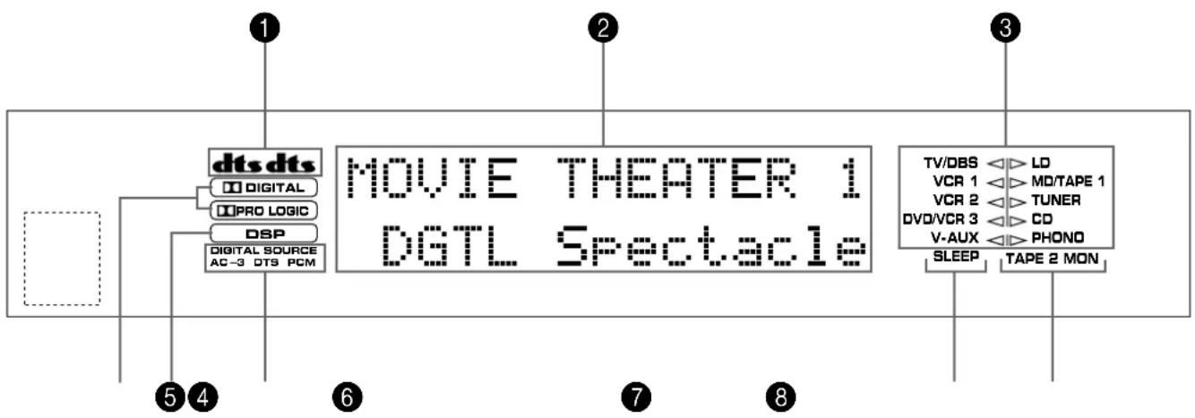
flowchart
graph TD
    A["dts dts"] --> B["Digital"]
    A --> C["PRO LOGIC"]
    A --> D["DSP"]
    A --> E["Digital Source AC-3 DTS PCM"]
    F["MOVIE THEATER 1 DGTL Spectacle"] --> G["TV/DBS"]
    F --> H["VCR 1"]
    F --> I["VCR 2"]
    F --> J["DV0/VCR 3"]
    F --> K["V-AUX"]
    F --> L["SLEEP"]
    F --> M["TAPE 2 MON"]
    N["1"] --> A
    O["2"] --> F
    P["3"] --> F
    Q["4"] --> A
    R["5"] --> A
    S["6"] --> A
    T["7"] --> F
    U["8"] --> F
① dt indicators
Keuzes: SW/MAIN/BOTH
10
line
| Frekwentie (Hz) | PEQ | HIGH | HIGH + PEQ (OVERALL) | | --------------- | ----- | ----- | --------------------- | | 20 | 0 | 0 | 0 | | 50 | 0 | 0 | 0 | | 100 | 0 | 0 | 0 | | 200 | 0 | 0 | 0 | | 500 | 0 | 0 | 0 | | 1k | 0 | 0 | 0 | | 2k | 0 | 0 | 0 | | 5k | 0 | 0 | 0 | | 10k | 0 | 0 | 0 | | 20k | 0 | 0 | 0 | | >20k | ~-3 | ~-4 | ~-6 |FRONT, REAR EFCT EQ
HIGH: FRQ 12,7 kHz
GAIN 0 dB
PEQ: FRQ 8,0 kHz
GAIN -3 dB
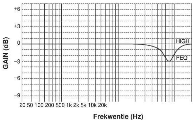
line
| Frekwentie (Hz) | GAIN (dB) | | --------------- | --------- | | 20 | 0 | | 50 | 0 | | 100 | 0 | | 200 | 0 | | 500 | 0 | | 1k | 0 | | 2k | 0 | | 5k | 0 | | 10k | 0 | | 20k | 0 | | High | 0 | | PEQ | -3 |line
| Frekwentie (Hz) | Gain (dB) | | --------------- | --------- | | 20 | 0 | | 50 | 0 | | 100 | 0 | | 200 | 0 | | 500 | 0 | | 1k | 0 | | 2k | 0 | | 5k | 0 | | 10k | 0 | | 20k | 0 | | 30k | -9 | | 40k | -6 | | 50k | -3 | | 60k | -1 | | 70k | 1 | | 80k | 3 | | 90k | 5 | | 100k | 6 | | 110k | 5 | | 120k | 3 | | 130k | 1 | | 140k | 0 | | 150k | 0 | | 160k | 0 | | 170k | 0 | | 180k | 0 | | 190k | 0 | | 200k | 0 |PEQ: FRQ ..... 1,0 kHz tot 12,7 kHz
GAIN +6 dB/-9 dB
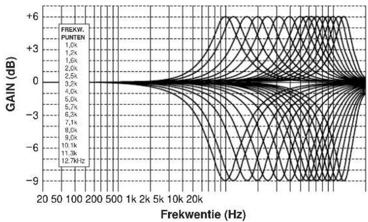
line
| Frekwertie (Hz) | GAIN (dB) | | --------------- | --------- | | 20 | +6 | | 50 | +3 | | 100 | +0 | | 200 | -3 | | 500 | -6 | | 1k | -9 | | 2k | -6 | | 5k | -3 | | 10k | 0 | | 20k | 3 | | 50k | 6 | | 100k | 9 | | 200k | 12.7 |2 Kies de bron die u wenst op te nemen.
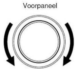
Afstandbediening
of
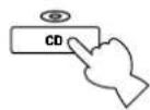
1 Kies de bron die u wilt opnemen.

CONCERT HALL 1 Hall A in Europe
→ Hall A in Europe EFCT TRIM ···· dB INIT. DLY ···· 30ms ROOM SIZE ···· 1.0 LIVENESS ···· ···· 5
Subprogramma
4
Standaard instelling is 1,0.
S. LIVENESS (surround live)
natural_image
Diagram showing a device with two circular components connected to a control panel (no text or symbols present)Reserve-geheugen
MAIN L/R....150W+150W
CENTER 150W
REAR L/R....150W+150W
FRONT L/R....45W+45W
SUBWOOFER (SPLIT L, R) (EFFECT OFF)
1,2V/1,2 kΩ
SUBWOOFER (MONO) (EFFECT OFF) ...... 2V/1,2 kΩ
Frekwentie 100 Hz/300 Hz/1 kHz/3 kHz/10 kHz
Versterking/afsluiting .... ±6 dB
Q 0,7
Lage Tonen Uitbreiding (MAIN L/R) ....+6 dB (70 Hz)
SUBWOOFER (fc = 90 Hz) 24 dB/oct.
CINEMA Equalizer
High-shelving filter Frekwentie .... 1,0 kHz tot 12,7 kHz Versterking/afsluiting .... -9 dB tot +6 dB
Parametrische equalizer Frekwentie .... 1,0 kHz tot 12,7 kHz Versterking/afsluiting .... -9 dB tot +6 dB Q .... 1,85
Audio-damping -20 dB


