USER MANUAL DSPAX1 YAMAHA
CAUTION: READ THIS BEFORE OPERATING YOUR UNIT.
- To assure the finest performance, please read this manual carefully. Keep it in a safe place for future reference.
- Install this unit in a cool, dry, clean place – away from windows, heat sources, sources of excessive vibration, dust, moisture and cold. Avoid sources of humming (transformers, motors). To prevent fire or electrical shock, do not expose the unit to rain or water.
- Never open the cabinet. If something drops into the set, contact your dealer.
- Do not use force on switches, controls or connection wires. When moving the unit, first disconnect the power plug and the wires connected to other equipment. Never pull the wires themselves.
- The openings on the cover assure proper ventilation of the unit. If these openings are obstructed, the temperature inside the unit will rise rapidly. Therefore, avoid placing objects against these openings, and install the unit in a well-ventilated area to prevent fire and damage.
(For Europe, UK, and China Models)
Be sure to allow a space of at least 10 cm behind, 10 cm on both sides and 30 cm above the top panel of the unit to prevent fire and damage.
- The voltage used must be the same as that specified on this unit. Using this unit with a higher voltage than specified is dangerous and may result in fire or other accidents.
YAMAHA will not be held responsible for any damage resulting from the use of this unit with a voltage other than that specified.
- Digital signals generated by this unit may interfere with other equipment such as tuners, receivers and TVs. Move this unit farther away from such equipment if interference is observed.
- Do not attempt to clean the unit with chemical solvents; this might damage the finish. Use a clean, dry cloth.
- Be sure to read the “Troubleshooting” section regarding common operating errors before concluding that the unit is faulty.
- When not planning to use this unit for a long period of time (e.g., a vacation), disconnect the AC power plug from the wall outlet.
- To prevent lightning damage, disconnect the AC power plug and disconnect the antenna cable when there is an electrical storm.
- Grounding or polarization - Precautions should be taken so that the grounding or polarization of the unit is not defeated.
- AC outlet
Do not connect audio equipment to the AC outlet on the rear panel if that equipment requires more power than the outlet is rated to provide.
This unit is not disconnected from the AC power source as long as it is connected to the wall outlet, even if this unit itself is turned off. This state is called the standby mode. In this state, this unit is designed to consume a very small quantity of power.
For U.K. customers
If the socket outlets in the home are not suitable for the plug supplied with this appliance, it should be cut off and an appropriate 3 pin plug fitted. For details, refer to the instructions described below.
Note: The plug severed from the mains lead must be destroyed, as a plug with bared flexible cord is hazardous if engaged in a live socket outlet.
Special Instructions for U.K. Model
IMPORTANT
THE WIRES IN MAINS LEAD ARE COLOURED IN ACCORDANCE WITH THE FOLLOWING CODE:
Blue: NEUTRAL
Brown: LIVE
As the colours of the wires in the mains lead of this apparatus may not correspond with the coloured markings identifying the terminals in your plug, proceed as follows:
The wire which is coloured BLUE must be connected to the terminal which is marked with the letter N or coloured BLACK. The wire which is coloured BROWN must be connected to the terminal which is marked with the letter L or coloured RED.
Making sure that neither core is connected to the earth terminal of the three pin plug.

DOLBY
DIGITAL
Manufactured under license from Dolby Laboratories. "Dolby", "AC-3", "Pro Logic", "Surround EX" and the double-D symbol are trademarks of Dolby Laboratories.
Confidential Unpublished Works. ©1992-1997 Dolby Laboratories, Inc. All rights reserved.

Manufactured under license from Digital Theater Systems, Inc. US Pat. No. 5,451,942 and other world-wide patents issued and pending. "DTS", "DTS Digital Surround" and "DTS ES" are trademarks of Digital Theater Systems, Inc. Copyright 1996 Digital Theater Systems, Inc. All Rights Reserved.
Contents
Introduction 2
Features 3
Getting Started 5
Controls and Functions 6
Preparations 12
Speaker System Configurations.... 13
Speaker Placement 14
Hookups 15
On-Screen Displays (OSD) 25
Speaker Settings 26
Speaker Output Levels 27
Basic Operation 30
Basic Playback 31
Basic Recording 35
Advanced Operation 36
SET MENU Items 37
Remote Control Features 50
Adjusting the Levels of the Effect Speakers 63
Setting the Sleep Timer....63
ZONE 2 64
Digital Sound Field Processing (DSP) 67
Hi-Fi DSP-Sound Field Program 68
CINEMA-DSP 69
CINEMA-DSP Sound Field Program 71
Sound Field Program Parameter Editing 73
Digital Sound Field Parameter Descriptions 74
Appendix 78
Troubleshooting 79
Reference Chart for the INPUT and OUTPUT Jacks 82
CINEMA - EQ Frequency Characteristics 82
Specifications 83
Introduction
Features 3
Introduction 3
Dolby Digital and Dolby Digital Surround EX 3
DTS and DTS ES 3
Comparing Surround Technologies .... 3
Digital Sound Fields (DSP) 4
Multi-function remote control.... 4
Various Input and Output Jacks 4
Built-in 8-channel power amplifier....4
Custom installation facility 4
Getting Started 5
Checking the Package Contents .... 5
Installing Batteries in the Remote Control 5
Using the Remote Control .... 5
Controls and Functions 6
Front Panel 6
Opening and Closing the Front Panel Door 7
Remote Control 8
Front Panel Display 10
Rear Panel 11
Introduction
Welcome to the exciting world of digital home entertainment. The DSP-AX1 is the most complete and advanced AV amplifier available. Though some of the more advanced features of this unit may not be familiar to you, they are easy to use. Incorporated state-of-the-art technology such as Dolby Digital and DTS can bring the same audio experience to your home as they have brought to feature films in quality theaters around the world. To make the listening experience even more enjoyable, the DSP-AX1 includes a number of exclusive, digitally created listening environments known as digital sound fields. Choosing a sound field program is like transporting yourself to such venues as an outdoor arena, an European church, or a cozy jazz club. Take some time now to read more about these features and enjoy the new experiences the DSP-AX1 brings to your home theater.
Dolby Digital and Dolby Digital Surround EX
The DSP-AX1 is equipped with a Dolby Digital decoder which reproduces industry standard Dolby Digital surround sound for a cinematic audio experience in your home. Dolby Digital is a 5.1 channel format because it uses five discrete channels (left and right Main channels, Center channel, and left and right Rear channels) and a special low frequency channel (that is used only enough to merit the "0.1" channel rating) to create incredibly realistic 360° surround effects. Recently, Dolby Digital Surround EX was introduced in movie theaters as an advanced surround technology. The addition of a Rear Center channel makes front-to-back transitions more realistic. You can enjoy the newest Dolby Digital Surround EX software with the CINEMA DSP programs in the DSP-AX1 such as Dolby Digital/Matrix 6.1.
DTS and DTS ES
The DSP-AX1 is also equipped with a DTS decoder, which uses a 5.1 channel system to create a full surround sound environment. It was developed as a way to replace the analog soundtracks of movies with six channels of digital sound. In comparison with Dolby Digital, DTS uses less compression to store the sound information. The newly presented DTS ES system reproduces digital sound similar to Dolby Digital Surround EX. The use of the Rear Center speaker along with the existing 5.1 channel speakers provides a fully immersive cinematic audio experience.
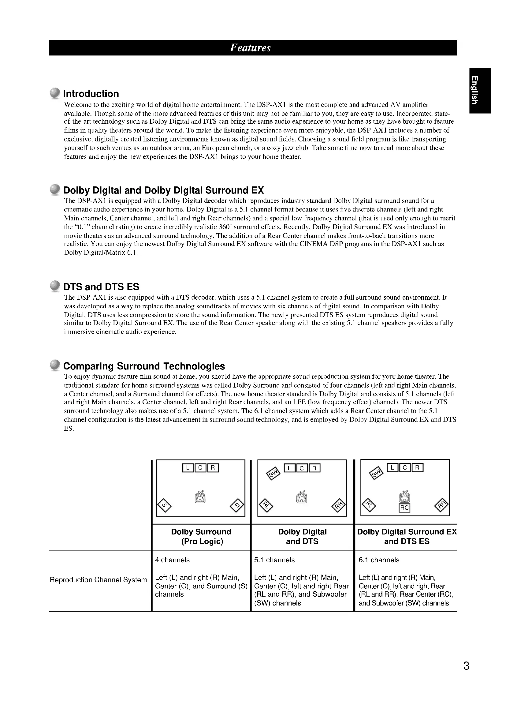
Comparing Surround Technologies
To enjoy dynamic feature film sound at home, you should have the appropriate sound reproduction system for your home theater. The traditional standard for home surround systems was called Dolby Surround and consisted of four channels (left and right Main channels, a Center channel, and a Surround channel for effects). The new home theater standard is Dolby Digital and consists of 5.1 channels (left and right Main channels, a Center channel, left and right Rear channels, and an LFE (low frequency effect) channel). The newer DTS surround technology also makes use of a 5.1 channel system. The 6.1 channel system which adds a Rear Center channel to the 5.1 channel configuration is the latest advancement in surround sound technology, and is employed by Dolby Digital Surround EX and DTS ES.
| 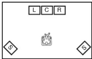 | 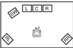 | 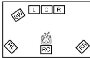 |
| Dolby Surround(Pro Logic) | Dolby Digitaland DTS | Dolby Digital Surround EXand DTS ES |
| Reproduction Channel System | 4 channelsLeft (L) and right (R) Main, Center (C), and Surround (S) channels | 5.1 channelsLeft (L) and right (R) Main, Center (C), left and right Rear (RL and RR), and Subwoofer (SW) channels | 6.1 channelsLeft (L) and right (R) Main, Center (C), left and right Rear (RL and RR), Rear Center (RC), and Subwoofer (SW) channels |
Digital Sound Fields (DSP)
Technological advances in sound reproduction over the last 30 years have enhanced the listening experience with improved clarity, precision, and power. However, something has been missing: the atmosphere and acoustic ambience of the public venue. Our Yamaha engineers have extensively researched the nature of sound acoustics and the way sound reflects inside a room. We sent these engineers to famous theaters and concert halls around the world to measure the acoustics of those venues with sophisticated microphones. The data they collected is used to recreate these environments in digital sound fields. Some of these digital sound fields have been created using data measured at the original venue; others have been created from combinations of data to form unique environments for specific purposes. Some have been designed especially for music, and others especially for movies. Of course, this only solves half of the problem. Because these engineers have no way of knowing the acoustics of your entertainment room, we have made it possible for you to adjust the various parameters of this data to tailor each virtual venue to your taste. You can use these sound fields to enhance any source and in combination with any of the following surround sound technologies.
CINEMA-DSP: Dolby Digital + DSP and DTS + DSP
The Dolby Digital system and DTS system show their full capability in large movie theaters, because feature film soundtracks are designed to be reproduced in such environments. It is difficult to recreate a sound environment similar to a movie theater in your entertainment room because of the room size, wall materials, and the number of speakers in your entertainment system. Yamaha DSP technology makes it possible for you to enjoy nearly the same sound experience as that of a large movie theater in your entertainment room by compensating for lack of presence and dynamics in your entertainment room with Yamaha's original digital sound fields combined with Dolby Digital or DTS soundtracks.
Virtual CINEMA DSP and HP CINEMA DSP
Yamaha developed the Virtual CINEMA DSP algorithm which allows you to experience the virtual sound fields without surround speakers. This makes it possible for the DSP-AX1 to produce a full surround sound catering to the number of speakers you have. The DSP-AX1 also has an HP (Headphones) CINEMA DSP algorithm which is achieved by the crosstalk processing applying the precise Head Related Transfer Function. You can therefore enjoy listening to the CINEMA DSP soundfields on headphones.
Multi-function remote control
The remote control can operate other audio-video components once you program the remote control using the manufacturer code and Learn feature.
The DSP-AX1 has various output jacks for audio and video signals as well as a digital recording output jack. Many input jacks are also available for connection to multiple audio-video sources. All the video inputs and outputs have S-video jacks in addition to standard composite video jacks for improved video picture quality. Component video input and output jacks are also available to deliver the excellent video signals from DVD players and other high quality video sources. The coaxial and optical digital signal jacks (provided for direct transmission of digital signals) automatically detect Dolby Digital, DTS, and PCM signals. A demodulator circuit is built into the Dolby Digital RF input so you can connect it directly to the Dolby Digital RF signal output on your LD player. Additionally, there are six audio inputs for discrete multichannel reproduction from an external decoder.
The DSP-AX1 also comes with a monaural subwoofer jack and split subwoofer jacks which can reproduce delicate but powerful low frequency effects.
Built-in 8-channel power amplifier
Main: 110 W + 110 W (8Ω) RMS Output Power, 0.015% THD, 20-20,000 Hz
Center: 110 W (8Ω) RMS Output Power, 0.015% THD, 20-20,000 Hz
Rear: 110 W + 110 W (8Ω) RMS Output Power, 0.015% THD, 20-20,000 Hz
Front: 35 W + 35 W (8Ω) RMS Output Power, 0.05% THD, 1 kHz
Rear Center: 110 W (8Ω) RMS Output Power, 0.015% THD, 20-20,000 Hz
Custom installation facility
You can make up a multi-room audio-video system with this unit. With this feature, you can set this unit to reproduce separate input sources in the main room and in a second (ZONE 2) room using the supplied remote control in the second room.
Checking the Package Contents
Check your package to make sure it has the following items.
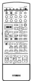
Remote Control

Alkaline Batteries (3) (LR6)
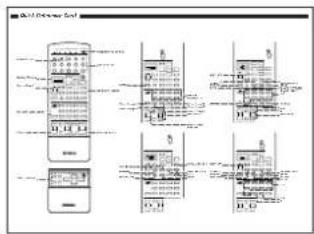
Quick Reference Guide
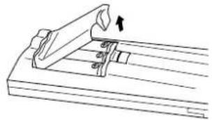
Installing Batteries in the Remote Control
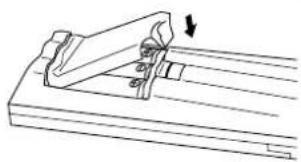
Insert the batteries in the correct direction by aligning the + and - marks on the batteries with the polarity illustrations (+ and -) inside the battery compartment.
Change the batteries periodically. Do not use old batteries together with new ones.
Do not use different types of batteries (such as alkaline and manganese batteries) together. Read the packaging carefully as these different types of batteries may have the same shape and color.
natural_image
Technical line drawing of a mechanical clamp or bracket assembly (no text or symbols)
natural_image
Technical line drawing of a mechanical clamp or bracket assembly with a downward arrow indicating force or motion (no text or symbols present)
■ About Changing Batteries
As the batteries wear out, the operating range of the remote control decreases and the TRANSMIT indicator does not flash or its light becomes dim. When you notice any of these conditions, change all of the batteries.
Notes:
- If the remote control is without batteries for more than 20 minutes, or if worn out batteries remain in the unit, the contents of the memory may be cleared.
If the memory is cleared, insert new batteries and reprogram any functions that may have been cleared.
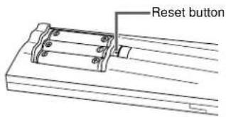
- After you insert new batteries, be sure to push RESET in the battery compartment using a ball point pen or similar object before using the remote control. (This does not clear the contents of the memory.)
Using the Remote Control
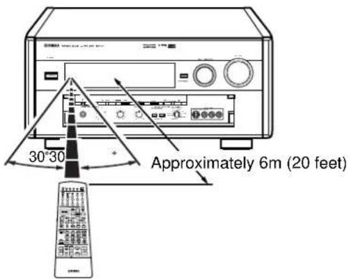
The remote control transmits a directional infrared beam. Be sure to aim the remote control directly at the remote control sensor on this unit during operation. When the sensor is covered or there is a large object between the remote control and the main unit, the sensor cannot receive signals. The sensor may not be able to receive signals properly when it is exposed to direct sunlight or a strong artificial light (such as a fluorescent or strobe light). In this case, change the direction of the light or reposition the main unit to avoid direct lighting.
■ About handling the remote control
Handle the remote control with care.
Do not spill water or other liquids on the remote control.
Do not drop the remote control.
Do not leave or store the remote control in the following types of conditions:
• high humidity or temperature such as near a heater, stove or bath; or
- dusty places; or
- in places subject to extremely low temperatures.
Front Panel
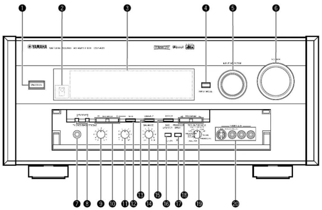
Turns this unit on (On mode) and off (Standby mode). When you turn on this unit, you will hear a click and there will be a four to five to second delay before this unit can reproduce sound.
In Standby mode, this unit consumes a small amount of power so it can respond to the remote control.
②Remote Control Sensor
Receives signals from the remote control.
③Front Panel Display
Shows information about the operational status of this unit (see page 10).
Selects the mode of input for sources that output two or more types of signals to this unit (see page 33).
You cannot control the input mode when you select 6CH INPUT as the input source.
Selects the input source (DVD, LD, D-TV, CBL/SAT, VCR 1, VCR 2, VCR 3, V-AUX, PHONO, CD, TUNER, TAPE, MD) you want to listen to or watch.
⑥VOLUME
Controls the output level of all audio channels. This does not affect the REC OUT level.
⑦PHONES
Outputs audio signals for private listening using headphones. When you connect headphones, no signals are output to the PREOUT jacks or the speakers.
⑧SPEAKERS A/B
When pushed in (ON), these buttons turn on the set of Main speakers connected to the A and/or B terminals on the rear panel.
⑨BASS
Adjusts the low frequency response for the left and right Main speaker channels.
Turn the control to the right to increase the low frequency response and turn the control to the left to decrease the low frequency response.
If you increase or decrease the low frequency sound to an extreme level, the tonal quality from the Center, Front Effect, Rear Center, and Rear speakers may not match that of the left and right Main speakers.
Adjusts the settings and parameter values of SET MENU items.
⑪TREBLE
Adjusts the high frequency response for the left and right main channels.
Turn the control to the right to increase the high frequency response and turn the control to the left to decrease the high frequency response.
If you increase or decrease the high frequency sound to an extreme level, the tonal quality from the Center, Front Effect, Rear Center, and Rear speakers may not match that of the left and right Main speakers.
⑫NEXT
Displays SET MENU items. This button works like ▽ on the remote control when using the SET MENU.
Switches between 6CH INPUT mode and normal input modes. 6CH INPUT mode takes priority over the source selected with INPUT SELECTOR.
You cannot use DSP sound field programs while using an external decoder.
14 BALANCE
Controls the balance of the sound levels coming from the right and left Main speaker(s). Setting this control to the center position “0” is appropriate for most situations.
15 EFFECT
Switches the effect speakers (Center, Front Effect, Rear and Rear Center) on and off. If you turn off the output of these speakers using EFFECT, all DTS and Dolby Digital audio signals are directed to the Main left and right channels except for the LFE channel.
When DTS or Dolby Digital signals are mixed, the left and right Main channel signal levels may not match.
⑯BASS EXTENSION ON/OFF
When pushed in (ON), this feature boosts the bass frequency of the left and right main channels by +6 dB (60 Hz) while maintaining overall tonal balance. This boost is useful if you do not use a subwoofer.
However, this boost may not be noticeable if the main speakers are set to “SMALL” and the bass output mode is set to “SW.”
⑰PROCESSOR DIRECT ON/OFF
When pushed in (ON), BASS, TREBLE, BALANCE, and BASS EXTENSION are bypassed, eliminating any alteration of the original signal.
18PROGRAM
Selects the sound field program (see page 34).
Selecting a sound field program turns on the effect.
19REC OUT/ZONE 2
Selects the source you want to direct to the audio/video recorder and ZONE 2 outputs independent of the source you are listening to in the main room. When set to the SOURCE/REMOTE position, the input source is directed to all outputs.
20VIDEO AUX
Inputs audio and video signals from a portable external source such as a video camera. To reproduce source signals from these jacks, select V-AUX as the input source. To direct this source to the VCR 1 output jacks, select VIDEO AUX using REC OUT/ZONE 2.
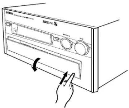
Opening and Closing the Front Panel Door
When you are not operating the controls behind the front panel door, close the door.
Remote Control
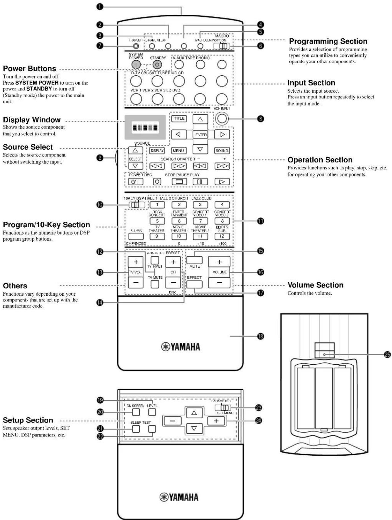
①Infrared window
Outputs infrared control signals. Aim this window at the component you want to operate.
②CLEAR
Used for clearing functions acquired using the Learn and Rename features, programmed macros, and preset manufacturer codes (see pages 61, 62).
③RE-NAME
Used for changing the source name in the display window (see page 61).
④LEARN
Used for setting up the manufacturer code or programming the functions of other remote controls (see pages 57, 58).
⑤MACRO
Used to program a series of operations onto a single button (see page 59).
⑥MACRO ON/OFF
Turns the macro function on and off.
⑦TRANSMIT
Flashes while the remote control is sending signals.
Switches to the 6CH INPUT mode when using an external decoder.
⑨LIGHT
Turns the light on or off.
When you press this button once, the light turns on for about ten seconds. Press again to turn off the light.
1010KEY/DSP
Selects the numeric button (10KEY) mode or DSP mode. You can use the 13 buttons to select numbers or DSP programs directly according to the position of this switch.
Select DSP programs or numbers according to the position of 10KEY/DSP. (Press a button repeatedly to select a DSP program within that group.)
⑫A/B/C/D/E
Selects one of the five preset station groups.
TV INPUT switches between TV and VCR mode.
TV MUTE mutes the TV sound.
⑬TV VOL +/-
Increases or decreases the TV volume level.
14+/-
PRESET +/- selects a preset station.
CH +/- selects the next or previous channel.
DISC +/- skips to the next or previous disc.
⑮MUTE
Mutes the sound. Press again to restore audio output at the previous volume level.
⑯VOLUME +/-
Increases or decreases the volume level.
⑰ EFFECT
Switches the effect speakers (center, front, rear, and rear center) on and off. If the output of these speakers is switched off, all DTS and Dolby Digital audio signals are directed to the main left and right channels except for the LFE channel.
18Cover
Slides down to show the setup buttons.
19LEVEL
Selects the effect speaker channels (center, front, rear and subwoofer) so you can adjust their level independently. Press this button repeatedly to select the effect speaker channel you want to adjust, then use + or - to adjust the level.
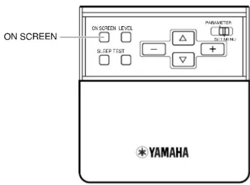
20 ON SCREEN
Selects the On-Screen Display mode for your video monitor.
②SLEEP Timer
Sets the Sleep Timer. Press repeatedly to set the amount of time before the main unit is automatically turned off.
22TEST
Selects the test mode (see page 27).
Selects the PARAMETER mode or SET MENU mode.
You can use the cursor / / + / - buttons to adjust DSP program parameter values or SET MENU items according to the position of this switch.
Selects and adjusts DSP program parameters and SET MENU items according to the position of PARAMETER/SET MENU.
25RESET
Press this button after you exchange batteries or when the remote control stops working properly. (Pressing RESET does not clear acquired functions.)
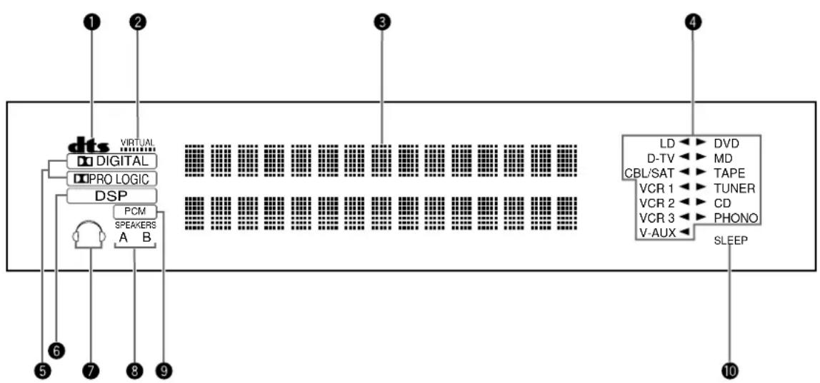
Front Panel Display
flowchart
graph TD
    A["dts"] --> B["Virtual Speakers"]
    B --> C["DSP"]
    C --> D["PCM Speakers"]
    D --> E["6"]
    A --> F["5"]
    A --> G["7"]
    A --> H["8"]
    A --> I["9"]
    A --> J["10"]

    K["Virtual Memory Units"] --> L["Memory Cells"]
    M["LD"] --> N["DVD"]
    O["D-TV"] --> P["MD"]
    Q["CBL/SAT"] --> R["TAPE"]
    S["VCR 1"] --> T["TUNER"]
    U["VCR 2"] --> V["CD"]
    W["VCR 3"] --> X["PHONO"]
    Y["V-AUX"] --> Z["SLEEP"]
①DTS indicator
Lights up when the built-in DTS decoder is on.
②VIRTUAL indicator
Lights up when using Virtual Cinema DSP (see page 34).
Shows the current DSP program and other information when adjusting or changing settings.
Shows the current input source with the arrow-shaped cursor.
⑤ DIGITAL and PRO LOGIC indicators
Lights up according to the type of Dolby signals this unit is reproducing.
“Digital” lights up when the built-in Dolby Digital decoder is on.
“DBRO LOGIC” lights up when the built-in Dolby Pro Logic Decoder is on.
⑥DSP indicator
Lights up when you select a digital sound field program.
⑦Headphones indicator
Lights up when headphones are connected.
⑧SPEAKERS A/B indicator
Lights up according to which set of main speakers are selected. Both indicators light up when both sets of speakers are selected.
9PCM indicator
Lights up when this unit is reproducing PCM (Pulse Code Modulation) digital audio signals.
⑩SLEEP indicator
Lights up while the Sleep Timer is on.
Rear Panel
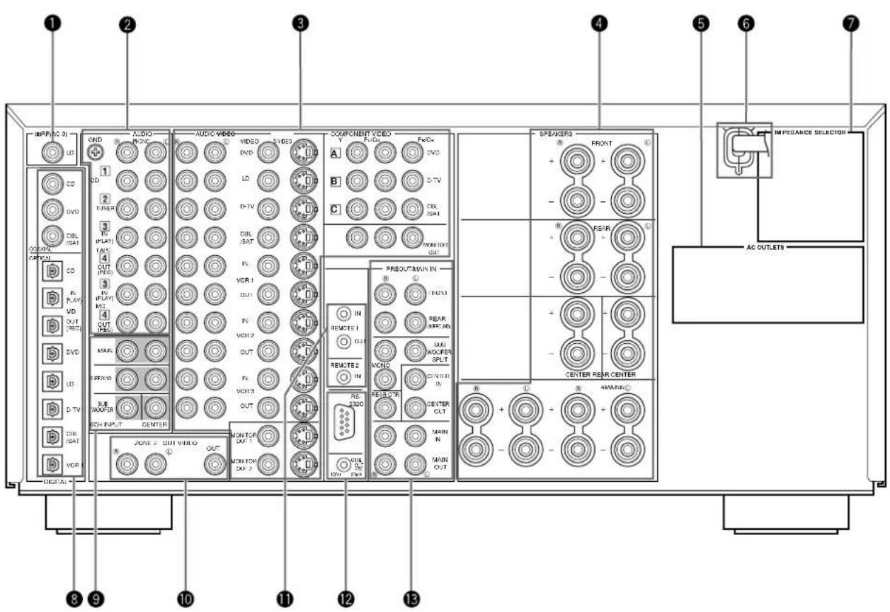
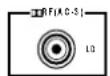
① RF (AC-3) input jack
Connect to the RF output terminal of your LD player.
②Audio equipment jacks
Refer to page 16 for hookup information.
③Video equipment jacks
Refer to page 18 for hookup information.
④Speaker terminals
Refer to page 20 for hookup information.
⑤AC OUTLETS
Use these outlets to supply power to your other audio/video equipment.
⑥AC power cord
Connect to a power outlet.
⑦IMPEDANCE SELECTOR
Use this switch to match the amplifier output to your speaker impedance. Turn off the power before you change the setting of this switch (see page 22).
⑧DIGITAL OPTICAL/COAXIAL jacks
Refer to page 15 for detailed information.
⑨6CH INPUT jacks
Refer to page 24 for hookup information.
⑩ZONE 2 OUT/VIDEO OUT jacks
Refer to page 64 for hookup information.
①REMOTE 1 IN/OUT/REMOTE 2 IN jacks
Refer to page 64 for hookup information.
⑫RS232C/CTRL OUT +5V terminals
These are control expansion terminals for commercial use. Consult your dealer for details.
⑬PRE OUT/MAIN IN jacks
Refer to page 23 for hookup information.
Preparations
Speaker System Configurations 13
Eight or Seven Speaker Configuration –Full Cinema DSP– 13
Six Speaker Configuration – Hi Fi DSP– 13
Five Speaker Configuration – Standard 5.1 Channel–.... 13
Four Speaker Configuration – Minimum Requirement– 13
Speaker Placement 14
Placing the Main Speakers .... 14
Placing the Center Speaker 14
Placing the Front Effect, Rear and Rear Center Speakers .... 14
When You Use a Projection Screen 14
Placing the Subwoofers.... 14
Hookups 15
Connecting to Digital Jacks 15
About the Video Jacks 15
About the ☐ RF (AC-3) Signal Input Jack 15
Connecting Audio Components 16
Connecting Video Components 18
Connecting Speakers....20
Connecting External Amplifiers 23
Connecting an External Decoder 24
Connecting Power Supply Cords 24
On-Screen Displays (OSD) 25
OSD Modes 25
Selecting the OSD Mode 25
Speaker Settings 26
Speaker Output Levels 27
Before You Begin 27
Dolby Surround Test 28
DSP Test 29
Speaker System Configurations
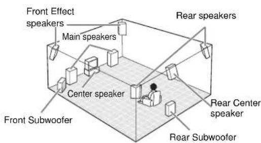
The most complete speaker configuration consists of eight speakers: the left and right Main speakers, a Center speaker, the left and right Rear speakers, the left and right Front Effect speakers, and a Rear Center speaker. If you do not use eight speakers, you can direct the signals for speakers that are not in your system to other speakers in your configuration. A Subwoofer can be used with any of these configurations to produce a fuller sound.
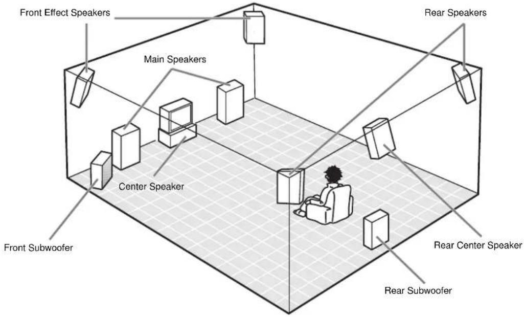
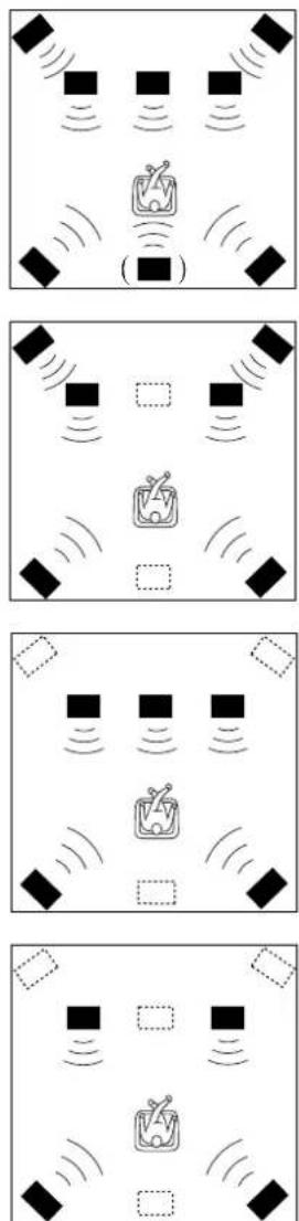
■ Eight or Seven Speaker Configuration –Full Cinema DSP–
When you reproduce feature film software, this configuration fully expresses the powerful and realistic sound qualities of 70 mm multitrack audio. The dialogue is positioned as if it were coming from directly on the screen, the sound effect is positioned slightly behind the screen, and the soundtrack music is positioned even further behind the screen to express the width and depth of the overall presentation. This configuration makes the most of this unit's capability.
The Rear Center speaker is useful for playback of Dolby Digital Surround EX or DTS ES.
■ Six Speaker Configuration – Hi Fi DSP–
This configuration is used the most for audio playback with HiFi DSP. It does not position the dialogue sound as well as a seven or eight speaker configuration. However, it creates a dynamic DSP (Digital Sound Field Processor) sound field which adds depth to the sound.
For this speaker configuration, change SET MENU item 1A. CENTER SP to "NONE" and 1D. REAR CT SP to "NONE" (see page 37).
■ Five Speaker Configuration –Standard 5.1 Channel–
This configuration does not express the height of the sound field as well as the seven or eight speaker configuration. However, it positions the dialogue sound as coming directly from the screen.
For this speaker configuration, change SET MENU item 1F. FRNT EFCT SP to "NONE" and 1D. REAR CT SP to "NONE" (see page 37).
■ Four Speaker Configuration – Minimum Requirement–
In this configuration, the Center speaker signals and Front Effect speaker signals are directed to the left and right Main speakers.
For this speaker configuration, change SET MENU item 1A. CENTER SP to "NONE," item 1F. FRNT EFCT SP to "NONE," and item 1D. REAR CT SP to "NONE" (see page 37).
Speaker Placement
Where you place your speakers has a tremendous effect on how well your system sounds.
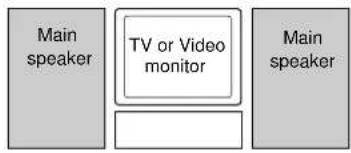
flowchart
graph TD
    A["Main speaker"] --> B["TV or Video monitor"]
    B --> C["Main speaker"]
■ Placing the Main Speakers
Place the left and right Main speakers an equal distance from the main listening position.
If you have a TV or video monitor in your system, the distance of each speaker from each side of the TV or video monitor should be the same.
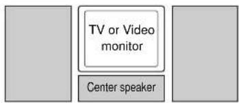
■ Placing the Center Speaker
If you have a TV or video monitor in your system, align the front face of the Center speaker with the front face of the monitor. Place the speaker as close to the monitor as possible, such as directly over or under the monitor. If you place the speaker under the monitor, the Front Effect speakers can adjust the height of the sound to correspond with the action on the screen (depending on the listener's position). If you have a projection screen in your system, place the Center speaker under the screen. Be sure to align the speaker with the center of the screen.
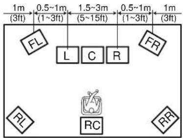
■ Placing the Front Effect, Rear and Rear Center Speakers
These speakers should be placed about 0.5\~1m (1\~3 feet) outside the Main speakers and in the front of the room. They should be turned toward the main listening position. Place the Rear speakers in the back of the room so they face the main listening position. The Rear speakers can be placed farther apart than the Front Effect speakers. The Front Effect and Rear speakers should be placed about 1.8m (6 feet) above the floor.
Once you begin listening to programs, continue to adjust the speaker placement until you obtain a balanced sound from the Main speakers and the Front Effect and Rear speakers.
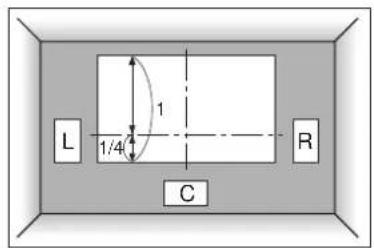
■ When You Use a Projection Screen
Place the speakers as shown in the illustration.
The Main speakers should be placed about one-quarter of the way up from the bottom of the screen.
Place the Center speaker in the center and directly under the screen. The Center speaker provides precise dialogue localization.
When you use a projection screen with your system, the Front Effect speakers provide better effect quality. The CINEMA-DSP sound field programs (see page 34) raise the sound from the Center speaker upward and provide natural sound corresponding with the video images.
■ Placing the Subwoofers
Place the Front Subwoofer near the Main speakers. Turn it slightly toward the center of the room to reduce wall reflections.
If you use a Rear Subwoofer, place it behind the main listening position. The placement of the Rear Subwoofer is not critical because of the ultralow frequencies of the sound being reproduced.
By adding a high quality Subwoofer to the speaker configurations shown on pages 21 and 22, you can enjoy more powerful and realistic movie effects, even if your Main speakers are large.
Note:
- If you use different brands of speakers (with different tonal qualities) in your configuration, the tone of a moving human voice and other types of sound may not shift smoothly. We recommend that you use speakers from the same manufacturer or speakers with the same tonal quality.
You can also adjust the output levels and equalization of your effect speakers using the SET MENU (see page 37).
If you are using small speakers, the addition of a Subwoofer will reinforce the sound effects of movies (see page 21).
Connecting to Digital Jacks
The DSP-AX1 has digital jacks for direct transmission of digital signals through either coaxial or fiber optic cables. You can use the digital jacks to input PCM, DTS and Dolby Digital bitstreams. When you connect components to both the COAXIAL and OPTICAL jacks (for CD, DVD, and CBL/SAT) priority is given to the input signals from the COAXIAL jack. All digital input jacks are acceptable for 96 kHz/24 bit digital signals.
■ About the Dust Protection Cap
Pull out the cap from the optical jack before you connect the fiber optic cable. Do not discard the cap. When you are not using the optical jack, be sure to put the cap back in place. This cap protects the jack from dust.
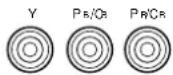
About the Video Jacks
There are three types of video jacks. Video signals input through the VIDEO jacks are the conventional composite video signals. Video signals input through the S VIDEO jacks are separated into luminance (Y) and color (C) video signals. The S-video signals achieve high quality color reproduction.
Video signals input through the COMPONENT VIDEO jacks are separated into luminance (Y) and color difference ( P_B/C_B , P_R/C_R ) video signals. The jacks are also separated into three for each signal. The description of the component video jacks may be different depending on the component (e.g. Y, C_B , C_R /Y, P_B , P_R /Y, B-Y, R-Y/etc.). Component video signals provide the best quality in picture reproduction.
Composite VIDEO terminal

S VIDEO terminal

COMPONENT VIDEO terminals
Note:
• Each type of video jack works independently. Signals input through the composite video, S-video, and component jacks are output through the corresponding composite video, S-video, and component jacks respectively.
Caution:
- Use a commercially available S-video cable when connecting to the S VIDEO jacks, and commercially available video cables when connecting to the COMPONENT VIDEO jacks.
- When you are using the COMPONENT VIDEO jacks, check the details in the owner's manual that came with the component being connected.
If your LD player has an ☐ RF (AC-3) signal output jack, connect it to the ☐ RF (AC-3) input jack on this unit. If ☐ RF (AC-3) and analog signals are input at the same time, priority is given to the RF signals. When you want to reproduce ☐ RF (AC-3) signals, set the input mode to "D.D. RF" using INPUT MODE.
Note:
- RB (AC-3) signals cannot be output using the REC OUT selector. When you record sound or images from an LD player, be sure to connect the player to either the DIGITAL OPTICAL or analog AUDIO jacks.
Caution:
- Even if you connect an LD player with an FF (AC-3) output jack to this unit, you cannot reproduce Dolby Digital sound from all LD discs. You must playback an LD disc encoded with Dolby Digital signals in order to take advantage of the Dolby Digital sound.
Connecting Audio Components
Before you connect any components, disconnect the power supply to all the components you plan to connect including the DSP-AX1 and determine which jacks are for the left and right channels and for input and output.
When you connect other YAMAHA audio equipment (such as a CD player or changer, Tuner, MD deck, or tape deck), connect to terminals with the same number labels. Yamaha applies this labelling system to all its products.
In the hookup illustrations on the following pages:
indicates signal direction,
indicates coaxial cables,
indicates left side analog cables,
— indicates right side analog cables,
indicates optical cables; and,
indicates S-video cables.
After you finish all hookups, check them again to make sure they are correct.
flowchart
graph TD
    A["AM/FM Tuner"] -->|CD| B["Audio Output"]
    A -->|EP| B
    B --> C["Output"]
    style A fill:#f9f,stroke:#333
    style B fill:#ccf,stroke:#333
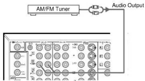
■ Connecting an AM/FM Tuner
1 Connect the left and right signal output jacks on your tuner to the TUNER 2 L and R jacks.
flowchart
graph TD
    A["Turntable"] --> B["Output"]
    B --> C["Ground"]
    C --> D["Switch"]
    D --> E["Output"]
    style A fill:#f9f,stroke:#333
    style E fill:#bbf,stroke:#333
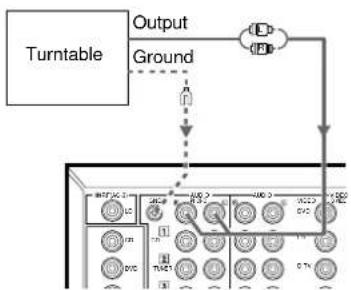
■ Connecting a Turntable
1 Connect the left and right signal output cords to the PHONO Ⓛ and Ⓡ jacks.
Note:
• These jacks are for connecting a turntable with an MM or high output MC cartridge. If you have a turntable with a low output MC cartridge, use an inline boosting transformer or MC-head amplifier when connecting to these jacks.
Caution:
- The GND terminal does not electrically ground the turntable. It simply reduces noise in the signal. In some cases, you may hear less noise if you do not connect to the GND terminal.
flowchart
graph TD
    A["Optical Output"] --> B["CD Player"]
    C["Coaxial Output"] --> B
    B --> D["Analog Output"]
    D --> E["Feedback to CD Player"]
    E --> F["Output"]
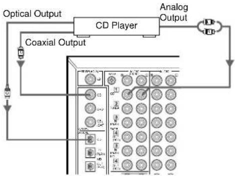
■ Connecting a CD Player
1 Connect the left and right analog signal output jacks on your CD player to the CD 1 L and ® jacks.
Notes:
- The COAXIAL CD and OPTICAL CD jacks are available for a CD player which has coaxial or optical digital outputs.
- When you connect a CD player to both the COAXIAL CD and OPTICAL CD jacks, priority is given to the input signals from the COAXIAL CD jack.
- The OPTICAL jacks on this unit conform to the EIA standard. If you use a fiber optic cable that does not conform to this standard, the DSP-AX1 may not function properly.
Hookups
flowchart
graph TD
    A["Input"] --> B["Tape Deck"]
    B --> C["Analog Input"]
    B --> D["Analog Output"]
    B --> E["Output"]
    E --> F["Feedback to Tape Deck"]
    F --> G["Component Layout"]
    G --> H["Control Signals"]
    style A fill:#f9f,stroke:#333
    style B fill:#ccf,stroke:#333
    style C fill:#cfc,stroke:#333
    style D fill:#fcc,stroke:#333
    style E fill:#ffc,stroke:#333
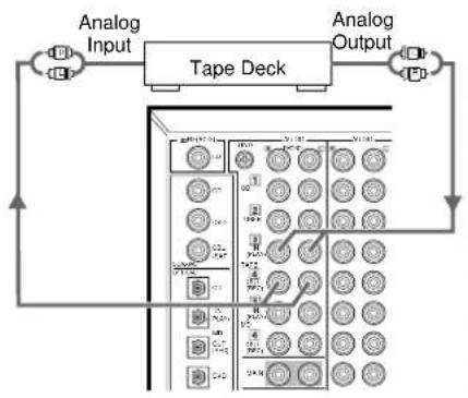
■ Connecting a Tape Deck
1 Connect the left and right signal output jacks on your tape deck to the TAPE 3 (PLAY) ① and ⑧ jacks.
2 Connect the left and right signal input jacks on your tape deck to the TAPE 4 (REC) Ⓛ and ® jacks.
Notes:
- You can monitor audio recordings if you connect a three-head tape deck to the TAPE [3] (PLAY) jacks.
- When you connect a tape deck to the DSP-AX1, keep the deck's power on while using the DSP-AX1. If the power is off, the DSP-AX1 may distort the sound from other equipment.
- When you record from source equipment connected to the DSP-AX1 while the DSP-AX1's power is off, the recorded sound may be distorted. To avoid this problem, turn on the DSP-AX1.
flowchart
graph TD
    A["Optical Input"] --> B["MD or DAT Deck"]
    B --> C["Analog Input"]
    B --> D["Analog Output"]
    D --> E["Output"]
    style A fill:#f9f,stroke:#333
    style B fill:#ccf,stroke:#333
    style C fill:#cfc,stroke:#333
    style D fill:#fcc,stroke:#333
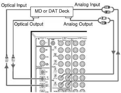
■ Connecting an MD or DAT Deck
1 Connect the left and right analog signal output jacks on your MD or DAT deck to the MD 3 (PLAY) Ⓛ and Ⓡ jacks.
② Connect the left and right analog signal input jacks on your MD or DAT deck to the MD 4 (REC) ① and ⑧ jacks.
3 Connect the optical digital signal output jack on your MD or DAT deck to the OPTICAL MD (PLAY) jack.
4 Connect the optical digital signal input jack on your MD or DAT deck to the OPTICAL MD (REC) jack.
Note:
- When you connect your MD or DAT deck to both the analog and digital input and output jacks, priority is given to the digital signals.
Connecting Video Components
Before you connect any components, disconnect the power supply to all the components you plan to connect including the DSP-AX1 and determine which jacks are for the left and right channels and for input and output. After you finish all hookups, check them again to make sure they are correct.
Note:
- If you make S-video connections to this unit, it is not necessary to make composite video connections. If both types of connections are made, this unit gives priority to the S-video signal.
flowchart
graph TD
    A["Optical Output"] --> B["LD Player"]
    C["RF-Signal Output"] --> B
    D["S-video Output"] --> B
    E["Video Output"] --> B
    B --> F["Analog Audio Output"]
    B --> G["RF-Signal Output"]
    style A fill:#f9f,stroke:#333
    style C fill:#f9f,stroke:#333
    style D fill:#f9f,stroke:#333
    style E fill:#f9f,stroke:#333
    style B fill:#ccf,stroke:#333
    style F fill:#ccf,stroke:#333
    style G fill:#ccf,stroke:#333
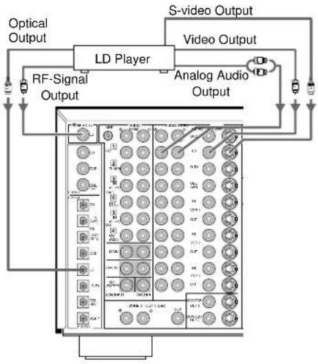
■ Connecting an LD Player
1 Connect the left and right audio signal output jacks on your LD player to the LD ① and ⑧ jacks.
If your LD player has an RF signal or optical digital signal outputs, you can connect them to this unit.
Connect the RF signal output jack on your LD player to the ☐☐ RF (AC-3) LD jack.
Connect the optical digital signal output jack on your LD player to the OPTICAL LD jack.
2 Connect the composite video signal output jack on your LD player to the LD VIDEO jack.
If your LD player has an S-video output, you can connect it to this unit. Connect the S-video signal output jack on your LD player to the LD S VIDEO jack.
flowchart
graph TD
    A["Optical Output"] --> B["Digital TV/TV"]
    B --> C["Analog Audio Output"]
    B --> D["Video Output"]
    D --> E["Component Output"]
    E --> F["S-video Output"]
    E --> G["Video Output"]
    G --> H["Analog Audio Output"]
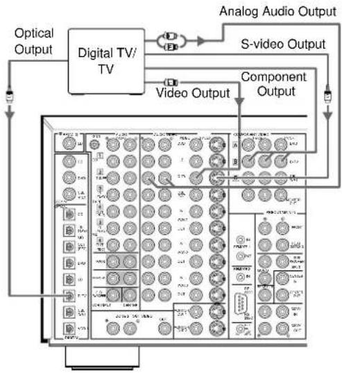
■ Connecting a TV or Digital TV
1 Connect the left and right analog signal output jacks on your TV to the D-TV Ⓐ and Ⓡ jacks.
If your TV has an optical digital signal output, you can connect it to this unit.
Connect the optical digital signal output jack on your TV to the OPTICAL D-TV jack.
2 Connect the composite video signal output jack on your TV to the D-TV VIDEO jack.
If your TV has an S-video output or component video output, you can connect it to this unit.
Connect the S-video signal output jack on your TV to the D-TV S VIDEO jack or connect the component signal output jacks on your TV to the D-TV COMPONENT VIDEO jacks.
flowchart
graph TD
    A["Optical Output"] --> B["Satellite/Cable TV Tuner"]
    C["Coaxial Output"] --> B
    D["Video Output"] --> B
    E["Component Output"] --> B
    F["Analog Audio Output"] --> B
    G["S-video Output"] --> B
    H["Video Output"] --> B
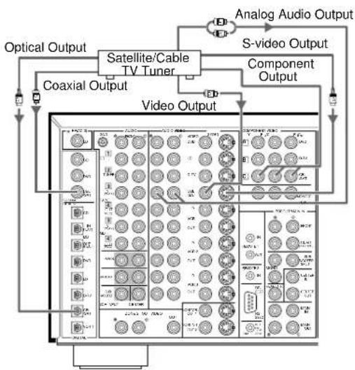
■ Connecting a Satellite Tuner or Cable TV Tuner (Set Top Box)
1 Connect the left and right audio signal output jacks on your tuner to the CBL/SAT ① and ⑧ jacks.
If your tuner has coaxial or optical digital signal outputs, you can connect them to this unit.
Connect the coaxial digital signal output jack on your tuner to the COAXIAL CBL/SAT jack.
Connect the optical digital signal output jack on your tuner to the OPTICAL CBL/SAT jack.
2 Connect the composite video signal output jack on your tuner to the CBL/SAT VIDEO jack.
If your tuner has an S-video or component video output, you can connect it to this unit. Connect the S-video signal output jack on your tuner to the CBL/SAT S VIDEO jack or connect the component signal output jacks on your tuner to the CBL/SAT COMPONENT VIDEO jacks.
Hookups

flowchart
graph TD
    A["Audio Input"] --> B["VCR"]
    C["Audio Output"] --> B
    D["Video Input"] --> B
    E["S-video Input"] --> B
    F["S-video Output"] --> B
    G["Video Output"] --> B
    B --> H["Control Panel"]
    style B fill:#f9f,stroke:#333,stroke-width:2px
flowchart
graph TD
    A["Optical Output"] --> B["DVD player"]
    C["Coaxial Output"] --> B
    D["Analog Audio Output"] --> B
    E["S-video Output"] --> B
    F["Component Output"] --> B
    G["Video Output"] --> B
    B --> H["Grid of 12 panels with labels like 'C', 'D', 'E', etc."]
■ Connecting a VCR
1 Connect the left and right audio signal output jacks on your VCR to the VCR 1 IN Ⓛ and Ⓡ jacks.
2 Connect the left and right audio signal input jacks on your VCR to the VCR 1 OUT Ⓛ and Ⓡ jacks.
3 Connect the composite video signal output jack on your VCR to the VCR 1 VIDEO IN jack.
If your VCR has an S-video output, you can connect it to this unit. Connect the S-video signal output jack on your VCR to the VCR 1 IN S VIDEO jack.
4 Connect the composite video signal input jack on your VCR to the VCR 1 VIDEO OUT jack.
If your VCR has an S-video input, you can connect it to this unit. Connect the S-video signal input jack on your VCR to the VCR 1 OUT S VIDEO jack.
Notes:
- You can connect other VCRs to the DSP-AX1 using the VCR 2 and VCR 3 jacks.
- If your VCR has an optical digital signal output jack, connect it to the OPTICAL VCR 1 jack of this unit.
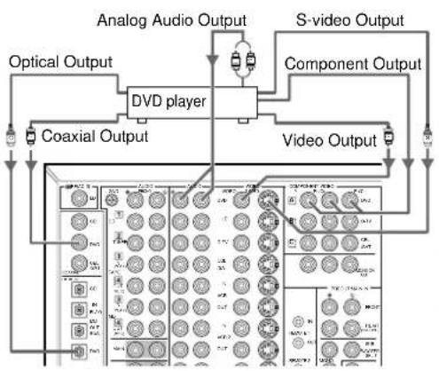
■ Connecting a DVD Player
1 Connect the left and right analog signal output jacks on your DVD player to the DVD Ⓛ and ® jacks.
If your DVD player has coaxial or optical digital outputs, you can connect one or both of them to this unit.
Connect the coaxial digital signal output jack on your DVD player to the COAXIAL DVD jack.
Connect the optical digital signal output jack on your DVD player to the OPTICAL DVD jack.
2 Connect the composite video signal output jack on your DVD player to the DVD VIDEO jack.
If your DVD player has an S-video output or component video output, you can connect it to this unit. Connect the S-video signal output jack on your DVD player to the DVD S-VIDEO jack or connect the component signal output jacks on your DVD player to the DVD COMPONENT VIDEO jacks.
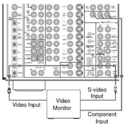
■ Connecting a Video Monitor
1 Connect the composite video signal input jack on your monitor to MONITOR OUT 1 VIDEO jack.
If your video monitor has an S-video input, you can connect it to this unit. Connect the S-video signal input jack on your video monitor to the MONITOR OUT 1 S-VIDEO jack.
If your video monitor has component video signal inputs, you can connect them to the COMPONENT VIDEO MONITOR OUT jacks.
Note:
- You can connect another monitor to this unit using the MONITOR OUT 2 jacks.
Connecting Speakers
This section explains how to connect speakers to the DSP-AX1. After you finish connecting your speakers, use the SET MENU to change the signal output settings according to the number and size of the speakers in your configuration.
natural_image
Diagram of a cable being inserted into three cylindrical components (no text or symbols)
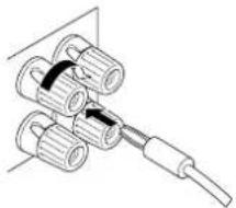
BANANA PLUG
natural_image
Diagram of a mechanical assembly with multiple cylindrical components and a connecting rod (no text or symbols)
[Except for Europe and UK models]
flowchart
graph TD
    A["Right Main Speaker A"] --> C["Speaker Output"]
    B["Left Main Speaker A"] --> C
    C --> D["Speaker Output"]
    E["Right Main Speaker B"] --> F["Speaker Output"]
    G["Left Main Speaker B"] --> F
    F --> H["Speaker Output"]
    I["Speaker Output"] --> J["Speaker Output"]
    K["Speaker Output"] --> L["Speaker Output"]
Center Speaker
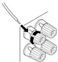
■ Using Speaker Cords
A speaker cord is actually a pair of insulated cables running side by side. One of the cables is colored or shaped differently, perhaps with a stripe, groove or ridge. To make sure you always connect speakers with the correct polarity, determine the difference between the cables of your speaker cord, make a note of which cable you plan to use for which polarity (+ and -), and always connect the speaker cords consistently.
1 Strip off 9 mm (3/8 in.) of insulation from the ends of the cables.
2 Twist the exposed wires of the cable together to prevent short circuits.
3 Loosen the terminal knob by turning it counterclockwise.
4 Insert only the exposed portion of the cable into the slot in the side of the terminal, and tighten the terminal knob.
Note:
- If your speaker cords have banana plugs, tighten the terminal knob and insert the plug into the end of the terminal. (Except for Europe and UK Models)
Caution:
- Connect the speaker cords with care to avoid creating a short circuit. If you turn on the power and there is a short circuit, this unit may be damaged even though the protection circuit automatically shuts off the power.
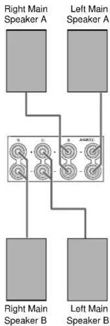
■ Connecting the Main Speakers
Before connecting any speaker cords, identify which terminals are for the right and left channels and also the + and - polarities. If you connect speakers with the wrong polarity (+ to -), the DSP-AX1 will not reproduce clear sound.

Connect the + and - terminals of your right and left Main speakers to the Ⓛ and Ⓡ MAIN + and - terminals on this unit.
■ Connecting the Center Speaker

Connect the + terminal of your Center speaker to the CENTER + terminal and the - terminal of your Center speaker to the CENTER - terminal.
Hookups
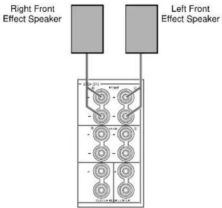
■ Connecting the Front Effect Speakers
Connect the + and - terminals of your right and left Front Effect speakers to the Ⓐ and Ⓡ FRONT + and - terminals on this unit.
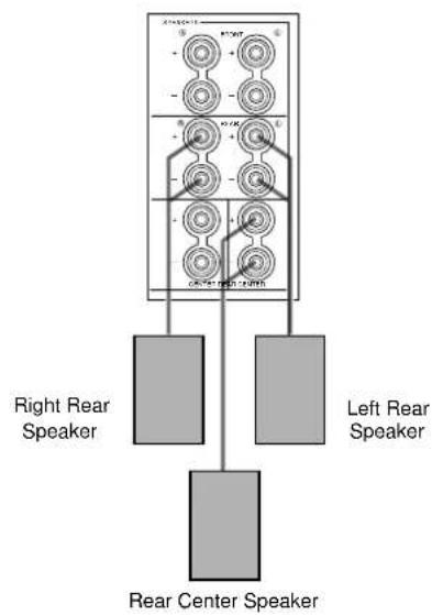
■ Connecting the Rear and Rear Center Speakers
1 Connect the + and - terminals of your right and left Rear speakers to the Ⓗ and ® REAR + and - terminals on this unit.
2 Connect the + terminal of your Rear Center speaker to the REAR CENTER + terminal and the - terminal of your Rear Center speaker to REAR CENTER - terminal.
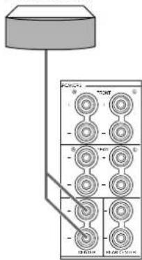
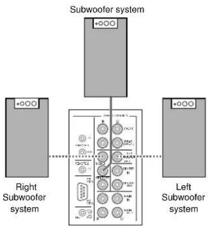
■ Connecting a Front Subwoofer
Connect the signal input jack on your subwoofer to the PRE OUT/MAIN IN SUBWOOFER MONO jack.
By connecting two Subwoofers to the SUBWOOFER SPLIT jacks, this unit can reproduce subtle directional changes in the low frequency sounds. When you use two Subwoofers, connect both of them to the SUBWOOFER SPLIT jacks using pin plugs.
Caution:
- The SUBWOOFER jacks (output) have a built-in high cut-off filter (90 Hz). When using a powered subwoofer, set the high cut-off frequency to "MAX" on your Subwoofer.
flowchart
graph TD
    A["Right Subwoofer system"] --> B["Subwoofer system"]
    B --> C["Left Subwoofer system"]
    style A fill:#f9f,stroke:#333
    style B fill:#ccf,stroke:#333
    style C fill:#cfc,stroke:#333
flowchart
graph TD
    A["Right Rear Speaker"] --> C["Subwoofer system"]
    B["Left Rear Speaker"] --> C
    C --> D["Device with ports labeled '1', '2', '3', '4', '5', '6' and connection points marked '+0-0-0'"]
    style C fill:#f9f,stroke:#333
    style D fill:#ccf,stroke:#333
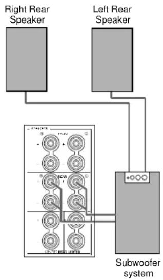
■ Connecting a Rear Subwoofer
By using both Front and Rear Subwoofers, the CINEMA-DSP sound field programs can produce realistic movie effects with powerful, dynamic sound. To take advantage of this dynamic sound, be sure to set the 1C. REAR L/R SP item in the SET MENU to “LARGE” (see page 37), and connect your Rear speakers and Subwoofer as shown below.
1 Connect the right + input terminal on your Subwoofer to the REAR Ⓡ + terminal, and the right - input terminal on your Subwoofer to the REAR Ⓡ - terminal with speaker cords.
2 Connect the left + input terminal on your Subwoofer to the REAR Ⓛ + terminal, and the left - input terminal on your Subwoofer to the REAR Ⓛ - terminal with speaker cords.
3 Connect your Rear speakers to the output terminals on the Rear Subwoofer.
Be sure to connect the Rear speakers to the Subwoofer with the correct polarity.
Note:
- Adjust the speaker volume for the Subwoofer with the controls on the Subwoofers, not on the DSP-AX1.
WARNING
Do not change the IMPEDANCE SELECTOR switch setting while the power to this unit is on, otherwise this unit may be damaged.
IF THIS UNIT FAILS TO TURN ON WHEN THE STANDBY/ON SWITCH IS PRESSED:
The IMPEDANCE SELECTOR switch may not be set to either end. If so, set the switch to either end when this unit is in the standby mode.

■ Impedance Selector switch
Select the position whose requirements your speaker system meets.

(Upper position)
Front Effect:
The impedance of each speaker must be 6Ω or higher.
Rear: The impedance of each speaker must be 4Ω or higher.
Rear Center:
The impedance of the speaker must be 4Ω or higher.
Center: The impedance of the speaker must be 4 or higher.
Main: If you use one pair of main speakers, the impedance of each speaker must be 4 or higher.
If you use two pairs of main speakers, the impedance of each speaker must be 8 or higher.

(Lower position)
Front Effect:
The impedance of each speaker must be 8Ω or higher.
Rear: The impedance of each speaker must be 8 or higher.
Rear Center:
The impedance of the speaker must be 8 or higher.
Center: The impedance of the speaker must be 8 or higher.
Main: If you use one pair of main speakers, the impedance of each speaker must be 8 or higher.
If you use two pairs of main speakers, the impedance of each speaker must be 16 or higher.
Connecting External Amplifiers
If you want to increase the power output to the speakers, or want to use another amplifier, connect an external amplifier to the PRE OUT/MAIN IN terminals as follows.
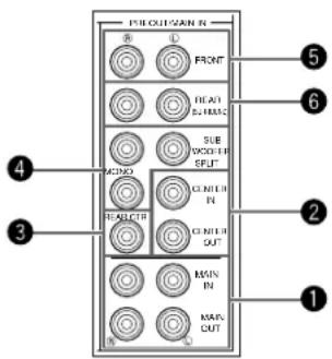
①MAIN jacks
MAIN OUT jacks ..... Main channel line output jacks.
The signals output through these jacks are affected by BASS, TREBLE, BALANCE, and BASS EXTENSION settings.
MAIN IN jacks ...... Line input to the DSP-AX1 Main channel amplifiers.
②CENTER jacks
CENTER OUT jack . Center channel line output jacks.
CENTER IN jack ..... Line input to the DSP-AX1 Center channel amplifier.
③REAR CT jack
Rear Center channel line output jack.
④SUBWOOFER jacks
Subwoofers reinforce very low frequencies.
MONO .... Main, Center and Rear channel frequencies below 90 Hz are output through this jack. You can also direct DTS and Dolby Digital LFE signals to this output.
SPLIT ...... The SPLIT jacks output stereo separation for the Main and Rear channels and a split mono signal for the Center and LFE channels.
Adjust the volume level of the subwoofer with the control on the subwoofer. Subwoofer volume cannot be adjusted from this unit. Depending on the settings in SET MENU items 1. SPEAKER SET, 3A. LFE LEVEL and 4A. LFE LEVEL, some signals may not be output from the SUBWOOFER jacks.
⑤FRONT
Front Effect channel line output jacks.
⑥ REAR (SURROUND)
Rear channel line output jacks.
Note:
- When RCA pin plugs are connected to the PRE OUT/MAIN IN output jacks for output to external amplifiers, the corresponding internal amplifiers will be muted.
Connecting an External Decoder
The DSP-AX1 is equipped with six additional input jacks (left and right MAIN, CENTER, left and right SURROUND and SUBWOOFER) for discrete multi-channel input from an external decoder, sound processor, or pre-amplifier.
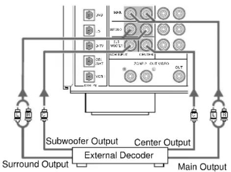
flowchart
graph TD
    A["Main Output"] --> B["External Decoder"]
    B --> C["Subwoofer Output"]
    B --> D["Center Output"]
    B --> E["Surround Output"]
    C --> F["Control Panel"]
    D --> F
    E --> F
    F --> G["Output"]
    style A fill:#f9f,stroke:#333
    style B fill:#ccf,stroke:#333
    style C fill:#cfc,stroke:#333
    style D fill:#fcc,stroke:#333
    style E fill:#cff,stroke:#333

Connect the output jacks on your external decoder to the 6CH INPUT jacks.
Be sure to match the left and right outputs to the left and right input jacks for the main and surround channels.
To listen to the sound from your external decoder, press 6CH INPUT on this unit or the remote control.
Note:
- When you select 6CH INPUT as the input source, this unit automatically turns off the digital sound field processor, and you cannot listen to DSP programs.
Connecting Power Supply Cords
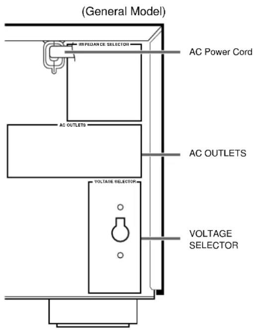
■ Connecting the AC Power Cord
After completing all connections, plug the AC power cord into a convenient AC outlet.
■ AC OUTLETS
Use these to connect the power cords from your other components to this unit. The power to the switched outlets is controlled by this unit's STANDBY/ON (SYSTEM POWER ON or STANDBY on the remote). These outlets will supply power to any connected unit whenever this unit is turned on. The maximum power (total power consumption of components) that can be connected to AC OUTLETS is 100W.
■ VOLTAGE SELECTOR (General and China Models)
The voltage selector on the rear panel of this unit must be set for your local voltage before plugging into the AC main supply.
Voltages are 110/120/220/240 V AC, 50/60 Hz.
You can display the operation information for this unit on a video monitor. If you display the SET MENU and DSP sound field program parameter settings on a screen, it is much easier to see the available options and parameters than it is by reading this information on the front panel display.
If a video source is being reproduced, the OSD is superimposed over the image.
If a video source is not being reproduced (or the power of the source equipment is off), the OSD is shown on a blue background.
OSD Modes
You can change the amount of information the OSD shows.
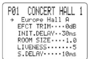
Full Display
Full Display .... This mode always shows the sound field program parameter settings on the video monitor (see page 73).
Short Display .... This mode briefly shows the same contents as the front panel display at the bottom of the screen, then disappears.
Display Off .... This mode briefly shows the "DISPLAY OFF" message at the bottom of the screen, then disappears. Afterwards, no changes to operations appear on the screen except those of the ON SCREEN.
Notes:
- When you choose the Full Display mode, INPUT SELECTOR, VOLUME and some other types of operation information are displayed at the bottom of the screen in the same format as the front panel display.
- The OSD signal is not output through the REC OUT Selector, and will not be recorded with any video signal.
- The SET MENU, TEST DOLBY SUR and TEST DSP appear regardless of the OSD mode.
P01 CONCERT HALL 1
Europe Hall A
Short Display
Selecting the OSD Mode
When you turn on the power, the video monitor and front panel display shows the level of the main volume for a few seconds and then switches to show the current sound field program.
2 Press ON SCREEN on the remote control repeatedly to change the display mode.
The OSD mode changes in the following order: Full Display, Short Display, and Display Off.
Caution:
- If you choose a video input source that has equipment connected to both the S VIDEO IN and composite VIDEO IN jacks, and both the S VIDEO OUT and composite VIDEO OUT jacks are connected to a video monitor, the video signal is output to both the S VIDEO OUT and VIDEO OUT jacks. However, the OSD is carried only on the S-video signal. If no video signal is input, the OSD is carried on both the S-video and composite video signals.
- If your video monitor is connected only to the COMPONENT VIDEO terminals of this unit, the OSD is not shown. Make sure to connect your video monitor to the COMPONENT VIDEO terminal and either VIDEO or S VIDEO terminals if you would like to see the OSD.
- Playing back video software that has an anti-copy signal or video signals with a lot of noise may produce unstable images.
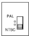
■ PAL/NTSC Switch (For General and China Models)
This unit is designed for use with both the NTSC and PAL television formats. Set this switch to the position compatible with your TV.
Speaker Settings
The DSP-AX1 has seven SPEAKER SET items in the SET MENU that you must set according to the number of speakers in your configuration and their size. The following table summarizes these SPEAKER SET items, and shows the initial settings as well as other possible settings.
If the initial settings are not appropriate for your speaker configuration, change the settings in the SET MENU (see page 37).
Summary of SPEAKER SET items 1A through 1G
| Item | | Initial SettingDescription |
| 1A. CENTER SP | Selects the Center channel output mode according to the size of the Center speaker.The possible settings are LRG (large), SML (small) and NONE. | LRG |
| 1B. MAIN SP | Selects the Main channel output mode according to the size of the Main speakers.The possible settings are LARGE and SMALL. | LARGE |
| 1C. REAR L/R SP | Selects the Rear channel output mode according to the size of the Rear speakers.The possible settings are LRG (large), SML (small) and NONE. | LRG |
| 1D. REAR CT SP | Selects the Rear center channel output according to the size of the Rear Center speaker.The possible settings are LRG (large), SML (small) and NONE. | LRG |
| 1E. LFE/BASS OUT | Selects a speaker for the LFE/Bass signal output.The possible settings are SW (subwoofer), MAIN, and BOTH. | BOTH |
| 1F. FRNT EFCT SP | Selects the Front Effect signal output mode for the Front Effect signals.The possible settings are YES and NONE. | YES |
| 1G. MAIN LEVEL | Selects the output level for the Main channel signal.The possible settings are Normal and -10 dB. | Normal |
Speaker Output Levels
This section explains how to set the speaker output levels using the test tone generator. The Dolby Surround test is for balancing the output levels of the six speakers required for surround sound systems. The DSP test is for balancing the Front Effect speakers with the Main speakers for the DSP sound field programs.
Before You Begin
flowchart
graph TD
    A["BASO THERE E"] --> B["PARAMETER SET MENU"]
    C["BALANCE"] --> B
    B --> D["10KEY DSP"]
    D --> E["PRO LOGIC Enhanced"]
    E --> F["TEST DOLBY SUR. LEFT"]
    F --> G["TEST DSP MAIN"]
    G --> E
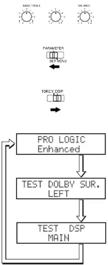
1 Set BASS, TREBLE and BALANCE on the front panel to "O" (the center position) and turn off BASS EXTENSION.
2 Sit in the main listening position and set PARAMETER/SET MENU on the remote control to PARAMETER.
3 Set 10KEY/DSP on the remote control to DSP and press ☐☐ / DTS SUR.
4 Press TEST on the remote control once or twice to select the test you want.
- Select "TEST DOLBY SUR." to match the output levels of the Center, Rear Center and left and right Rear speakers to the left and right Main speakers.
- Select “TEST DSP” to match the output levels of the Front Effect speakers to the Main speakers.
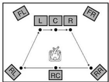
Dolby Surround Test
Use the Dolby Surround Test to balance the output levels of speakers required for surround sound systems.
flowchart
graph TD
    A["TEST DOLBY SUR. LEFT"] --> B["TEST DOLBY SUR. CENTER"]
    B --> C["TEST DOLBY SUR. RIGHT"]
    C --> D["TEST DOLBY SUR. RIGHT SURROUND"]
    D --> E["TEST DOLBY SUR. REAR CENTER"]
    E --> F["TEST DOLBY SUR. LEFT SURROUND"]
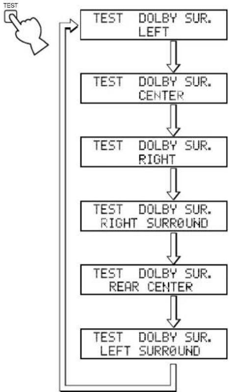
1 Press TEST on the remote control so "TEST DOLBY SUR." appears on the video monitor and front panel display.
flowchart
graph TD
    FL["FL"] --> L["L"]
    FR["FR"] --> R["R"]
    RR["RR"] --> L["L"]
    RR --> R["R"]
    L --> C["C"]
    C --> R["R"]
    R --> L["L"]
    L --> C["C"]
    C --> R["R"]
    R --> L["L"]
    L --> C["C"]
2 Adjust VOLUME +/- so you can hear the test tone.
- The test tone is produced from the left Main speaker, Center speaker, right Main speaker, right Rear speaker, Rear Center speaker and left Rear speaker in order. The tone is produced for 2.5 seconds each time.
- You can stop the sequence temporarily by pressing or .
3 Adjust the output level of the effect speakers using the cursor - or + buttons on the remote control so the output level coming from each speaker is the same.
- You can increase the output levels of the effect channels (left Rear, right Rear, Rear Center and Center) to +10 dB. If the output level of the Center, Rear, and Rear Center speakers is lower than that from the Main speakers even after you have increased the sound volume level of the Center, Rear, and Rear Center speakers up to +10 dB, set the 1G. MAIN LEVEL item in the SET MENU to “-10dB.” Setting the 1G. MAIN LEVEL item to this setting decreases the Main speaker volume level to about one-third the normal level. After you set the 1G. MAIN LEVEL item in the SET MENU to “-10dB,” adjust the levels for the Center, Rear, and Rear Center speakers again.
4 When you finish adjusting the output level of the Center, Rear, and Rear Center speakers, press TEST repeatedly until the current DSP program appears.
Note:
- The tonal quality of the speakers can be adjusted using the 7. CENTER GEQ, 8. REAR CT GEQ, and 9. CINEMA EQ items in the SET MENU (see page 45\~46).
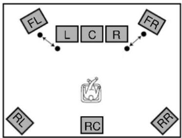
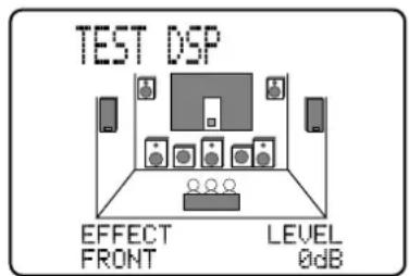
DSP Test
Adjust the output level of the Front Effect speakers while this unit is reproducing a DSP sound field program. If you do not use Front Effect speakers, set the 1F. FRNT EFCT SP item in the SET MENU to "NONE" (see page 37), and the DSP Front Effect signals will be mixed with the Main channel signals.

TEST DSP MAIN
flowchart
graph TD
    FL["FL"] --> L["L"]
    L --> C["C"]
    C --> R["R"]
    R --> FR["FR"]
    FR --> L
    L --> R
    R --> RL["RL"]
    RL --> RC["RC"]
    RC --> RR["RR"]
1 Press TEST repeatedly until "TEST DSP" appears on the video monitor and front panel display.
2 Adjust VOLUME so you can hear the test tone.
- The test tone is produced alternately from the Front Effect speakers and Main speakers. The tone is produced for 2.5 seconds each time.
3 Adjust the output level of the Front Effect speakers using + and - so the output level coming from the Front Effect speakers is the same as that of the Main speakers.
- The test tone is automatically produced from the Front Effect speakers while you are adjusting the level.
4 When you finish adjusting the output level of the Front Effect speakers, press TEST repeatedly until the current DSP program appears.
Notes:
- If you cannot hear the test tone, set VOLUME, turn off the power, and check the speaker cords and hookups.
- The test tone can be reproduced separately from the left and right Front Effect speakers. This is useful when you want to check the hookups to these speakers. Press to reproduce the test tone from the left speaker, and press to reproduce the tone from the right speaker. (The OSD shows which speaker is reproducing the tone.)
- You cannot adjust the output level of the left and right Front Effect speakers separately.
- You can stop the test tone's alternation temporarily by pressing or .
- The tonal quality of the speakers can be adjusted using the 7. CENTER GEQ, 8. REAR CT GEQ, and 9. CINEMA EQ items in the SET MENU (see page 45\~46).
- If the sound volume of the Front Effect speakers is lower than that of the Main speakers, even after you have increased the output level up to +10 dB, set the 1G. MAIN LEVEL item in the SET MENU to “-10dB.” Setting the 1G. MAIN LEVEL item to “-10dB” decreases the Main speaker output level to about one-third of the normal level.
After you set the 1G. MAIN LEVEL item in the SET MENU to “-10dB,” repeat the TEST DOLBY SUR. procedure on the previous page.
Basic Operation
Basic Playback 31
Power Control 31
Selecting a Source 32
Input Modes and Indications 33
Selecting a Sound Field Program 34
Basic Recording 35
Preparations 35
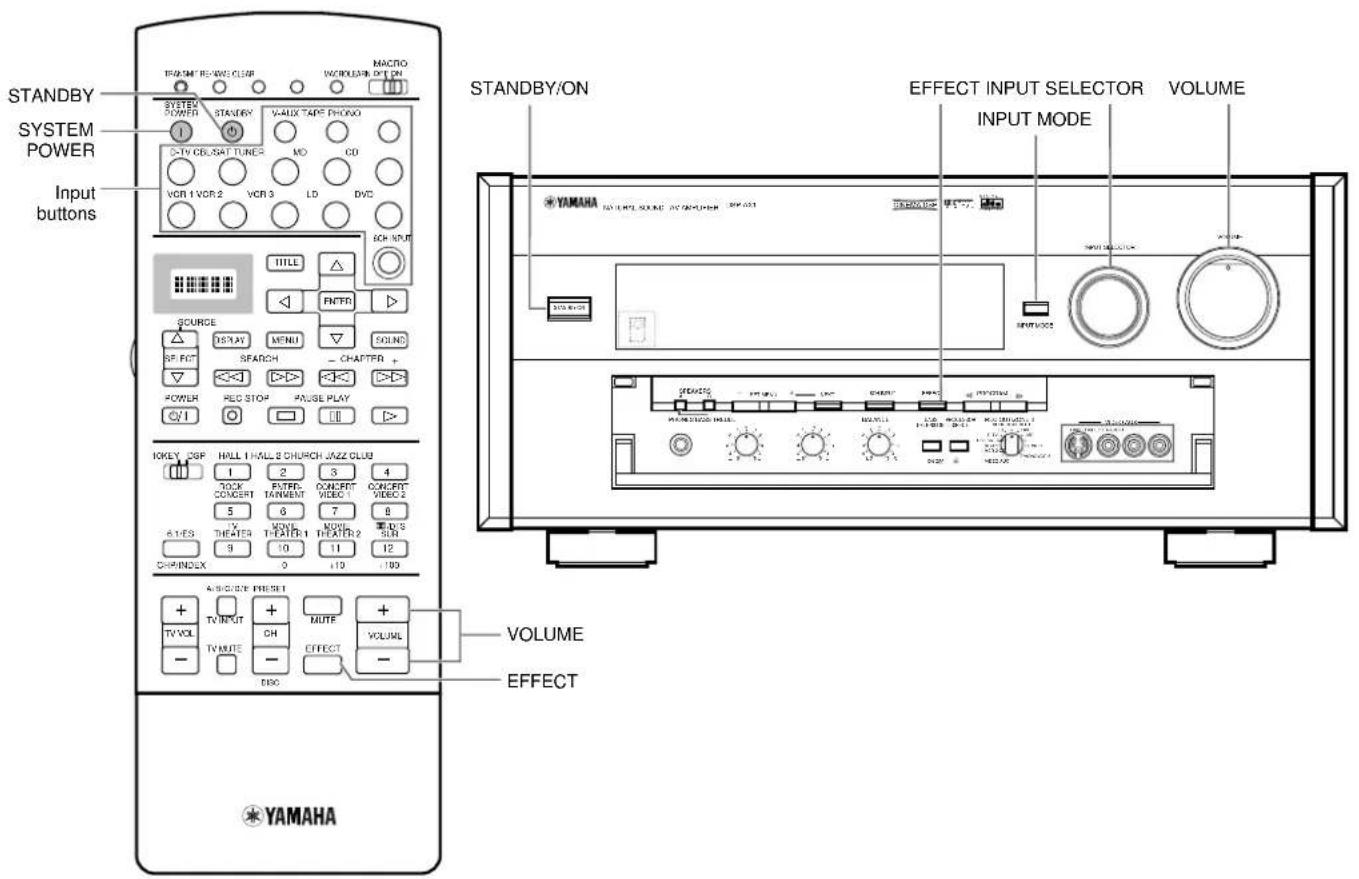
Power Control
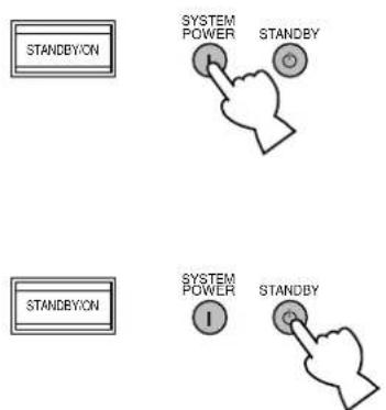
1 Press STANDBY/ON (or SYSTEM POWER on the remote control) to turn on the power.
- The front panel (and the monitor screen) shows the level of the volume for a few seconds and then switches to show the current sound field program.
2 Press STANDBY/ON (or STANDBY on the remote control) to turn off the power.
Note:
- This unit stores its current operational status in memory before the power is turned off. By connecting a commercially available timer to this unit, you can easily playback or record a source at any time you wish.
Selecting a Source
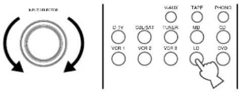
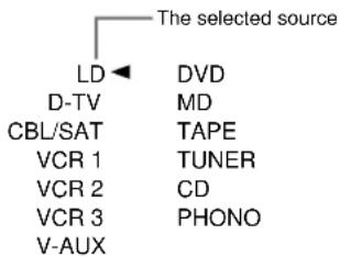
1 Select the source using INPUT SELECTOR, or press one of the input buttons on the remote control.
- The current source is indicated on the front panel display with an arrow.
- The current source name and input mode appear on the front panel display and the video monitor for a few seconds.
Select this source:
To reproduce the signal from this equipment.
DVD ...... DVD player
LD.... LD player
D-TV...... Digital TV or TV
CBL/SAT...... Cable TV or Satellite tuner
VCR 1 ...... Video deck 1
VCR 2 ...... Video deck 2
VCR 3 ...... Video deck 3
V-AUX ...... Other A/V equipment
PHONO .... Turntable
CD...... CD player
TUNER...... AM/FM tuner
TAPE TAPE deck
MD...... MD recorder
2 Start playback (or select a broadcast station) on the source equipment.
- Refer to the operation instructions for the equipment.
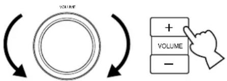
3 Adjust VOLUME (or VOLUME +/- on the remote control).
Caution:
- If the power of the equipment connected to the VCR 1, VCR 2, VCR 3, TAPE, and MD OUT jacks is turned off, reproduced sound may be distorted or the volume may be lowered. In these cases, turn on the equipment.
flowchart
graph TD
    A[" "] --> B[" "]
    B --> C[" "]
    C --> D["+"]
    C --> E["-"]
■ BGV (Back Ground Video) Function
The BGV (Back Ground Video) function allows you to combine a video signal from a video source with a sound signal from an audio source. (For example, you can listen to classical music while you are watching a video.)
Using the remote control, select a source from the video group, then select a source from the audio group. Use the input buttons on the remote control to make your selections. The BGV function does not work if you select the sources using INPUT SELECTOR on the front panel.
The DSP-AX1 comes with various input jacks. If your external component is connected to more than one type of input jack, you can set the priority of the input signal. Press INPUT MODE on the front panel or an input button (press it repeatedly) on the remote control to display or change the input mode.
• AUTO
AUTO:DOLBY DGTL
AUTO:DTS
AUTO:PCM
AUTO:ANALOG
AUTO: ---
- Dolby Digital RF
0.D.RF
D.D. RF:---
• DTS
DTS
DTS:---
• DIGITAL
DGTL:DOLBY DGTL
DGTL:DTS
DGTL:PCM
DGTL:---
• ANALOG
ANALOG
ANALOG:---
AUTO: .... This mode is automatically selected when you turn on the power of this unit. In this mode, the input signal is automatically selected in the following order.
1) Dolby Digital or DTS encoded signals
2) Digital (PCM) signals
3) Analog signals
DTS: ....In this mode, only digital input signals encoded with DTS are selected even if other signals are input at the same time.
ANALOG: ....In this mode, only analog input signals are selected even if digital signals are input at the same time.
AUTO: ....In this mode, this unit automatically selects the signal in the following order.
1) Dolby Digital RF encoded signals
2) DTS encoded signals
3) Digital (PCM) signals
4) Analog signals
D.D. RF:...... This unit only selects Dolby Digital RF signals.
DTS: ...... This unit only selects DTS signals.
DGTL:.... This unit only selects digital signals input through the OPTICAL jacks.
ANALOG: ...... This unit only selects signals input through the ANALOG jacks. This unit will not select Dolby Digital RF or DTS signals.
Notes:
- For CD, DVD, and CBL/SAT sources, if digital signals are input from both the OPTICAL and COAXIAL terminals, the digital signal from the COAXIAL terminal is selected.
- When the "AUTO" mode is selected, the DSP-AX1 automatically determines the type of signal. If the DSP-AX1 detects a DTS or Dolby Digital signal, the decoder automatically switches to the appropriate setting and reproduces 5.1 channel sound.
- When you use functions such as pause, search, or disc change while playing a disc encoded with DTS signals, the DTS indicator flashes until the next playback starts.
- If you play a disc encoded with DTS signals and the input mode is set to "ANALOG", this unit reproduces the noise of an unprocessed DTS signal. When you want to play a DTS source, be sure to connect the source to a digital input jack and set the input mode to "AUTO" or "DTS."
- If you switch the input mode to "ANALOG" while playing a disc encoded with DTS signals, this unit reproduces no sound.
- For LD software that does not contain a digital soundtrack, connect the LD player to the analog jacks and set the input mode to "AUTO" or "ANALOG."
- The input mode resets to "AUTO" after you turn off the power. When the current input source is D-TV, CBL/SAT, and VCR 1, the input mode resets to the one set using the 15. INPUT MODE item in the SET MENU after you turn off the power (see page 48).
- If the LD player is transmitting signals in a non-standard method, the DSP-AX1 cannot detect the DTS or Dolby Digital signal. In this case, the decoder automatically switches to PCM or analog.
- Some audio/video equipment, such as LD players, output different audio signals through their analog and digital jacks. Change the input mode as necessary.
Selecting a Sound Field Program
You can enhance your listening experience by selecting a DSP sound field program. The 24 DSP sound field programs are divided into 12 DSP program groups. For details about each program, see page 67\~72.
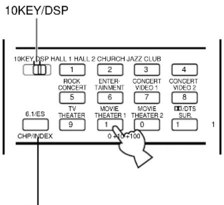
6.1/ES
If you want to utilize the Rear Center speaker with a 5.1 channel program source, press 6.1/ES. However, note that to achieve the proper effect with the rear center channel, Dolby Digital Surround EX or DTS ES software should be used.
1 Set 10KEY/DSP to DSP.
2 Press one of the DSP program group buttons (or PROGRAM◀ or ▷ on the main unit) repeatedly until the DSP program you want appears in the front panel display.
- For example, to select “Live Concert,” press HALL 2 repeatedly. You can also select sound field programs within the current group by setting PARAMETER/SET MENU to the PARAMETER position and pressing the cursor + or - button.
Notes:
- If a DTS or Dolby Digital signal is input when the input mode is set to “AUTO”, the sound field program automatically switches to the appropriate decoding program.
- Choose a sound field program based on your listening preference, not on the name of the program. The acoustics of your listening room affect the sound field program. Minimize the sound reflections in your room to maximize the effect created by the program.
- When you select an input source, the main unit automatically selects the last sound field program used with that source.
- When you turn off the main unit, the current source and sound field program are memorized and are automatically selected when you turn on the power again.
- When high rate 96kHz sampling 24 bit digital signals are output from source equipment, the DSP sound field cannot operate on the source sounds. In this case, the sounds are reproduced as normal 2-channel stereo.
Hi-Fi DSP Programs
| 1 | 2 | Church | Jazz Club | Rock Concert | Entertainment |
| Europe Hall A | U.S.A. Hall D | Tokyo | Village Gate | Roxy Theatre | Disco |
| Europe Hall B | Europe Hall E | Freiburg | Village Vanguard | Warehouse Loft | Party |
| Europe Hall C | Live Concert | Royaumont | The Bottom Line | Arena | Game/Amusement |
CINEMA-DSP Programs
| Concert Video 1 | Concert Video 2 | TV Theater | Movie Theater 1 | Movie Theater 2 | ☐/ DTS SURROUND |
| Pop/RockDJ | Classical/Opera Pavilion | Mono Movie Variety/Sports | Spectacle Sci-Fi | Adventure General | Normal/Matrix 6.1/ES Enhanced/6.1/ES |
■ Virtual CINEMA DSP and HP CINEMA DSP
You can experience the virtual CINEMA DSP sound field by setting the 1C. REAR L/R SP item in the SET MENU to “NONE.” The sound field processing is changed to the Virtual CINEMA DSP mode according to the selected sound field program. Virtual CINEMA DSP is performed using the Main speakers. You can also listen to HP (Headphone) CINEMA DSP by connecting your headphones to the PHONES jack while the DSP sound fields are on.
EFFECT

EFFECT OFF
■ Normal Stereo Reproduction
For normal stereo reproduction, press EFFECT to turn off the effect.
Notes:
- When you turn off the effect, no sound is reproduced from the Front Effect, Center, Rear, and Rear Center speakers.
- If you turn off the effect while DTS or Dolby Digital signals are being reproduced, the dynamic range of the signal is automatically compressed.
- The sound volume may be extremely reduced when you turn off the effect or if you change SET MENU item 3B. D-RANGE to MIN. In this case turn on the effect.
REC OUT/ZONE 2 allows you to record one source while viewing and/or listening to another source.
Preparations
REC OUT/ZONE 2
SOURCE/REMOTE
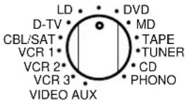
1 Turn on the power to the DSP-AX1 and all connected equipment.
2 Select the source equipment you want to record using REC OUT/ZONE 2.
- To record the current source, set REC OUT/ZONE 2 to SOURCE/REMOTE.
- To record a source that you do not want to reproduce, set REC OUT/ZONE 2 to the source you want to record.
3 Start playback (or select a broadcast station) on the source equipment.
4 Start recording on the recording equipment
- If you want to listen to another source, and REC OUT/ZONE 2 is not set to SOURCE/REMOTE, select the source you want to reproduce with INPUT SELECTOR and adjust the volume.
Notes:
- Do a test recording before you start an actual recording.
- When this unit's power is off, you cannot record between other equipment connected to this unit.
- Operating BASS and TREBLE, BASS EXTENSION, BALANCE, VOLUME, and DSP programs do not affect the recorded signal.
Caution:
- The DUF (AC-3) input signal cannot be output using REC OUT/ZONE 2.
■ Special considerations when recording DTS software
The DTS signal is a digital bitstream. Attempting to digitally record the DTS bitstream will result in noise being recorded. Therefore, if you want to use this unit to record sources that have DTS signals recorded on them, the following considerations need to be made.
For DTS encoded LDs, DVDs, and CDs:
Only 2-channel analog audio signals may be recorded as follows:
Laser Discs:
Set your Laser Disc player's left and right outputs to the analog soundtrack.
DVDs:
Use the disc menu to set the DVD player's mixed 2-channel left and right audio outputs to the PCM or Dolby Digital soundtrack.
Compact Discs:
The DTS signal recorded on CDs can only be output as a digital bitstream, and therefore cannot be recorded.
Advanced Operation
Operating the SET MENU 38
-
SPEAKER SET (1A. CENTER SP to 1G. MAIN LEVEL) ...... 39
-
LOW FREQ. TEST 42
-
DOLBY D. SET (Dolby Digital Set) 43
-
DTS SET 44
-
SP DELAY TIME 44
-
AUDIO DELAY 44
-
CENTER GEQ (Center Graphic Equalizer) 45
-
REAR CT GEQ (Rear Center Graphic Equalizer) 45
-
CINEMA EQ 46
-
HP TONE CTRL (Headphone Tone Control) 47
-
PARAMETER INI (Parameter Initialization) 47
-
6.1/ES AUTO 47
-
MEMORY GUARD 48
-
CMPNT-V INPT (Component Video Input) 48
-
INPUT MODE 48
-
INPUT RENAME 49
-
DIMMER 49
-
ZONE 2 SET .... 49
Remote Control Features 50
Using the Remote Control 50
Each Component Control Area 52
Operating a Tuner (TUNER Area) 52
Operating a Tape Deck (TAPE Area) 52
Operating a CD Player (CD Area) 53
Operating an MD Recorder (MD Area) 53
Operating an LD Player (LD Area) 54
Operating a DVD Player (DVD Area) 54
Operating a VCR (VCR 1 / VCR 2 / VCR 3 Area) 55
Operating a TV or Digital TV (D-TV Area) 55
Operating a Cable or Satellite TV Tuner (CBSAT Area) 56
Free Area (OPTN and PHONO Areas) 56
Setting the Manufacturer Code in the Remote Control 57
Programming a New Remote Control Function 58
Using the Macro Feature 59
Changing the Source Name in the Display Window 61
Clearing a Learned Function or Macro 61
Clearing Learned Functions, Macros, Renamed Displays,
and Manufacturer Setups 62
Adjusting the Levels of the Effect Speakers 63
Setting the Sleep Timer 63
ZONE 2 64
Connections 64
Remote Control in ZONE 2 65
The SET MENU consists of eighteen items including the Speaker Set, Center Graphic Equalizer and Parameter Initialization features. Choose the appropriate item and adjust or select the values as necessary.
Notes:
- You can adjust the items in the SET MENU while reproducing a source.
- We recommend that you adjust the items in the SET MENU while using a video monitor. It is easier to see the video monitor screen than it is to see the front panel display on this unit while adjusting SET MENU items.
| Items | Descriptions | Setting (Bold as default) | Page |
| 1. SPEAKER SET1A. CENTER SP1B. MAIN SP1C. REAR L/R SP1D. REAR CT SP1E. LFE/BASS OUT1F. FRNT EFCT SP1G. MAIN LEVEL | Selects the output mode suitable for your Center speaker.Selects the output mode suitable for your Main speakers.Selects the output mode suitable for your Rear speakers.Selects the output mode suitable for your Rear Center speaker.Selects the speakers for your LFE/BASS signal output.Selects the output mode for your Front Effect speakers.Selects the output level for your main channels. | LRG / SML / NONELARGE / SMALLLRG / SML / NONELRG / SML / NONESW / MAIN / BOTHYES / NONENormal / -10 dB | 39393940404141 |
| 2. LOW FREQ. TEST | Matches the Subwoofer level with the level of the other speakers. | TEST TONE: OFF / ONOUTPUT: MAIN L/R, MAIN L, CENTER,MAIN R, R SUR.(REAR R), REAR CT,L SUR.(REAR L), SUBWOOFER, FRONTFREQ.: 35 Hz-250 Hz | 42 |
| 3. DOLBY D. SET3A. LFE LEVEL3B. D-RANGE | Adjusts the output level of the LFE channel for Dolby Digital signals.Adjusts the dynamic range for Dolby Digital signals. | SPEAKER: -20 dB to 0 dBHEADPHONE: -20 dB to 0 dBSP(SPEAKER): MAX / STD / MINHP(HEADPHONE): MAX / STD / MIN | 43 |
| 4. DTS SET4A. LFE LEVEL | Adjusts the output level of the LFE channel for DTS signals. | SPEAKER: -10 dB to +10 dB (0 dB)HEADPHONE: -10 dB to +10 dB (0 dB) | 44 |
| 5. SP DELAY TIME | Adjusts the delay time for Center and Rear Center speakers. | CENTER: 0 ms to 5 msREAR CNTR: 0 ms to 30 ms (3 ms) | 44 |
| 6. AUDIO DELAY | Adjusts the delay time for all channels. | 0 ms to 99 ms | 44 |
| 7. CENTER GEQ | Matches the Center speaker tonal quality with the Main speakers. | 5-band: -6 dB to +6 dB (0 dB) | 45 |
| 8. REAR CT GEQ | Controls the tonal quality of the Rear Center speaker. | 5-band: -6 dB to +6 dB (0 dB) | 45 |
| 9. CINEMA EQ9A. L, C, R EQ9B. FRNT EFCT EQ9C. REAR L/R EQ9D. REAR CT EQ | Adjusts the tonal balance of the Main and Center speakers, Front Effect speakers,Rear speakers and Rear Center speaker separately. | LCR, FRNT EFCT, REAR L/R, REAR CT: OFF / ONHIGH-FRQ: 1 kHz to 12.7 kHzGAIN: -9 dB to +6 dB (-3 dB or 0 dB)PEQ-FRQ: 1 kHz to 12.7 kHz (8 kHz or 12.7 kHz)GAIN: -9 dB to +6 dB (-3 dB or -4 dB) | 46 |
| 10. HP TONE CTRL | Adjusts the tonal balance of the headphones. | BASS, TRBL: -6 dB to +3 dB (0 dB) | 47 |
| 11. PARAMETER INI | Initializes the parameters of a group of DSP programs. | 1 to 12 | 47 |
| 12. 6.1/ES AUTO | Selects the AUTO mode of Dolby Digital/Matrix 6.1and DTS ES decoding. | ON / OFF | 47 |
| 13. MEMORY GUARD | Locks DSP program parameters and other SET MENU settings. | OFF / ON | 48 |
| 14. CMPNT-V INPT | Selects the equipment to be connected to the component video inputs A, B or C. | A: DVDB: D-TVC: CBL/SAT | 48 |
| 15. INPUT MODE | Selects the initial input mode of the sources connected to D-TV, CBL/SAT and VCR 1. | D-TV: AUTO / LASTCBL/SAT: AUTO / LASTVCR1: AUTO / LAST | 48 |
| 16. INPUT RENAME | Changes the name of the inputs. | Up to eight characters. | 49 |
| 17. DIMMER | Adjusts the brightness of the front panel display. | -4 to 0 | 49 |
| 18. ZONE 2 SET | Selects the mode of Zone 2. | ZONE 2 OUT: FIX(fixed) / VAR.(variable) | 49 |
This section describes how to adjust items in the SET MENU using the remote control. To make adjustments using the controls on the main unit, use the buttons referred to in parentheses.
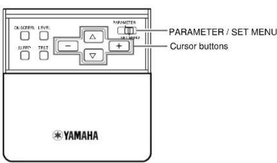
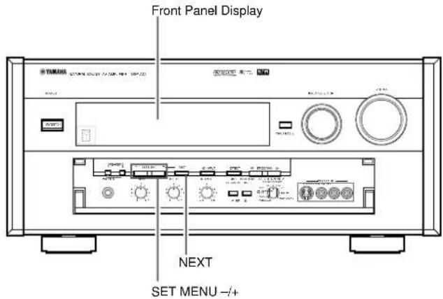
■ General procedure for adjusting items
Some items require extra steps to change to the desired setting.

2 Press or (or NEXT) repeatedly to select an item, then press + or - (or SET MENU + or -) to change the setting of that item.
- The last item you adjusted appears on the front panel display (or in the SET MENU OSD if you are using a video monitor).
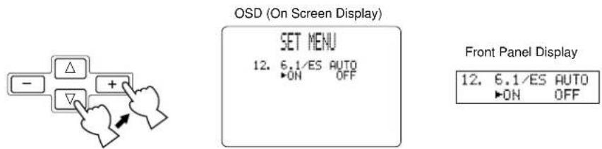
- If "Press + / - Key!" appears on the display, press + or - (or SET MENU + or -) to select an item, press △ or ▽ (or NEXT) to select a sub item, and then press + or - (or SET MENU + or -) to change the setting of that item.
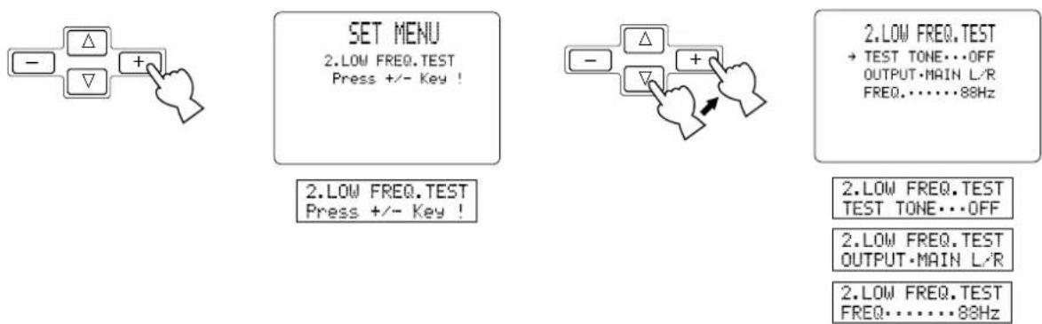
3 Press or (or NEXT) repeatedly or a DSP program button to exit the SET MENU.
Note:
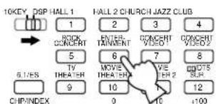
- NEXT on the main unit works the same as on the remote control. It does not work as .
1. SPEAKER SET (1A. CENTER SP to 1G. MAIN LEVEL)
Use this feature to select suitable output modes for your speaker configuration. You must set the output mode when you use a subwoofer.
■ 1A. CENTER SP (Center Speaker Mode)
By adding a Center speaker to your speaker configuration, the DSP-AX1 can provide good dialogue localization for many listeners and superior synchronization of sound and images. The OSD shows a large, small or no center speaker depending on how you set this item. The initial setting is “LRG”.
Select the “LRG” (Large) setting if you have a large Center speaker. The entire range of Center channel signals is sent to the Center speaker.
Select the “SML” (Small) setting if you have a small Center speaker. Center channel low frequency signals of 90 Hz and below are directed to the speakers selected with the 1E. LFE/BASS OUT item (see page 40).
Select the “NONE” setting if you do not have a Center speaker. All of the Center channel signals are directed to the left and right Main speakers. The “NONE” position provides good dialogue localization for the person sitting in the main listening position.
Large
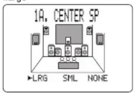
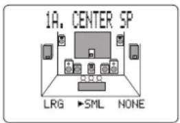
NoneSmall
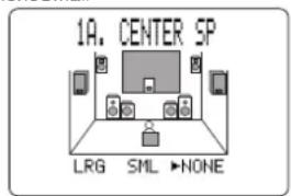
1A. CENTER SP
▶LRG SML NONE
■ 1B. MAIN SP (Main Speaker Mode)
The display shows small or large Main speakers depending on how you set this item. The initial setting is “LARGE”.
Select the “LARGE” setting if you have large Main speakers. The entire range of left and right Main channel signals is directed to the left and right Main speakers.
Select the “SMALL” setting if you have small Main speakers. The Main channel low frequency signals of 90 Hz and below are directed to the speakers selected with the 1E. LFE/BASS OUT item (see page 40).
Large Small
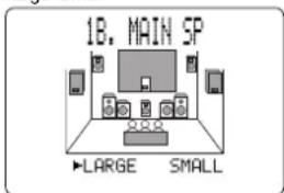
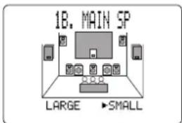
1B. MAIN SP
▶LARGE SMALL
Note:
- When you select the “MAIN” setting for the 1E. LFE/BASS OUT item, the Main channel low frequency signals of 90 Hz and below are directed to the Main speakers even if you select the “SMALL” setting for the Main speaker mode. In this case, the OSD shows large Main speakers.
■ 1C. REAR L/R SP (Rear Speaker Mode)
The OSD shows large, small or no Rear speakers depending on how you set this item. The initial setting is “LRG”.
Select the “LRG” setting if you have large left and right Rear speakers or if you use a Rear Subwoofer (see page 22). The entire range of Rear channel signals is sent to the left and right Rear speakers.
Select the “SML” setting if you have small left and right Rear speakers. Rear channel low frequency signals of 90Hz and below are directed to the speakers selected with the 1E. LFE/BASS OUT item (see page 40).
Select the "NONE" setting if you do not have Rear speakers.
- In this case, Rear Center speaker will automatically be set to "NONE" and the 1D. REAR CT SP item will be skipped.
Large Small
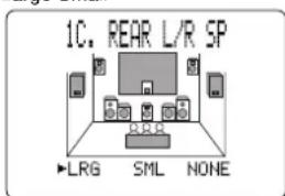
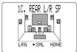
None
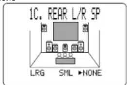
1C. REAR L/R SP
▶LRG SML NONE
■ 1D. REAR CT SP (Rear Center Speaker Mode)
By adding a Rear Center speaker to your speaker configuration, the DSP-AX1 can provide more realistic front-to-back and back-to-front transitions. The initial setting is "LRG".
Select the "LRG" setting if you have a large Rear Center speaker. The entire range of Rear Center channel signals is sent to the Rear Center speakers.
Select the “SML” (small) setting if you have a small Rear Center speaker. Rear Center channel low frequency signals of 90 Hz and below are distributed to speakers selected with the 1E. LFE/BASS OUT item.
Select the "NONE" setting if you do not have a Rear Center speaker.
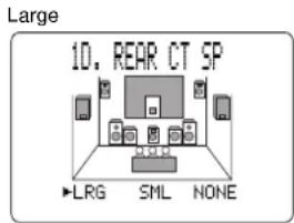
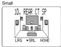
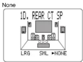
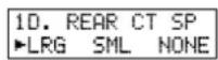
■ 1E. LFE/BASS OUT (Bass Out Mode)
LFE signals carry low frequency effects when this unit decodes DTS or Dolby Digital signals. Low frequency signals are defined as 90 Hz and below. The initial setting is “BOTH”.
Select the "SW" (Subwoofer) setting if you use a Subwoofer. The LFE signals are directed to the Subwoofer.
Select the "MAIN" setting if you do not use a Subwoofer. The LFE signals are directed to the Main speakers.
Select the “BOTH” setting if you use a Subwoofer and you want to mix the Main channel low frequency sound signals with the LFE signals.
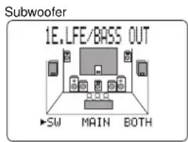
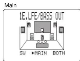
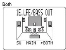
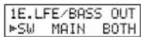
Note:
- The low frequency signals of 90Hz and below from all Main, Center, Rear and Rear Center channels are directed to the LFE channel when you select the small speaker setting in items 1A, 1B, 1C and 1D.
■ 1F. FRNT EFCT SP (Front Effect Speaker Mode)
The DSP-AX1 uses Front Effect speakers to localize the virtual sound sources of the sound field programs. If you do not use Front Effect speakers, you can direct the Front Effect signals to the Main speakers.
The OSD shows small or no Front Effect speakers depending on how you set this item. The initial setting is "YES".

Select the "YES" setting if you use Front Effect speakers.

Select the “NONE” setting if you do not use Front Effect speakers. The Front Effect signals are mixed with the Main channels.
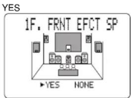
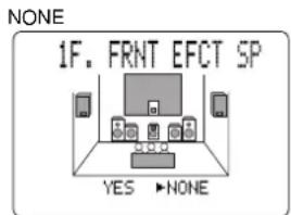
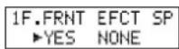
■ 1G. MAIN LEVEL
Change this setting if you cannot match the sound volume of the Front, Rear, and Center speakers with the Main speakers because of the unusually high efficiency performance of the Main speakers. The initial setting is “Normal”.

Select the “Normal” setting if you can match the volume of your effect speakers with the volume of your Main speakers using the Dolby Surround Test (page 28).

Select the “-10dB” setting if you cannot match the volume of your effect speakers with the volume of your Main speakers using the Dolby Surround Test (page 28).
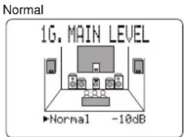
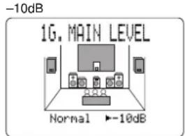
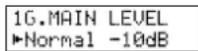
Note:
- When this unit decodes 96 kHz sampling/24 bit digital signals or 6CH INPUT is on, level adjustments in items 1A\~1F are not possible.
2. LOW FREQ. TEST
Use this feature to adjust the Subwoofer volume so it matches the volume of the other speakers in your configuration. Change the setting using the remote control while sitting in the main listening position.
1 Press + or - (or SET MENU + or -) to set TEST TONE to "ON", and adjust the volume using VOLUME + (or VOLUME) so you can hear the tone.
2 Press ∇ (or NEXT) repeatedly to go to OUTPUT and press + or - (or SET MENU + or -) to select the speaker you want to compare with the Subwoofer.
- If “SUBWOOFER” is selected, test tones above 90 Hz will not be output from the Subwoofer. The test tone will not necessarily be output from the selected speakers. The output mode of the test tone depends on the settings of the 1. SPEAKER SET items in the SET MENU.
3 Press ▽ (or NEXT) repeatedly to go to FREQ. and press + or - (or SET MENU + or -) to select the frequency you want to use.
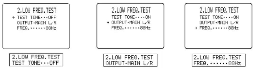
4 Adjust the Subwoofer volume using the controls on the Subwoofer so it matches the volume of the speaker you are comparing it to.
Notes:
- Do not turn up the VOLUME too high.
- If no test tone is heard, turn off the power and make sure all the necessary hookups are correct.
Digital Generator
(Wide Band Noise Produced)
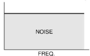
Band Pass Filter
Center freq.

35 Hz\~250 Hz

■ About the Test Tone
The test tone is produced by the tone generator.
The tone generator produces a narrow band noise centered at a specified frequency by the band pass filter.
You can change the center frequency from 35 Hz through 250 Hz in one-sixth octave steps.
You can use the test tone not only for adjusting the subwoofer level, but also for checking the low frequency characteristics of your listening room. Low frequency sounds are especially affected by the listener's position, speaker placement, subwoofer polarity and other conditions.
3. DOLBY D. SET (Dolby Digital Set)
■ 3A. LFE LEVEL
Use this feature to adjust the output level of the LFE (low frequency effect) channel when playing back Dolby Digital encoded software. This setting is effective only when this unit decodes Dolby Digital signals. The LFE signal carries the low frequency special effect sound which is only added to certain scenes.
You can adjust the levels from 0 dB to -20 dB.
- Adjust the LFE levels according to the capacity of your subwoofer or headphones.
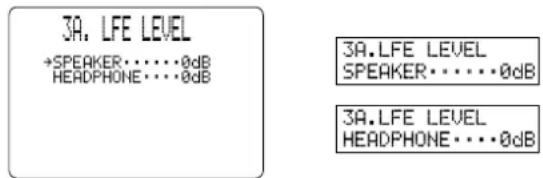
■ 3B. D-RANGE (Dynamic Range)
Use this feature to adjust the dynamic range. This setting is effective only when this unit decodes Dolby Digital signals.
Select the "MAX" setting for feature films.
Select the "STD" (Standard) setting for general use.
Select the “MIN” setting for listening to sources at extremely low volume levels.
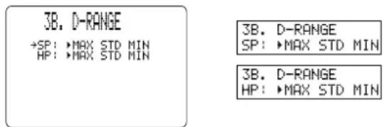
Note:
- When D-RANGE is set to “MIN”, sound output may be faint because some Dolby Digital software is not compatible with the minimum level dynamic range.
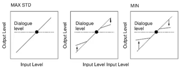
4. DTS SET
■ 4A. LFE LEVEL
Use this feature to adjust the output level of the LFE (low frequency effect) channel when playing back DTS encoded software. This setting is effective only when this unit decodes DTS signals. The LFE signal carries the low frequency special effect sound which is only added to certain scenes.

You can adjust the levels from -10 dB to +10 dB.
- Adjust the LFE level according to the capacity of your subwoofer or headphones.
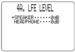
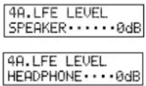
5. SP DELAY TIME
Use this feature to adjust the delay of the Center and the Rear Center channel sounds. This feature works when this unit decodes DTS or Dolby Digital signals. Ideally, the Center speaker and the Rear Center speaker should be the same distance from the main listening position as the left and right Main speakers. However, in most home situations, the Center speaker or the Rear Center speaker is placed in line with the Main speakers or the Rear speakers. By delaying the sound from the Center speaker and the Rear Center speaker, the apparent distance from the Center speaker and the Rear Center speaker to the main listening position can be adjusted to make it seem the same as the distance between the left and right Main speaker, and the left and right Rear speakers to the listening position. Adjusting the delay time for the Center speaker is especially important for giving depth to the dialogue.

You can adjust the delay time from 0 ms to 5 ms for the Center speaker and from 0 ms to 30 ms for the Rear Center speaker.
- Increasing the delay 1 ms simulates moving the speakers about 30 cm (one foot) farther away from the listening position.
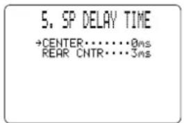
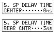
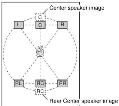
flowchart
graph TD
    A["L"] --> B["C"]
    B --> C["R"]
    C --> D["Center speaker image"]
    D --> E["RL"]
    E --> F["RC"]
    F --> G["RR"]
    G --> H["Center speaker image"]
    H --> I["Center speaker image"]
    I --> J["Center speaker image"]
    J --> K["Center speaker image"]
    K --> L["Center speaker image"]
    L --> M["Center speaker image"]
    M --> N["Center speaker image"]
    N --> O["Center speaker image"]
    O --> P["Center speaker image"]
    P --> Q["Center speaker image"]
    Q --> R["Center speaker image"]
    R --> S["Center speaker image"]
6. AUDIO DELAY
Use this feature to adjust the delay time of all channel sounds, when this unit decodes DTS or Dolby Digital signals. Adjusting AUDIO DELAY is especially important for matching the sounds to screen pictures. Initial settings is “0ms”.

You can adjust the delay time from 0ms to 99ms.
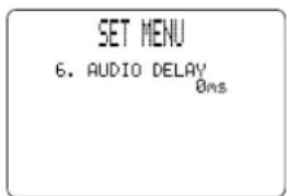
7. CENTER GEQ (Center Graphic Equalizer)
Use this feature to adjust the built-in five band graphic equalizer so the Center speaker tone matches that of the left and right Main speakers. You can select the 100 Hz, 300 Hz, 1 kHz, 3 kHz, or 10 kHz frequencies.
1 Use to select a higher frequency and to select a lower frequency.
2 Press + or - (or SET MENU + or -) to adjust the level of that frequency.

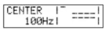
Note:
- You can monitor the Center speaker sound while adjusting this item using the Dolby Surround test tone generator. Press TEST before starting the procedure above. "TEST DOLBY SUR." appears, and the test tone starts alternating among the speakers. Once you begin the procedure above, the test tone remains at the Center speaker and you can hear how the sound changes as you adjust the various frequency levels. To turn off the test tone generator, press TEST repeatedly until the current DSP program appears (see page 28).
8. REAR CT GEQ (Rear Center Graphic Equalizer)
Use this feature to adjust the built-in five band graphic equalizer so the Rear Center speaker tone matches that of the left and right Main speakers.
1 Use to select a higher frequency and to select a lower frequency.
2 Press + or - (or SET MENU + or -) to adjust the level of the selected frequency.
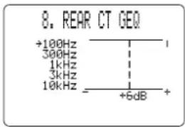
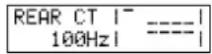
9. CINEMA EQ
Use this feature to match the tonal quality of four groups of speakers: the Main and Center speaker group, the Front Effect speakers group, the Rear speakers group, and the Rear Center speaker group. CINEMA-EQ consists of a high-shelving equalizer (HIGH) and a parametric equalizer (PEQ). The high-shelving equalizer changes high frequency characteristics, and the parametric equalizer boosts or cuts any selected frequency. The equalizer can be used for a variety of purposes, such as adjusting the tonal quality of differing types of speakers, adjusting the tonal quality in different installation environments, or adjusting the source sound to your liking.
The CINEMA EQ characteristic charts below show the value of the CINEMA EQ factory settings for each speaker group for general listening conditions.
▲ L.C.R. Preset Value
HIGH : FRQ 12.7 kHz GAIN -3 dB
PEQ : FRQ 12.7 kHz GAIN -4 dB
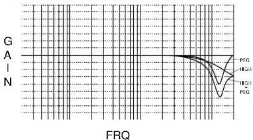
line
| FRQ | Value |
| --- | ----- |
| Peak | High |
| Low | Low |
▲ FRONT and REAR Preset Value
HIGH : FRQ 12.7 kHz GAIN 0dB
PEQ : FRQ 8.0 kHz GAIN -3dB
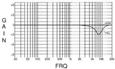
line
| FRQ | GAIN |
|-------|------|
| 20 | 0 |
| 50 | 0 |
| 100 | 0 |
| 200 | 0 |
| 500 | 0 |
| 1k | 0 |
| 2k | 0 |
| 5k | -3 |
| 10k | -3 |
| 20k | -3 |
If you want to change the characteristics, follow the procedure below to adjust the frequency and gain for the high-shelving equalizer (HIGH) and parametric equalizer (PEQ). For the more detailed characteristics in different settings, see “CINEMA-EQ Frequency Characteristics” on page 82.
1 Press ∇or△ (or NEXT) repeatedly to select one of the speaker groups and press + (or SET MENU +) to select "ON".
2 Press ∇or△ (or NEXT) repeatedly to select one of the following parameters, then press + or - (or SET MENU + or -) to change the setting of that parameter.
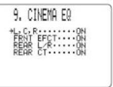
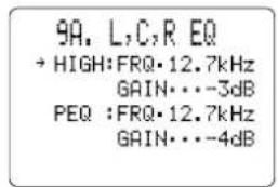
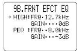
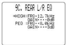
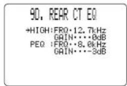
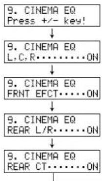
flowchart
graph TD
    A["9. CINEMA EQ Press +/- key!"] --> B["9. CINEMA EQ L,C,R......ON"]
    B --> C["9. CINEMA EQ FRNT EFCT......ON"]
    C --> D["9. CINEMA EQ REAR L/R......ON"]
    D --> E["9. CINEMA EQ REAR CT......ON"]
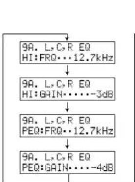
flowchart
graph TD
    A["9A. L, C, R EQ\nHI:FRQ...12.7kHz"] --> B["9A. L, C, R EQ\nHI:GAIN...-3dB"]
    B --> C["9A. L, C, R EQ\nPEQ:FRQ...12.7kHz"]
    C --> D["9A. L, C, R EQ\nPEQ:GAIN...-4dB"]
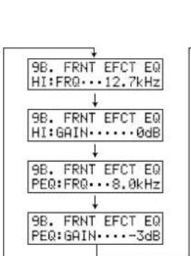
flowchart
graph TD
    A["9B. FRNT EFCT EQ\nHI:FRQ...12.7kHz"] --> B["9B. FRNT EFCT EQ\nHI:GAIN...0dB"]
    B --> C["9B. FRNT EFCT EQ\nPEQ:FRQ...8.0kHz"]
    C --> D["9B. FRNT EFCT EQ\nPEQ:GAIN...-3dB"]
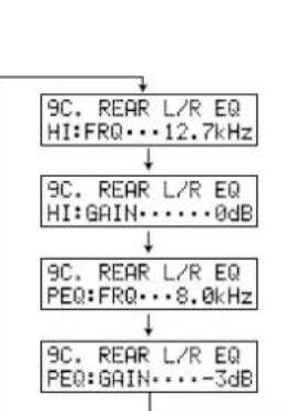
flowchart
graph TD
    A["9C. REAR L/R EQ HI:FRQ...12.7kHz"] --> B["9C. REAR L/R EQ HI:GAIN...0dB"]
    B --> C["9C. REAR L/R EQ PEQ:FRQ...8.0kHz"]
    C --> D["9C. REAR L/R EQ PEQ:GAIN...-3dB"]
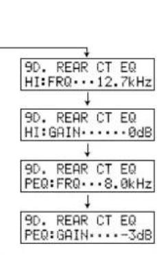
flowchart
graph TD
    A["90. REAR CT EQ HI:FRQ...12.7kHz"] --> B["90. REAR CT EQ HI:GAIN...0dB"]
    B --> C["90. REAR CT EQ PEQ:FRQ...8.0kHz"]
    C --> D["90. REAR CT EQ PEQ:GAIN...-3dB"]
• Each time you press (or NEXT), the parameter changes on the front panel display as shown above. Press the cursor to go in the reverse order.
Notes:
- When the 1F. FRNT EFCT SP item is set to "NONE", the Front Effect signals are output from the Main speakers.
• CINEMA-EQ does not work when you press EFFECT to turn off the effect.
10. HP TONE CTRL (Headphone Tone Control)
Use this feature to adjust the level of bass and treble when you use your headphones. The initial Setting is 0 dB for both bass and treble. This does not effect to the 96 kHz sampling digital signal.
Select BASS or TRBL and press + or - to change each level. You can adjust the level from -6 dB to +3 dB.
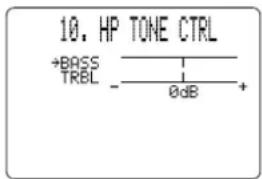
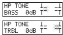
11. PARAMETER INI (Parameter Initialization)
Use this feature to initialize the parameters for each DSP program within a DSP program group. When you initialize a DSP program group, all of the parameter values within that group revert to their initial settings.
Press the DSP program group button on the remote control for the DSP program you want to initialize.
- All of the DSP programs within the selected program group are initialized.
Repeat this step to initialize other DSP program groups.
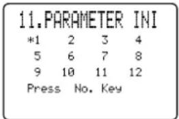
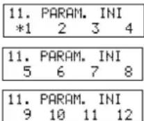
Notes:
- The asterisk (*) mark next to a DSP program group number indicates that you have changed the parameter values in one or more DSP programs within that group.
- The parameter values of the DSP programs do not change if you initialize a program group that does not have the asterisk (*) mark.
- When the MEMORY GUARD function is set to "ON" (see page 48), you cannot initialize any program groups.
- You cannot initialize the individual DSP programs within a group separately.
Caution:
- Once you initialize a DSP program group, you cannot have this unit revert the parameter values back to the previous settings automatically.
12. 6.1/ES AUTO
Use this feature to switch the DOLBY Digital Matrix 6.1 and DTS ES AUTO mode on or off.
Select “ON” to allow the main unit to automatically turn on the Dolby Digital Matrix 6.1 or DTS ES decoder when the software with identification signal is detected.
Select "OFF" if you want to control the mode manually by pressing 6.1/ES on the remote.
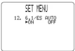
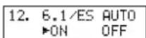
13. MEMORY GUARD
Use this feature to prevent accidental changes to DSP program parameter values and other settings on this unit.

Select "ON" to use MEMORY GUARD to protect the following features:
- DSP program parameters
- All SET MENU items
- Front, Rear, Center speaker and Subwoofer levels
• The On-Screen Display mode
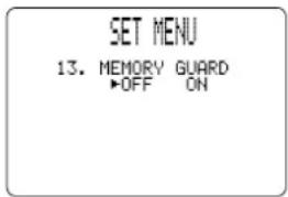
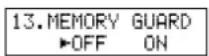
Notes:
- When MEMORY GUARD is "ON", you cannot use any of the test modes.
- When MEMORY GUARD is "ON", you cannot select any other SET MENU item.
Use this feature to designate the input for each COMPONENT VIDEO terminal, A, B, and C. The initial settings are as written on the rear panel. (Terminal A is for DVD, terminal B is for D-TV, and terminal C is for CBL/SAT.)
1 Select [A], [B], or [C] according to which terminal your equipment is connected to by pressing or .
2 Select the video input for your equipment by pressing + or -.
- You cannot select the same input once you have already selected it.
![14.CMPNT-V INPT + [A].... DVD [B].... B TU [C].... CBL/SAT](/content/2026/02/379922/images/134ff09ba28a41ed60301617ad61a4c502a207f7e70e4d6c86b8855d14d103f1.jpg)
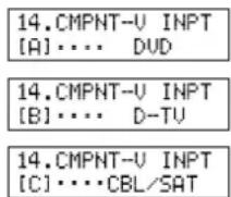
Use this feature to designate the input mode for sources connected to D-TV, CBL/SAT and VCR 1 input jacks when you turn on this unit.
Select "AUTO" to allow this unit to automatically detect the type of input signal and select the appropriate input mode.
Select “LAST” to set this unit to automatically select the last input mode used for that source.
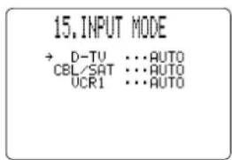
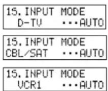
Use this feature to change the name of the input which appears on the OSD or the front panel display.
1 Select the input you want to change the name of by pressing an input button (or using INPUT SELECTOR).
2 Press + or - to place the ^ under the space or the character you want to edit.
3 Press or to select the character you want to use and + or - to move to the next one.
- Press to change the character in the following order, or press to go in the reverse order.
A\~Z, a space, 0\~9, a space, a\~z, a space, #, *, +, and so on.
- Follow the procedure above to rename other inputs.
4 Press + or - repeatedly to exit the INPUT RENAME mode.
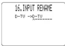
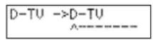
17. DIMMER
You can adjust the brightness of the front panel display from -4 to 0.
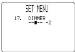
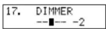
18. ZONE 2 SET
Use this feature to change the volume control setting for audio output to ZONE 2.
Selecting "VAR." allows you to control the volume output to ZONE 2 with the remote control.
Select “FIX” when you don’t want to change the volume output to ZONE 2 with the remote control.
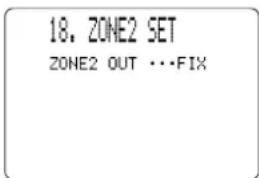
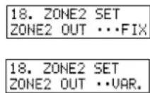
Remote Control Features
The remote control can operate the main unit as well as other Yamaha audio and video components. To control the components of other manufacturers (or some Yamaha), you must set up the remote control with the manufacturer's codes. This remote control also has a sophisticated Learn feature that allows it to acquire functions from the remote controls of other components in your system (or other household appliances) equipped with infrared remote control receivers. The Macro feature allows you to program a series of operations in sequence onto a single button, or use the factory preset macros to operate other Yamaha components. These features make it possible for you to reduce the number of remote control units in your entertainment room.
Notes:
- For operating distance of the remote control and notes about batteries, refer to page 5.
- For the name and function of each part and button, refer to pages 8 and 9.
- If the memory in the remote control becomes full, no further learning is possible even if there are still some programmable buttons available.
Using the Remote Control
The main unit control area is the shaded area shown below. It is for controlling the DSP-AX1. You can use functions within this area no matter which Component Control Area is selected.
The component control area is the shaded area shown below. Each component has different functions for operation buttons in the component control area. The component, which was chosen by pressing an input button, can be controlled and the display window shows the corresponding name of the input.
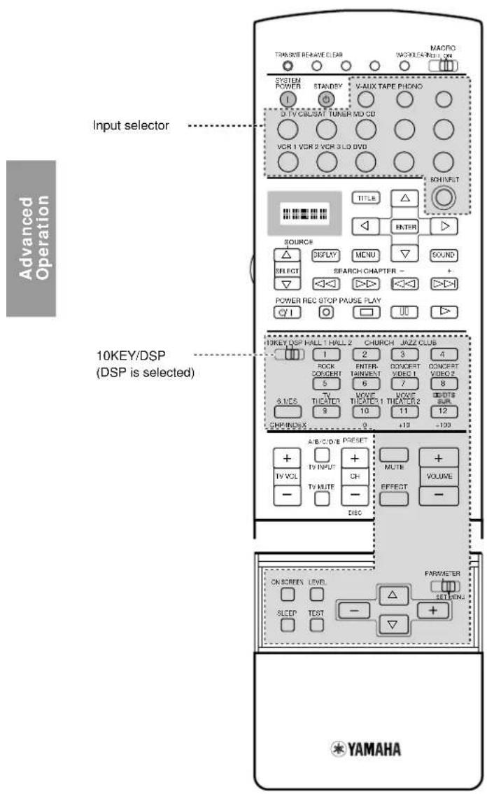
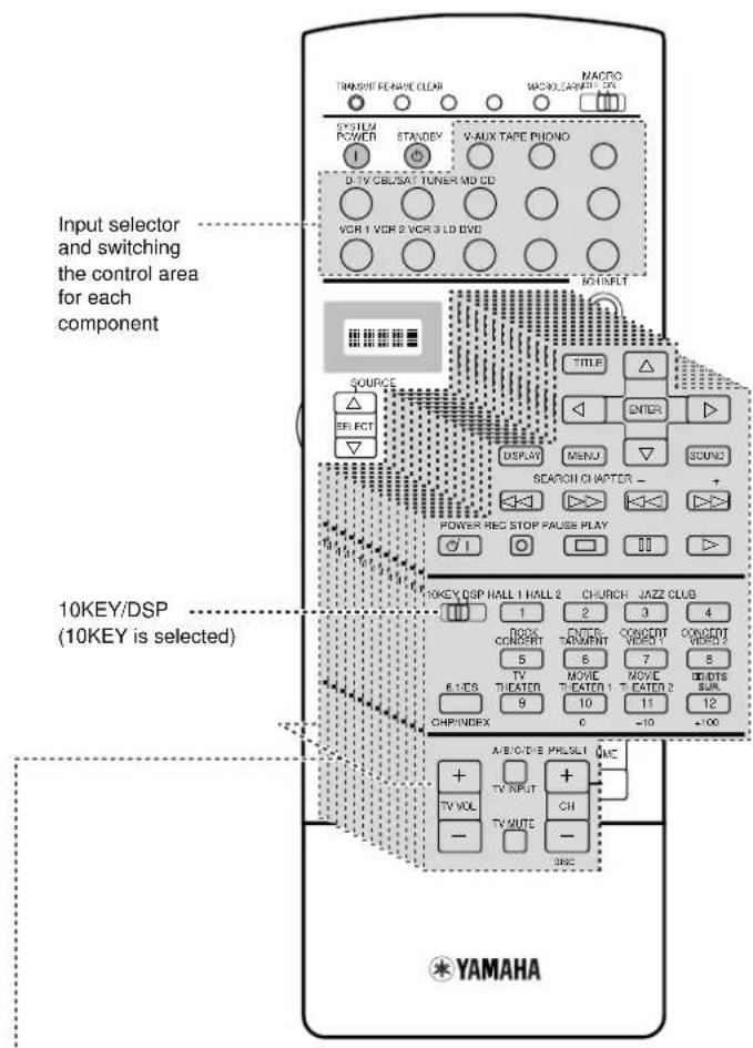
There are 14 component control areas. You can setup the manufacturer code and program other remote control functions in each area (Cannot setup the manufacturer code in the OPTN area). See pages 57 and 58.
■ SOURCE SELECT
You can control another component independently from the input you selected by pressing an input button.
1 Press SELECT △ or ▽ to choose a component and set the remote control to be used for it.
2 The display window will show one of the following: V-AUX, TAPE, PHONO, D-TV (digital and regular TV), CBSAT (Cable TV/Satellite TV), TUNER, MD, CD, VCR 1, VCR 2, VCR 3, LD, DVD, Zone2, OPTN (Option).
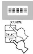
■ About Zone2
When you make up a second audio-video room with this unit's Zone2 system, you might want to use this remote control. Selecting Zone2 sets the remote control to be in the Zone2 mode. See page 65 for details.
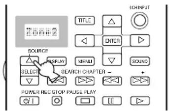
Pressing △ selects Zone2 first.
■ About OPTN
OPTN is an extra component control area to be programmed with other remote control functions. (You cannot setup the manufacturer code in this area.) See page 56 for the programmable area.
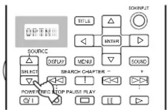
flowchart
graph TD
    A["SOURCE"] --> B["DISPLAY"]
    B --> C["MENU"]
    C --> D["SEARCH CHAPTER -"]
    D --> E["POWER-TREQ STOP PAUSE PLAY"]
    E --> F["<<|><br>    S[TITLE"] --> T["△"]
    U["ENTER"] --> V["▶"]
    W["SOUND"] --> X["▽"]
    Y["+"]
Pressing ▽ selects OPTN first.
■ Light up function
The buttons which are active and the display window light up for 10 seconds after pressing LIGHT.
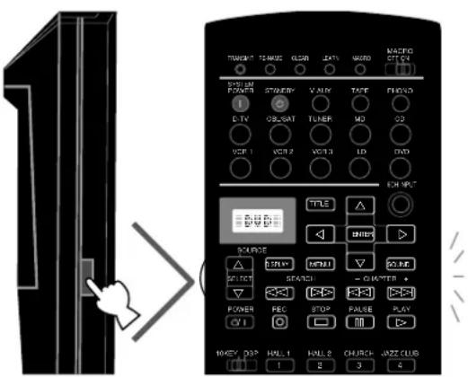
Each Component Control Area
The general operational buttons are shown for each area. Some of them may not function depending on the equipment you have.
■ Operating a Tuner (TUNER Area)
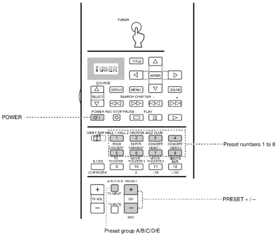
■ Operating a Tape Deck (TAPE Area)
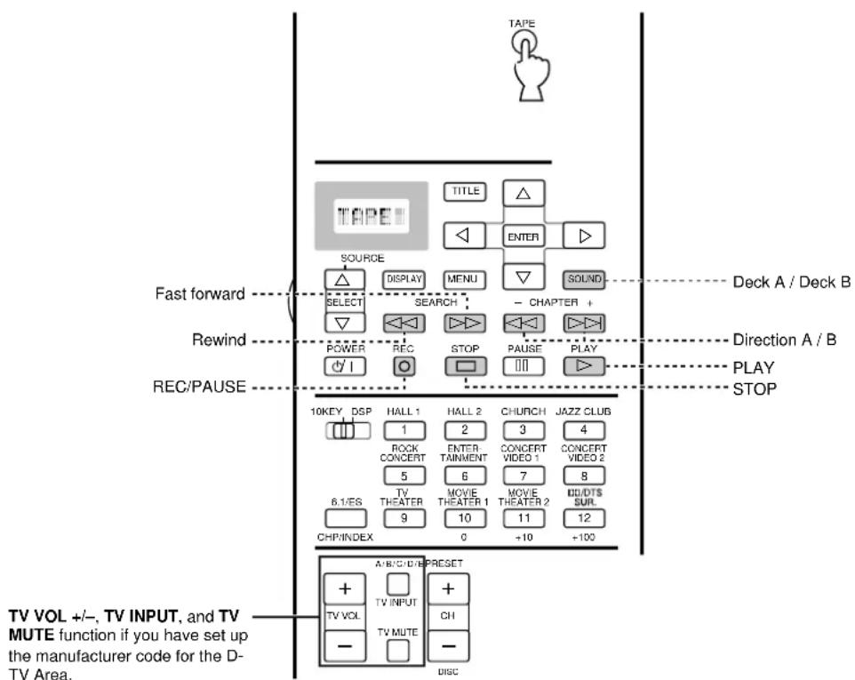
■ Operating a CD Player (CD Area)
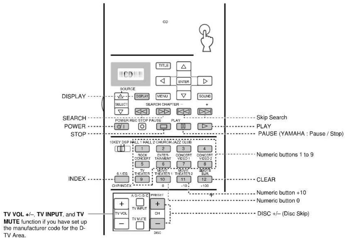
■ Operating an MD Recorder (MD Area)
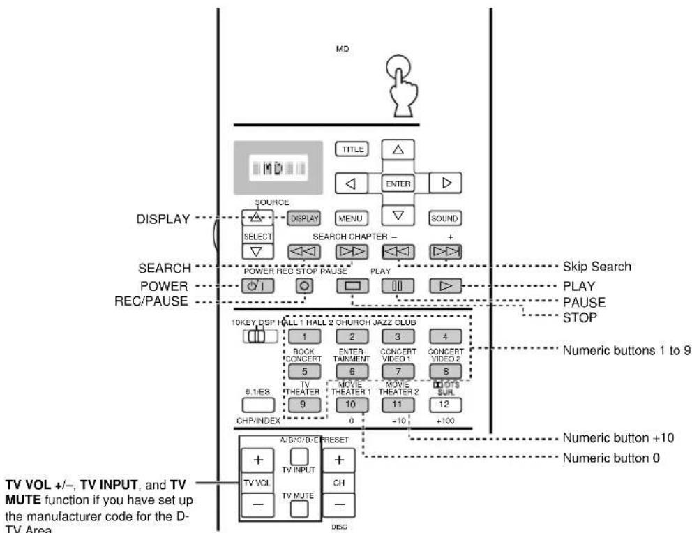
■ Operating an LD Player (LD Area)
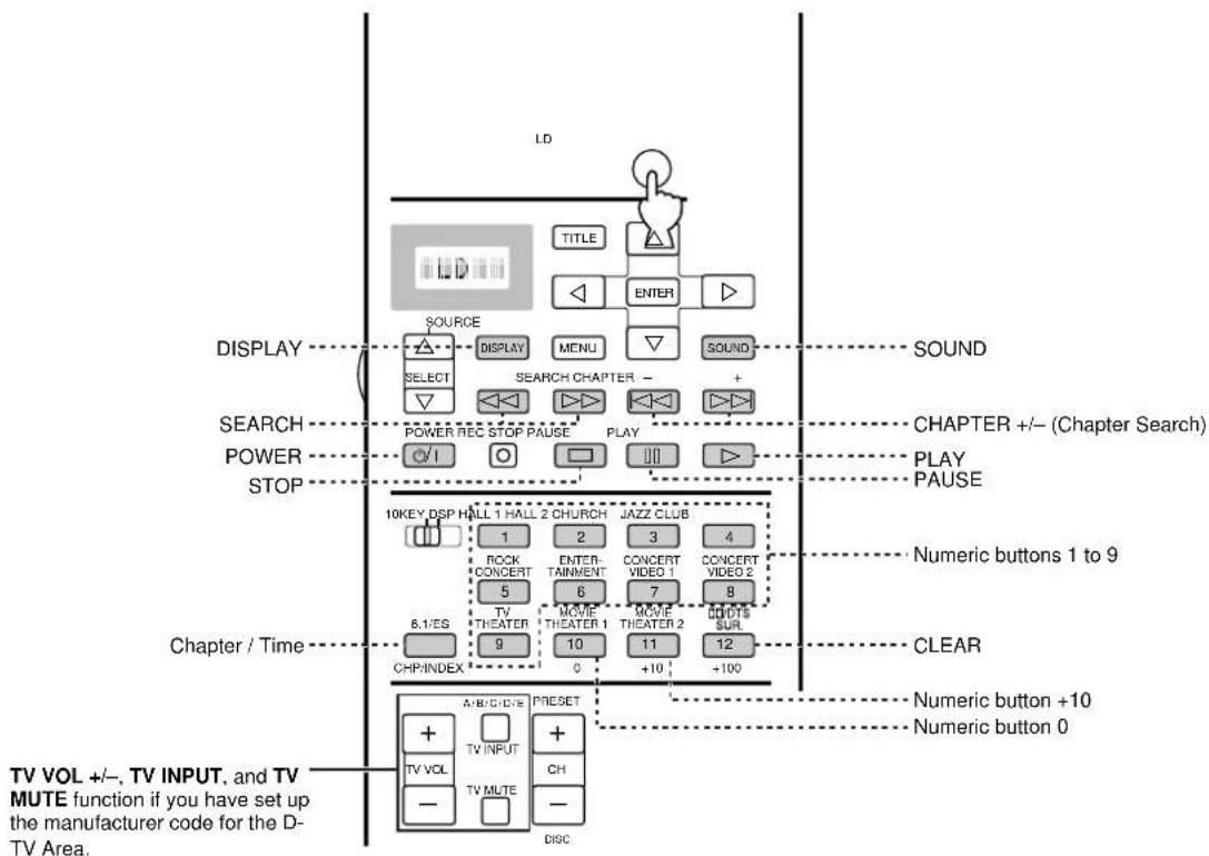
flowchart
graph TD
    A["LD"] --> B["SOURCE"]
    B --> C["DISPLAY"]
    C --> D["SELECT"]
    D --> E["POWER REC STOP PAUSE"]
    E --> F["POWER STOP"]
    F --> G["10KEY DSP HALL 1 HALL 2 CHURCH"]
    G --> H["1"]
    G --> I["2"]
    G --> J["3"]
    G --> K["4"]
    G --> L["ROCK CONCERT"]
    G --> M["ENTERTAINMENT"]
    G --> N["CONCERT VIDEO 1"]
    G --> O["CONCERT VIDEO 2"]
    G --> P["5"]
    G --> Q["6"]
    G --> R["7"]
    G --> S["8"]
    G --> T["TV THEATER"]
    G --> U["9"]
    G --> V["MOVIE THEATER 1"]
    G --> W["MOVIE THEATER 2"]
    G --> X["10"]
    G --> Y["11"]
    G --> Z["12"]
    G --> AA["CHP/INDEX"]
    AA --> AB["0"]
    AB --> AC["+10"]
    AB --> AD["+100"]
    A --> AE["SOUND"]
    A --> AF["CHAPTER +/- (Chapter Search)"]
    A --> AG["PLAY PAUSE"]
    A --> AH["Numeric buttons 1 to 9"]
    A --> AI["CLEAR"]
    A --> AJ["Numeric button +10"]
    A --> AK["Numeric button 0"]
    A --> AL["TV VOL +/-, TV INPUT, and TV MUTE function if you have set up the manufacturer code for the D-TV Area."]
■ Operating a DVD Player (DVD Area)
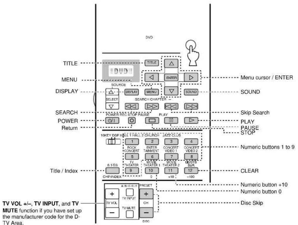
■ Operating a VCR (VCR 1 / VCR 2 / VCR 3 Area)
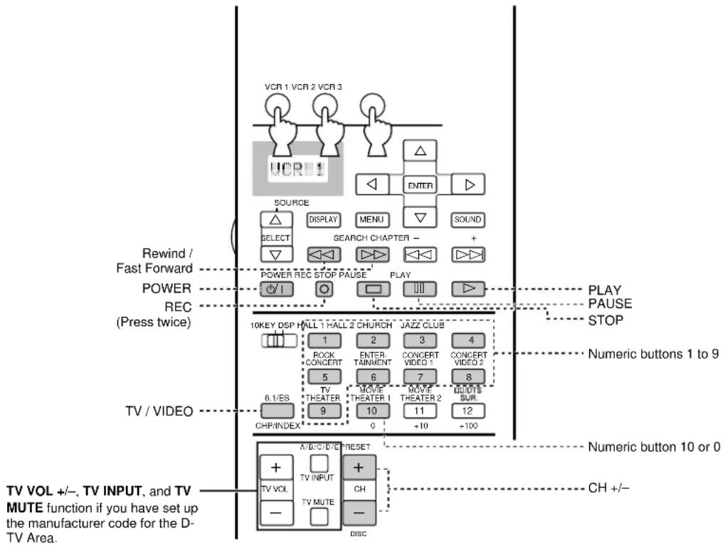
flowchart
graph TD
    A["TV VOL +/-, TV INPUT, and TV MUTE function if you have set up the manufacturer code for the D-TV Area."] --> B["TV / VIDEO"]
    B --> C["10KEY DSP HALL 1 HALL 2 CHURCH JAZZ CLUB"]
    C --> D["1"]
    C --> E["2"]
    C --> F["3"]
    C --> G["4"]
    C --> H["ROCK CONCERT ENTER TAINMENT CONCERT VIDEO 1 CONCERT VIDEO 2"]
    C --> I["5"]
    C --> J["6"]
    C --> K["7"]
    C --> L["8"]
    C --> M["6.1/ES TV THEATER MOVIE THEATER 1 MOVIE THEATER 2 BLINDTS SUR"]
    C --> N["9"]
    C --> O["10"]
    C --> P["11"]
    C --> Q["12"]
    C --> R["CHPINDEX"]
    R --> S["0"]
    R --> T["+10"]
    R --> U["+100"]
    C --> V["POWER REC STOP PAUSE PLAY"]
    V --> W["DISPLAY MENU SOUND SELECT"]
    W --> X["SOUND SEARCH CHAPTER +"]
    X --> Y["REDACT INPUT"]
    Y --> Z["REDACT STOP"]
    Z --> AA["Rewind / Fast Forward POWER REC (Press twice)"]
    AA --> AB["10KEY DSP HALL 1 HALL 2 CHURCH JAZZ CLUB"]
    AB --> AC["1"]
    AB --> AD["2"]
    AB --> AE["3"]
    AB --> AF["4"]
    AB --> AG["ROCK CONCERT ENTER TAINMENT CONCERT VIDEO 1 CONCERT VIDEO 2"]
    AB --> AH["5"]
    AB --> AI["6"]
    AB --> AJ["7"]
    AB --> AK["8"]
    AB --> AL["6.1/ES TV THEATER MOVIE THEATER 1 MOVIE THEATER 2 BLINDTS SUR"]
    AB --> AM["9"]
    AB --> AN["10"]
    AB --> AO["11"]
    AB --> AP["12"]
    AB --> AQ["CHPINDEX"]
    AQ --> AR["0"]
    AQ --> AS["+10"]
    AQ --> AT["+100"]
    AQ --> AU["AMO/C/D/E RESET"]
    AU --> AV["+"]
    AU --> AW["TV INPUT CH"]
    AU --> AX["TV MUTE - DISC"]
■ Operating a TV or Digital TV (D-TV Area)
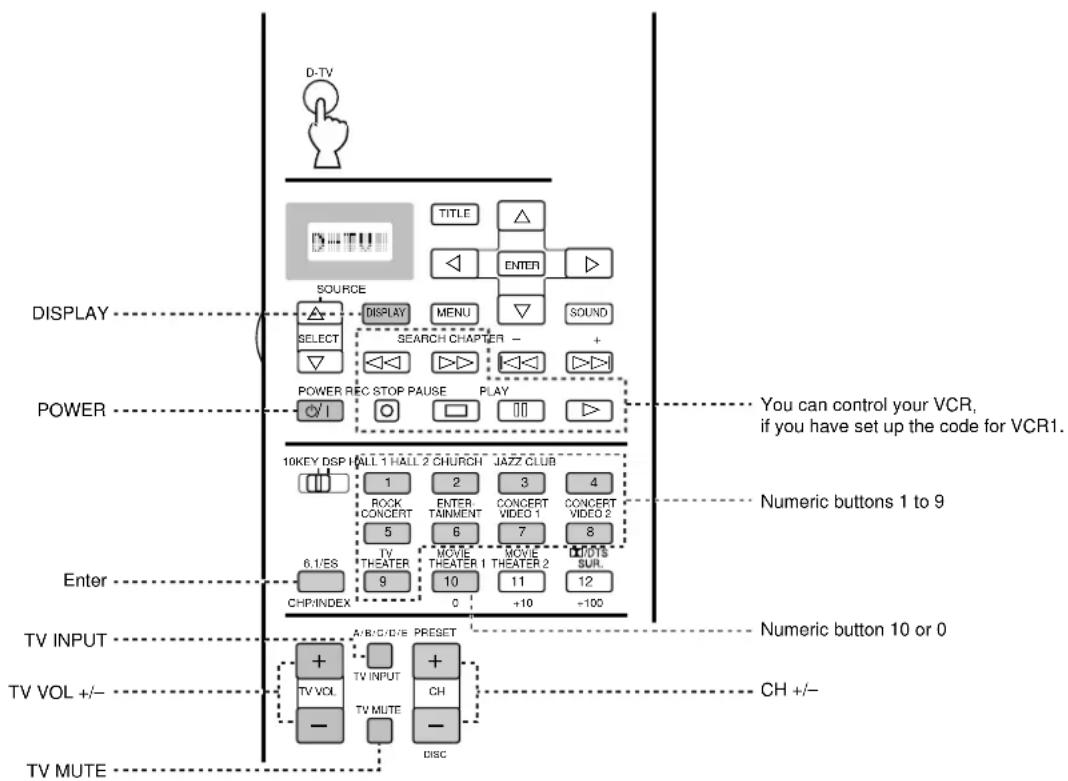
■ Operating a Cable or Satellite TV Tuner (CBSAT Area)
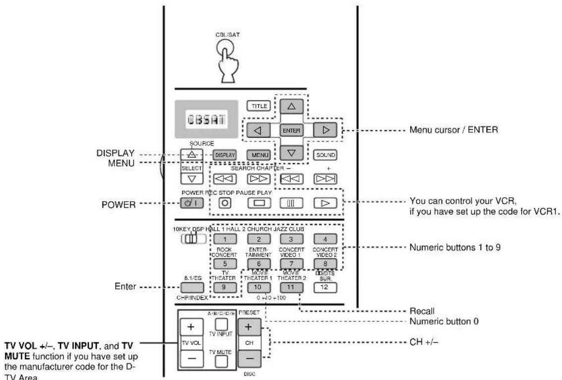
■ Free Area (OPTN and PHONO Areas)
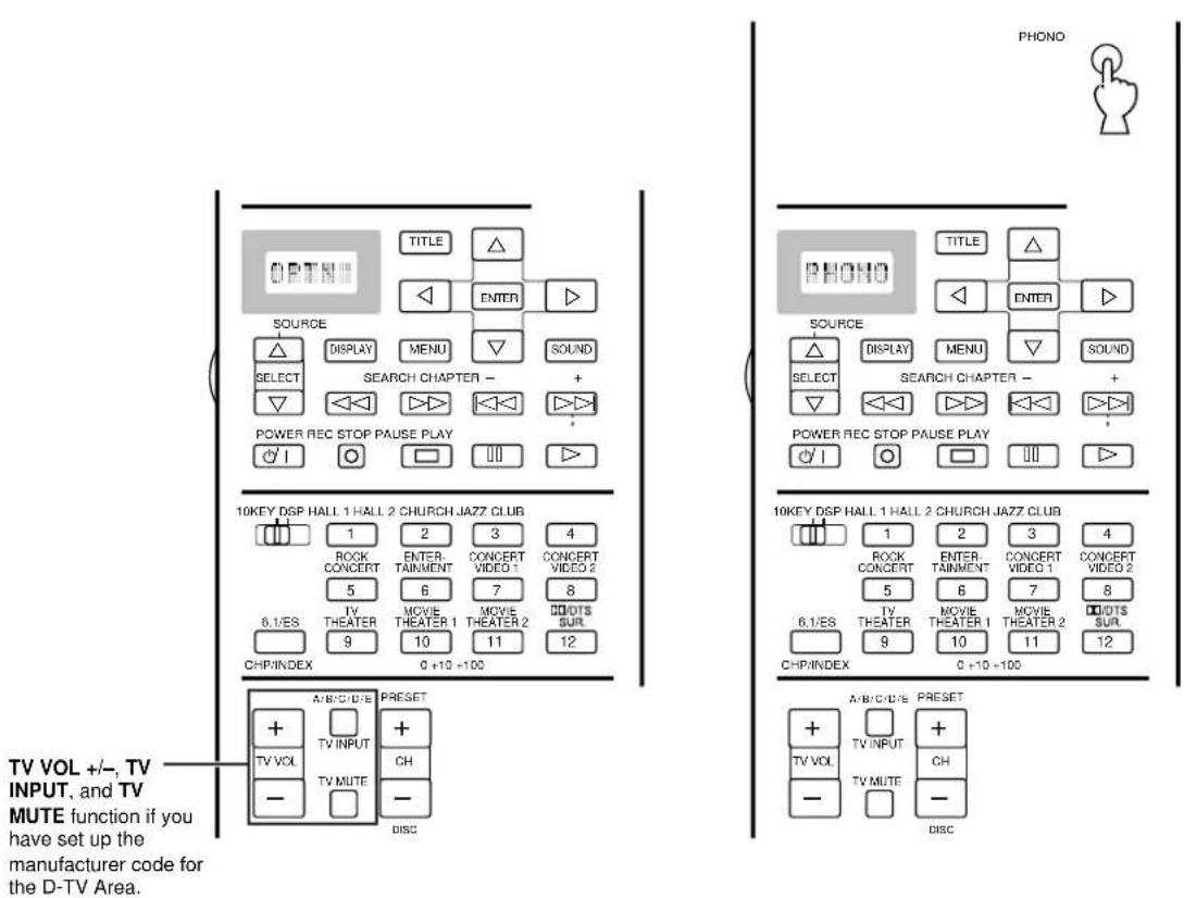
Setting the Manufacturer Code in the Remote Control
You can control other components by setting a manufacturer code. A code can be set up in each component control area except for the OPTN area. The Yamaha code is factory preset for DVD, LD, CD, MD, TUNER, and TAPE (Yamaha for LD, and Yamaha1 for others). There is no factory preset code on VCR1/2/3, D-TV, CBSAT, V-AUX, and PHONO.
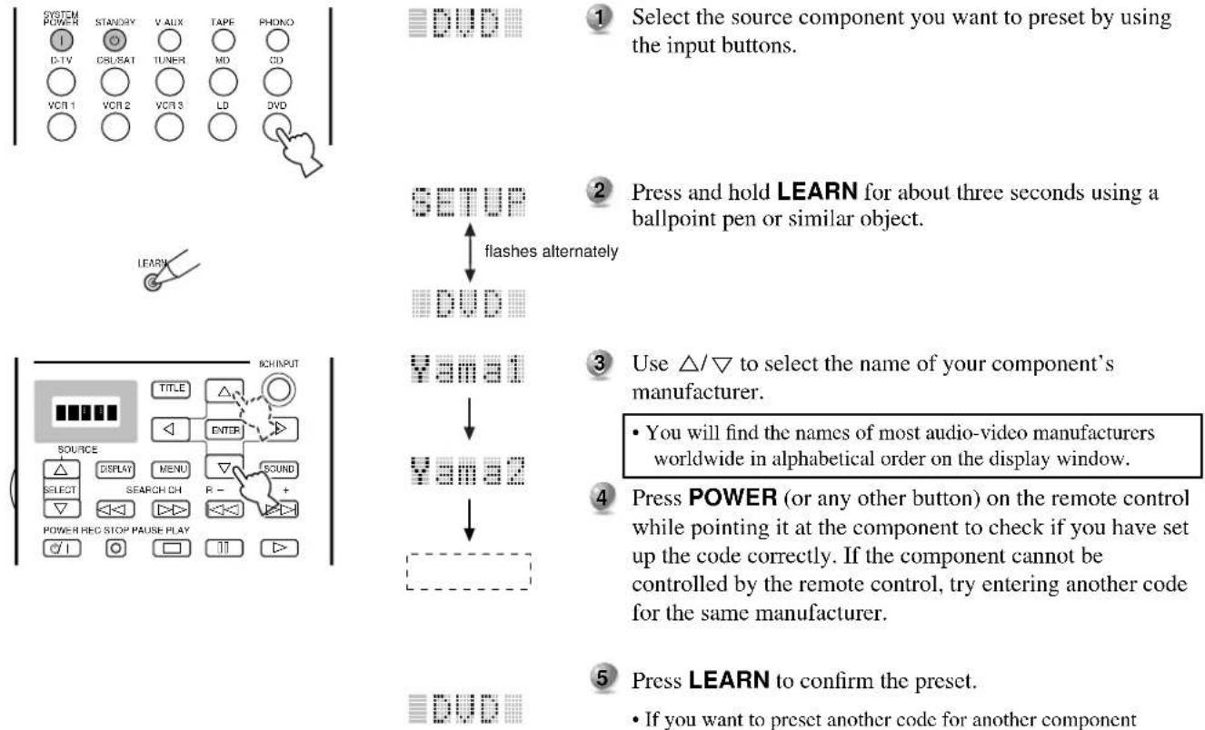
1 Select the source component you want to preset by using the input buttons.
2 Press and hold LEARN for about three seconds using a ballpoint pen or similar object.
3 Use / to select the name of your component's manufacturer.
- You will find the names of most audio-video manufacturers worldwide in alphabetical order on the display window.
4 Press POWER (or any other button) on the remote control while pointing it at the component to check if you have set up the code correctly. If the component cannot be controlled by the remote control, try entering another code for the same manufacturer.
5 Press LEARN to confirm the preset.
- If you want to preset another code for another component immediately, press ENTER and repeat steps 1 to 4.
Note:
- If you have already programmed a remote control function to a button, the function takes priority over the set up manufacturer code's function.
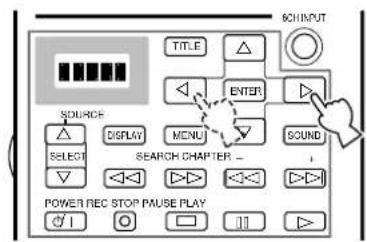
1 Repeat steps 1 and 2 of the procedure in "Setting the Manufacturer Code in the Remote Control".
2 Select a Library (component category) by using ◀/ ▷.
- There are 12 Libraries to set up a manufacturer code; L:TV, L:CAB (CABLE), L:DBS, L:SAT, L:VCR, L:DVD, L:LD, L:CD, L:MD, L:TAP (TAPE), L:TUN (TUNER), *L:AMP.
*L:AMP has three codes: YPC, DSP, and NO. "YPC" should be selected to operate the DSP-AX1. "DSP" is for operating Yamaha DSP amplifiers other than the DSP-AX1. "NO" is to clear the main unit control area functions.
3 Repeat steps 3 and 4 of the procedure in "Setting the Manufacturer Code in the Remote Control".
Note:
- "ERROR" appears in the display window in the following conditions: when pressing a button other than the cursor and ENTER; when pressing more than one button at once; and when one of MACRO ON/OFF, 10KEY/DSP, PARAMETER/SET MENU is switched to another position.
Programming a New Remote Control Function
If you desire to program functions not included in the basic operations covered by the manufacturer code, or a manufacturer code is not available, the following procedure needs to be performed. The possible programming area is the same as a component control area, so buttons are programmable independently for each source component area. It is also possible to program in the main unit control area. (Refer to page 50 for details on component control area and main unit control area.)
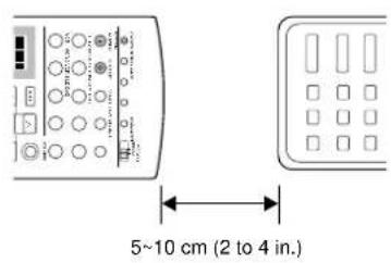

1 Place this remote control and the other remote control about 5 to 10 cm (2 to 4 in.) apart on a flat surface so that their infrared transmitters are aimed at each other.
2 Select a source component.
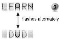
3 Press LEARN using a ball point pen or similar object.
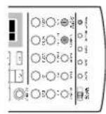
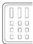
4 Press and release the button where you want the new function to be programmed.
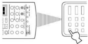

5 Press and hold the button on the other remote control that has the function you want to program into this remote control until "OK" appears in the display window.
- “NG” appears in display window when programming is not done correctly.


6 Repeat Steps 4 and 5 to program additional functions.
7 Press LEARN again to exit the Learn mode.
Notes:
- If you do not press any button within 30 seconds, the learning process is canceled.
- This remote control transmits infrared rays. If the other remote control also uses infrared rays, this remote control can learn most of the other remote control's functions. However, you may not be able to program some special signals or extremely long transmissions. (Refer to the operation instructions for the other remote control.) When the memory is full, "FULL" appears in the display window, and this remote control cannot acquire any more functions. Clear unnecessary programmed functions to allow the unit to acquire new functions.
- Even if the batteries in the other remote control have enough power to transmit signals for operation, they may not have enough power to transmit signals to this remote control.
- When the remote controls are either too close together or too far apart, you may not be able to program this remote control.
- Direct sunlight interferes with infrared rays.
- "ERROR" appears in the display window in the following conditions: when pressing more than one button at once; and when MACRO ON/OFF is switched to another position.
Remote Control Features
Using the Macro Feature
The Macro feature makes it possible to perform a series of operations by pressing just one button. For example, when you want to play a CD, normally you would turn on the components, select the CD input, and press the play button to start playback. Using the Macro feature, you can perform all those operations by simply pressing the CD macro button. The macro buttons (the input buttons and SYSTEM POWER ON/STANDBY) are factory preset with macro programs. You can also program your own macros (see page 60).
Press a Macro button Automatically transmits signals of each button sequentially
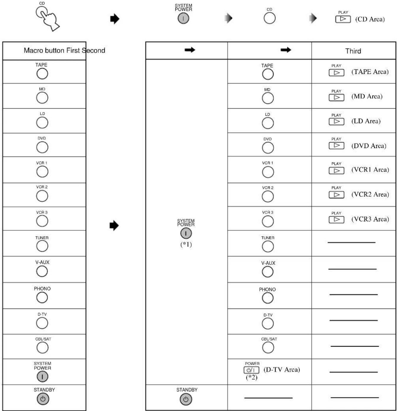
flowchart
graph LR
    A["Macro button First Second"] --> B["SYSTEM POWER"]
    B --> C["TAPE"]
    B --> D["MD"]
    B --> E["LD"]
    B --> F["DVD"]
    B --> G["VCR 1"]
    B --> H["VCR 2"]
    B --> I["VCR 3"]
    B --> J["TUNER"]
    B --> K["V-AUX"]
    B --> L["PHONO"]
    B --> M["D-TV"]
    B --> N["CBL/SAT"]
    B --> O["SYSTEM POWER"]
    B --> P["STANDBY"]

    Q["THIRD"] --> R["TAPE"]
    Q --> S["MD"]
    Q --> T["LD"]
    Q --> U["DVD"]
    Q --> V["VCR 1"]
    Q --> W["VCR 2"]
    Q --> X["VCR 3"]
    Q --> Y["TUNER"]
    Q --> Z["V-AUX"]
    Q --> AA["PHONO"]
    Q --> AB["D-TV"]
    Q --> AC["CBL/SAT"]
    Q --> AD["POWER (*2)"]
    Q --> AE["STANDBY"]

    AF["(TAPE Area)"] --> AG["PLAY (MD Area)"]
    AF --> AH["PLAY (LD Area)"]
    AF --> AI["PLAY (DVD Area)"]
    AF --> AJ["PLAY (VCR1 Area)"]
    AF --> AK["PLAY (VCR2 Area)"]
    AF --> AL["PLAY (VCR3 Area)"]

    AM["(*1)"] --> AN["THIRD"]
    AM --> AO["THIRD"]

    AP["THIRD"] --> AQ["THIRD"]
*1 In order to turn on some Yamaha components connected to this unit, connect those components to AC OUTLETS on the rear panel.
*2 If the macro you select includes power on/off functions, the equipment may turn off if it is already on when you press the macro button. For example, if your TV is on and you press the SYSTEM POWER macro button, the TV turns off.
Note:
- Make sure you set up the manufacturer code (See page 57) or program a function using the Learn feature (See page 58) to the remote control for your component, or the factory preset macros do not work.
■ Operating the Macro Feature
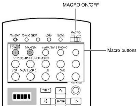
1 Set MACRO ON/OFF to ON.
2 Press a Macro button.
Notes:
- When you are finished using the Macro feature, set MACRO ON/OFF to OFF.
- While the main unit is carrying out a macro program, the main unit does not receive any other button's function until the macro is complete (the TRANSMIT indicator stops flashing).
- Continue to aim the remote control at the equipment the macro is operating until the macro program is complete.
■ Programming a Macro
You can use the Macro feature to transmit many remote control commands by pressing a single button.
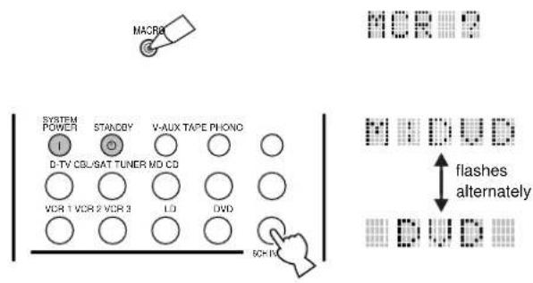
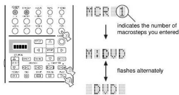

1 Press MACRO using a ball point pen or similar object.
- If you do not initiate the procedure within 30 seconds, the macro programming process is canceled.
2 Press the macro button on which you want to program the Macro.
- If you want to change the source component, use SOURCE SELECT / or the input buttons. When you use input buttons, input is selected as a Macro step, whereas SOURCE SELECT / only changes the component.
- The display window shows the button you chose for programming the macro and the component name in alternation.
3 Press the buttons of the functions that you want to include in the macro sequence in order.
- You can set up to 10 Macro steps (10 functions).
(ex)
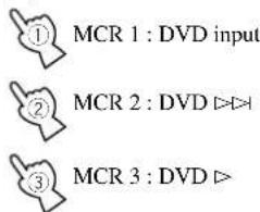
4 Press MACRO again when the sequence you want to program is complete.
• After you set 10 steps, "FULL" is displayed.
Notes:
- "NG" appears in the display window when programming is not done correctly.
- "ERROR" appears in the display window in the following conditions: when pressing more than one button at once; and when MACRO ON/OFF is switched to another position.
Changing the Source Name in the Display Window
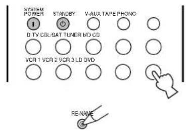

1 Select the source component you want to rename by using the input buttons.
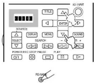

2 Press RE-NAME using a ballpoint pen or similar object.
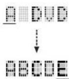
3 Use the cursor buttons / to select a character.
- Pressing changes the character in the following order: A\~Z, a\~z, 0\~9, space, -(hyphen).
4 Use the cursor buttons ◀/▷ to enter a character or more to the next cursor position.

5 Press RE-NAME to confirm renaming.
- If you want to rename another source component immediately, press ENTER and repeat steps 1, 3 and 4.
Clearing a Learned Function or Macro
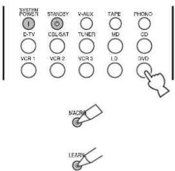

1 Select the source component that you want to clear on the window by using input buttons.
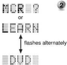
flowchart
graph TD
    A["OR"] --> B["OR"]
    C["LEARN"] --> D["DUD"]
    E["OR"] --> F["DUD"]
    G["OR"] --> H["DUD"]
    I["OR"] --> J["DUD"]
    K["OR"] --> L["DUD"]
    M["OR"] --> N["DUD"]
    O["OR"] --> P["DUD"]
    Q["OR"] --> R["DUD"]
    S["OR"] --> T["DUD"]
    U["OR"] --> V["DUD"]
    W["OR"] --> X["DUD"]
    Y["OR"] --> Z["DUD"]
    AA["OR"] --> AB["DUD"]
    AC["OR"] --> AD["DUD"]
    AE["OR"] --> AF["DUD"]
    AG["OR"] --> AH["DUD"]
    AI["OR"] --> AJ["DUD"]
    AK["OR"] --> AL["DUD"]
    AM["OR"] --> AN["DUD"]
    AO["OR"] --> AP["DUD"]
    AQ["OR"] --> AR["DUD"]
    AS["OR"] --> AT["DUD"]
    AU["OR"] --> AV["DUD"]
    AW["OR"] --> AX["DUD"]
    AY["OR"] --> AZ["DUD"]
    BA["OR"] --> BB["DUD"]
    BC["OR"] --> BD["DUD"]
    BE["OR"] --> BF["DUD"]
    BG["OR"] --> BH["DUD"]
    BI["OR"] --> BJ["DUD"]
    BK["OR"] --> BL["DUD"]
    BM["OR"] --> BN["DUD"]
    BO["OR"] --> BP["DUD"]
    BZ["OR"] --> CA["DUD"]
    CB["OR"] --> CC["DUD"]
    DD["OR"] --> DE["DUD"]
    EF["OR"] --> GF["DUD"]
    GH["OR"] --> IG["DUD"]
    IJ["OR"] --> JI["DUD"]
    AJ["OR"] --> AK["AND"]
    AL["OR"] --> AM["AND"]
    AN["OR"] --> AU["AND"]
    AO["OR"] --> AV["AND"]
    AP["OR"] --> AZ["AND"]
    AQ["OR"] --> BA
    AR["OR"] --> BB
    AS["OR"] --> BT["AND"]
    AU --> BF
    AV --> BG
2 Press LEARN if you want to clear a learned function, or press MACRO to clear a programmed macro, using a ball point pen or similar object.
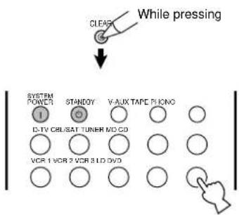
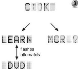
flowchart
graph TD
    A["CIOK"] --> B["LEARN"]
    A --> C["MCRP"]
    B --> D["DUD"]
    C --> E["flashes alternately"]
3 Press and hold CLEAR using a ball point pen or similar object, and at the same time press the button from which you want to clear the learned function or macro for about 3 seconds.
- “C:NG” appears in the display window if the operation is unsuccessful. Should this occur, try doing step 3 again.
You can clear other learned functions and macros at this time by continuing to hold down CLEAR and pressing the other buttons on which those learned functions or macros are programmed.

4 Press LEARN again to confirm clearing a learned function, or press MACRO again to confirm clearing a programmed macro.
- Once you clear a learned function or macro from a button, the button reverts to its factory preset function or macro.
Clearing Learned Functions, Macros, Renamed Displays, and Manufacturer Setups

1 Press CLEAR using a ballpoint pen or similar object.
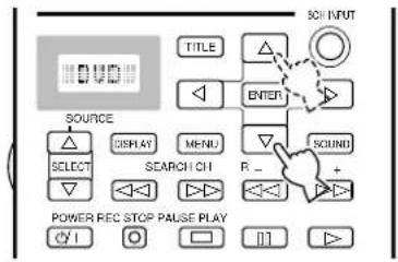
For example, when DVD is selected as the source component.
2 Press / to select the clear mode. The mode is shown in the window in the following order:
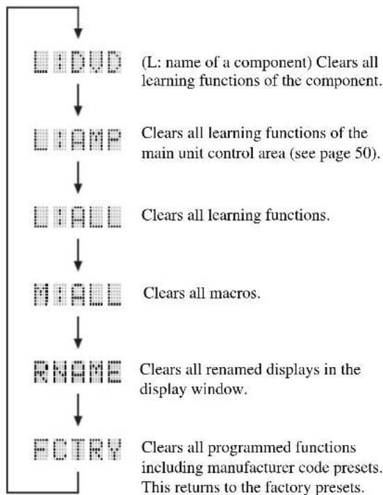
flowchart
graph TD
    A["□DVD"] --> B["□LAMP"]
    B --> C["□HALL"]
    C --> D["□MALL"]
    D --> E["□RNAME"]
    E --> F["□FTRY"]
    A --> G["(L: name of a component) Clears all learning functions of the component."]
    B --> H["Clears all learning functions of the main unit control area (see page 50)."]
    C --> I["Clears all learning functions."]
    D --> J["Clears all macros."]
    E --> K["Clears all renamed displays in the display window."]
    F --> L["Clears all programmed functions including manufacturer code presets. This returns to the factory presets."]
(L: name of a component) Clears all learning functions of the component.
Clears all learning functions of the main unit control area (see page 50).
Clears all learning functions.
Clears all macros.
Clears all renamed displays in the display window.
Clears all programmed functions including manufacturer code presets. This returns to the factory presets.

3 Press and hold CLEAR again for about 3 seconds.
- "C:NG" appears in the display window if the operation is unsuccessful.

4 Press CLEAR to confirm clearing.
- Once you clear a learned function or macro from a button, the button reverts to its factory preset function or macro.
Notes:
- If the remote control is without batteries for more than twenty minutes, or if worn out batteries remain in the unit, the contents of the memory may be cleared.
When the memory is cleared, insert new batteries and program any acquired functions that may have been cleared.
- "ERROR" appears in the display window for the following conditions: when pressing a button other than the cursor and ENTER; when pressing more than one button at once; and when one of MACRO ON/OFF, 10KEY/DSP, PARAMETER/SET MENU is switched to another position.
Adjusting the Levels of the Effect Speakers
You can adjust the volume level of each effect speaker (Center, Right Rear, Rear Center, Left Rear, Front Effect, and Subwoofer) while listening to a music source.
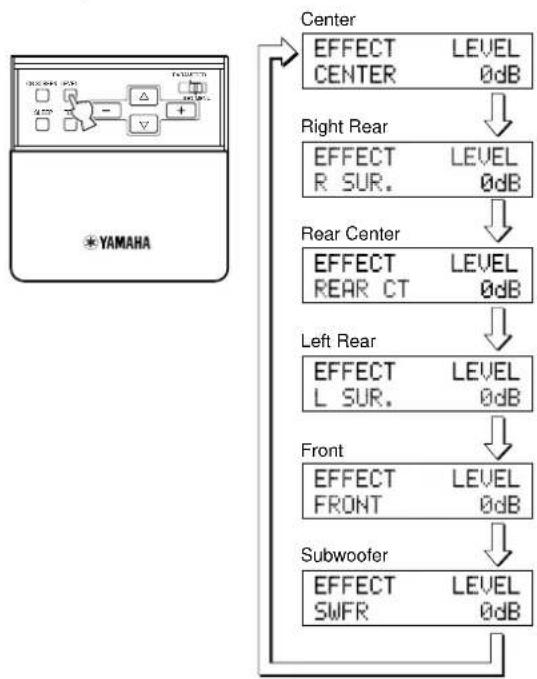
flowchart
graph TD
    A["YAMAHA"] --> B["Center"]
    B --> C["EFFECT LEVEL CENTER 0dB"]
    C --> D["Right Rear"]
    D --> E["EFFECT LEVEL R SUR. 0dB"]
    E --> F["Rear Center"]
    F --> G["EFFECT LEVEL REAR CT 0dB"]
    G --> H["Left Rear"]
    H --> I["EFFECT LEVEL L SUR. 0dB"]
    I --> J["Front"]
    J --> K["EFFECT LEVEL FRONT 0dB"]
    K --> L["Subwoofer"]
    L --> M["EFFECT LEVEL SWFR 0dB"]
1 Set PARAMETER/SET MENU to PARAMETER.
2 Press LEVEL to select the speaker(s) you want to adjust.
Each time you press this button the selected speaker changes and appears in the front panel display only as follows: Center, Right Rear, Rear Center, Left Rear, Front Effect Speakers, and Subwoofer
3 Adjust the speaker volume level using the + or - on the remote control.
You can adjust the Center, Right Rear, Rear Center, Left Rear, Front Effect Speakers from +10 dB to -10 dB.
You can adjust the Subwoofer from 0 dB down to -20 dB.
Notes:
- You cannot adjust the left and right speakers independently.
- When you adjust the speaker level using LEVEL, the settings you made using the Dolby Surround Test and DSP Test change.
- When PARAMETER/SET MENU is set to SET MENU, you cannot adjust the speaker level using LEVEL. However, each time you press LEVEL the current level setting of each speaker appears. Select the speaker level you want to check using △ or ▽.
Setting the Sleep Timer
Use this feature to automatically turn off the main unit after the amount of time you set. The Sleep Timer is useful when you plan to fall asleep while the main unit is reproducing or recording a source. The Sleep Timer also automatically turns off external components connected to AC OUTLETS. The Sleep Timer can only be set using the remote control.
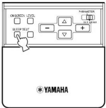
■ To set the Sleep Timer
1 Select a source using INPUT SELECTOR and start playback (or select a broadcast station) on the source component.
2 Press SLEEP repeatedly to set the amount of time before the main unit automatically turns off.
Each time you press SLEEP, the front panel display changes as shown below. After a few seconds the display returns to the previous indication.
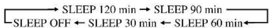
■ To cancel the Sleep Timer
1 Press SLEEP repeatedly until "SLEEP OFF" appears in the front panel display.
After a few seconds, the display returns to the previous indication.
Note:
- The Sleep Timer setting can also be canceled by turning off the main unit using STANDBY on the remote control (or STANDBY/ON on the front panel) or disconnecting the AC Power Cord from the AC outlet.
ZONE 2
You can make up a multi-room audio-video system with this unit. With this feature, you can set this unit to reproduce separate input sources in the main room and second (Zone 2) room using the supplied remote control in the second room.
Connections
To use the multi-room functions of this unit, you need the following additional equipment:
- An infrared signal receiver in the second room
- An infrared emitter in the main room
This emitter transmits the infrared signals from the remote control in the second room to the main room
(for example, to a CD player or LD player).
- An amplifier and speakers for the second room
• A video monitor for the second room
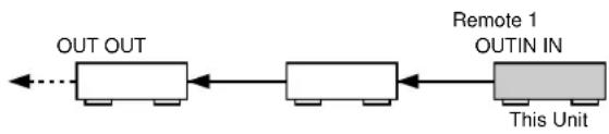
flowchart
graph LR
    A["OUT OUT"] --> B["Next Step"]
    B --> C["Remote 1 OUTIN IN"]
    C --> D["This Unit"]
    style A fill:#f9f,stroke:#333
    style B fill:#ccf,stroke:#333
    style C fill:#cfc,stroke:#333
    style D fill:#fcc,stroke:#333
Notes:
- Since there are so many ways to connect and use this unit in a multi-room installation, we recommend that you consult with a custom installation specialist for the Zone 2 connections which will best meet your requirements.
- Some Yamaha models are able to connect directly to the REMOTE 1 OUT jacks of this unit. If you own these products, you may not need to use an infrared emitter. Up to six Yamaha components can be connected as shown.
■ A sample of system configuration and connections
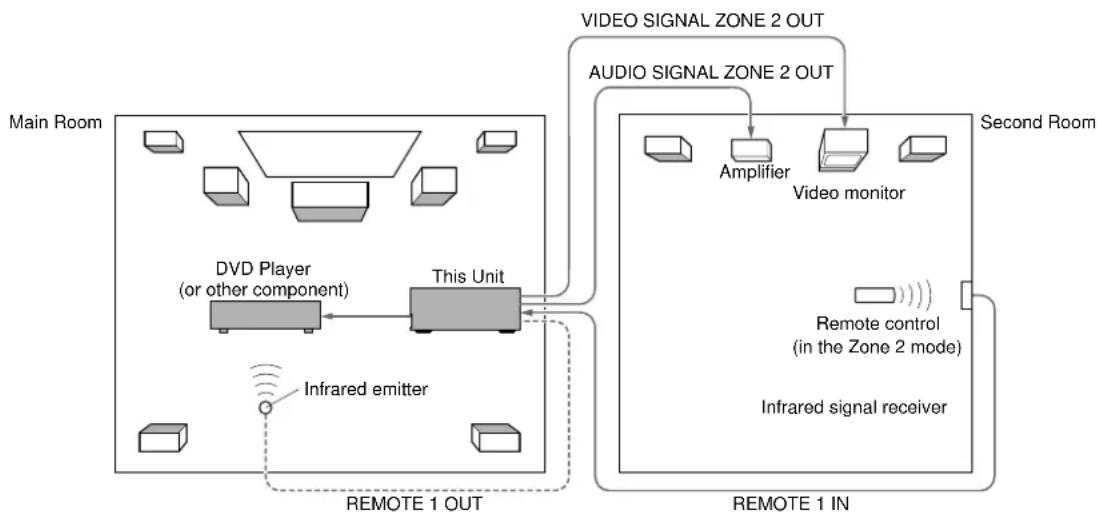
flowchart
graph TD
    A["Main Room"] --> B["This Unit"]
    B --> C["Video Signal Zone 2 OUT"]
    B --> D["Audio Signal Zone 2 OUT"]
    B --> E["Video monitor"]
    B --> F["Infrared emission"]
    B --> G["Remote control (in the Zone 2 mode)"]
    B --> H["Infrared signal receiver"]
    B --> I["Remote 1 IN"]
    J["DVD Player (or other component)"] --> B
    K["Amplifier"] --> B
    L["Second Room"] --> B
■ Special considerations when using DTS software
The DTS signal is a digital bitstream. Therefore, if you attempt to send the DTS signal to Zone 2, you will only be able to hear the digital noise that could damage your loudspeakers.
Due to this characteristic of DTS encoded discs, the following considerations and adjustments need to be made.
For DTS encoded LDs or DVDs
Only 2-channel audio signals may be sent to Zone 2, as follows:
- Laser disc – Set your Laser Disc player's left and right outputs to the analog sound track.
- DVD disc – Use the disc menu to set the DVD player's mixed 2-channel left and right audio outputs to PCM or Dolby Digital.
For DTS encoded compact discs
DO NOT USE the Zone 2 feature with DTS encoded compact discs.
Remote Control in ZONE 2
In the second (Zone 2) room, the supplied remote control can be used as the Zone 2 remote control. You can select the input source and control the component which is located in the main room directly from the second room regardless of the listening condition in the main room.
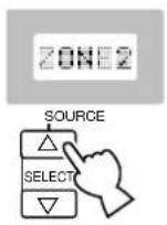
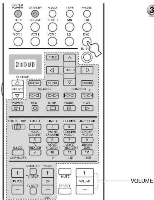
1 Press SOURCE SELECT △ to display ZONE2 in the display window.
2 Use the input buttons to select the input source you want to listen to.
- The display window shows "2: name of selected input" if the remote control is in the Zone 2 mode.
3 You can control the component using the Component Control Area buttons.
Note:
- VOLUME + / - can be used to adjust the volume if you set the SET MENU item 18. ZONE2 SET, ZONE2 OUT to "VAR." (see page 49).
Digital Sound Field Processing (DSP) 67
Understanding Sound Fields 67
Recreating a Sound Field 67
E/R (Early Reflection) 67
4ch REV. (Four Channel Reverberation) 67
Illustration of the Virtual Sound Sources and Echo Patterns.... 67
Hi-Fi DSP-Sound Field Program 68
Program Group 1 : Concert Hall 1 ....68
Program Group 2 : Concert Hall 2 68
Program Group 3 : Church 68
Program Group 4 : Jazz Club 68
Program Group 5 : Rock Concert 68
Program Group 6 : Entertainment 68
CINEMA-DSP 69
The Sound Design of CINEMA-DSP Sound Field Programs 69
Sound Field Images of the CINEMA-DSP Programs.... 69
Movie Theater Programs 70
CINEMA-DSP Sound Field Program 71
Program Group 7 : Concert Video 1 72
Program Group 8 : Concert Video 2 72
Program Group 9 : TV Theater 72
Program Group 10: Movie Theater 1 72
Program Group 11: Movie Theater 2 72
Program Group 12 : Dolby/DTS Surround 72
Sound Field Program Parameter Editing 73
Changing Parameter Settings 73
Resetting a Parameter to the Factory Preset Value 73
Digital Sound Field Parameter Descriptions 74
EFCT TRIM (Effect Trim) 74
INIT. DLY (Initial Delay) 74
P. INIT. DLY (Presence Initial Delay) 74
RC. INIT. DLY (Rear Center Initial Delay) 74
S. INIT. DLY (Surround Initial Delay) 74
S. DLY (Surround Delay) 75
ROOM SIZE 75
RC. ROOM SIZE (Rear Center Room Size) 76
S. ROOM SIZE (Surround Room Size).... 76
LIVENESS 76
S. LIVENESS(Surround Liveness) 76
RC LIVENESS (Rear Center Liveness) 76
REV. TIME (Reverberation Time) 77
REV. DELAY (Reverberation Delay) 77
REV. LEVEL (Reverberation Level) 77
Understanding Sound Fields
A sound field is defined as the “characteristic sound reflections of a particular space.” In concert halls and other music venues, we hear early reflections and reverberations as well as the direct sound produced by the artist(s). The variations in the early reflections and other reverberations among the different music venues is what gives each venue its special and recognizable sound quality.
Yamaha sent teams of sound engineers all around the world to measure the sound reflections of famous concert halls and music venues, and collect detailed sound field information such as the direction, strength, range, and delay time of those reflections. Then we stored this enormous amount of data in the ROM chips of the DSP-AX1.
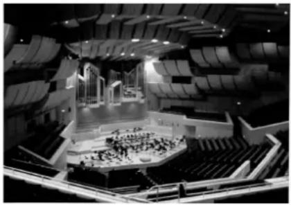
natural_image
Interior view of a modern auditorium with tiered seating and central stage (no visible text or symbols)
Recreating a Sound Field
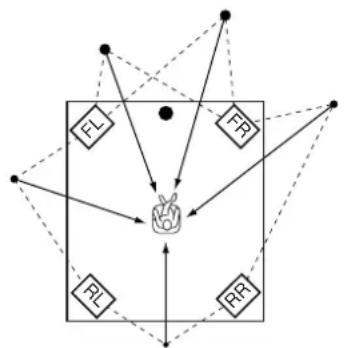
flowchart
graph TD
    A["FL"] --> B["Object"]
    C["FR"] --> B
    D["PL"] --> B
    E["RR"] --> B
    B --> F["Central Object"]
    style A fill:#f9f,stroke:#333
    style C fill:#f9f,stroke:#333
    style D fill:#f9f,stroke:#333
    style E fill:#f9f,stroke:#333
    style F fill:#ccf,stroke:#333
Recreating the sound field of a concert hall or an opera house requires localizing the virtual sound sources in your listening room. The traditional stereo system that uses only two speakers is not capable of recreating a realistic sound field.
Yamaha's DSP requires four effect speakers to recreate sound fields based on the measured sound field data. The processor controls the strength and delay time of the signals output from the four effect speakers to localize the virtual sound sources in a full circle around the listener.
The DSP sound field programs can be classified in two types based on the sound field processing method: programs that use early reflections only and programs that use both early reflections and reverberation.
E/R (Early Reflection)
Each sound field is distinguished by the structure of the reflected sound. The increased processing capability of DSP technology enables Yamaha engineers to incorporate even minute reflections with long delay times into the sound field data.
4ch REV. (Four Channel Reverberation)
This type of program consists of early reflections and high quality digital reverberation processing. Reverberation is the most important element for recreating the sound field of a church. To recreate a realistic spatial sound image from reverberation data, Yamaha has adapted the four-channel-output reverberation technology.
Illustration of the Virtual Sound Sources and Echo Patterns
The virtual sound sources and echo patterns for the DSP sound field programs are shown below. The illustration of the virtual sound sources shows early reflection sound only and the illustration of the echo patterns shows both reflected sound and reverberation.
Virtual Sound Sources
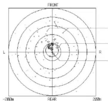
The center of these circles represent the virtual sound source.
The size of the circle indicates the strength of the virtual sound source.
The direct sound source
The listening position
Echo Patterns
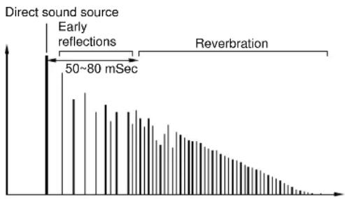
bar
| Time Interval | Value |
| ------------- | ----- |
| Early reflections | 50~80 mSec |
| Reverberation | - |
Program Group 1 : Concert Hall 1
■ Europe Hall A
This is a large fan-shaped concert hall in Munich which has approximately 2500 seats. Almost the whole interior is made of wood. There is relatively little reflection from the walls, and sound spreads finely and beautifully.
■ Europe Hall B
This is a large shoe-box type concert hall with less than 2400 seats located in Frankfurt. This hall has a very solid, powerful sound. The listener's virtual seat is in the center-right section on the first floor.
■ Europe Hall C
A classic shoe-box type concert hall with approximately 1700 seats. Pillars and ornate carvings create extremely complex reflections which produce a very full, rich sound.
Program Group 2 : Concert Hall 2
■ U.S.A. Hall D
This is a large 2600 seat concert hall in the United States which features a fairly traditional European design. The interior is relatively simple, in the American style. The middle and high frequencies are richly and beautifully reinforced.
■ Europe Hall E
This is a large 2200 seat shoe-box type concert hall in Amsterdam. It has a circular stage with seats located behind the stage.
■ Live Concert
A large round concert hall with a rich surround effect. Pronounced reflections from all directions emphasize the extension of sounds. The sound field has a great deal of presence, and your virtual seat is near the center, close to the stage.
Program Group 3 : Church
■ Tokyo
The acoustic environment of an ordinary church with moderate reverberations. The reverberation lasts 2.5 seconds. This is ideal for reproducing church organ and choral music.
■ Freiburg
This program recreates the acoustic environment of a big church located in south Germany. The reverberation delay is very long while the early reflections are smaller than with other sound field programs.
■ Royaumont
This program features the sound field created by the refectory (dining hall) of a beautiful medieval Gothic monastery located in Royaumont on the outskirts of Paris.
Program Group 4 : Jazz Club
■ Village Gate
This is the sound field at a jazz club in New York. It is in a basement and has a relatively spacious floor area. The listener's virtual seat is at the center left of the hall.
■ Village Vanguard
A traditional jazz club in New York, located on 7th Avenue. This room has a low ceiling, and the “stage” is located in a corner. This program creates an intimate “close-to-the music” feel.
■ The Bottom Line
This is the sound field at stage front in "The Bottom Line", a famous New York jazz club. The floor can seat 300 people to the left and right in a sound field offering a real and vibrant sound.
Program Group 5 : Rock Concert
■ Roxy Theatre
The ideal program for lively, dynamic rock music. The data for this program was recorded at LA's "hottest" rock club. The listener's virtual seat is at the center-left of the hall.
■ Warehouse Loft
This program simulates a space enclosed by concrete. An energetic sound field is created with relatively clear reflections from the walls.
■ Arena
A classic shoe-box type concert hall. This program gives you long delays between direct sounds and effect sounds, with the extraordinarily spacious feel of a large arena.
Program Group 6 : Entertainment
■ Disco
This program recreates the acoustic environment of a lively disco in the heart of a big city. The sound is dense and highly concentrated. It is also characterized by a high-energy, "immediate" sound.
■ Party
This is a sound field suitable for background music at parties where you can hear the sound directly from the rear as well, thus realizing music enjoyment over a wide area.
■ Game/Amusement
This program adds a deep and spatial feeling to video game sounds and is also suitable for karaoke.
The Sound Design of CINEMA-DSP Sound Field Programs
Filmmakers intend the dialog to be located right on the screen, the effect sound a little farther back, the music spread even farther back, and the surround sound around the listener. Of course, all of these sounds must be synchronized with the images on the screen.
CINEMA-DSP is an upgraded version of YAMAHA DSP specially designed for movie soundtracks. CINEMA-DSP integrates the DTS, Dolby Digital, and Dolby Pro Logic surround sound technologies with YAMAHA DSP sound field programs to provide the surround sound field. It recreates the most complete movie sound design in your audio room. In CINEMA-DSP sound field programs, Yamaha's exclusive DSP processing is added to the front left, center, and right channels, so the listener can enjoy realistic dialogue, depth of sound, smooth transition between sound sources, and a surround sound field that goes beyond the screen.
When a DTS or Dolby Digital signal is detected, the CINEMA-DSP sound field processor automatically chooses the most suitable sound field program for that signal.
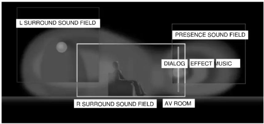
Sound Field Images of the CINEMA-DSP Programs
Each CINEMA-DSP program has its own type of sound field processing block. The sound field data, including the presence and surround sound fields, are based on actual measured data. The presence and surround sound fields can be expressed in the distribution of virtual sound sources and echo patterns. However, as these two types of sound fields are processed with complex elements such as energy balance and mixing signal ratios, they are expressed as a sound field based on auditory perception.
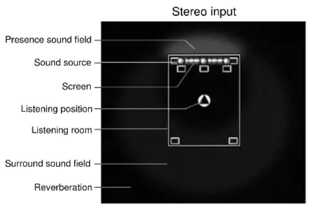
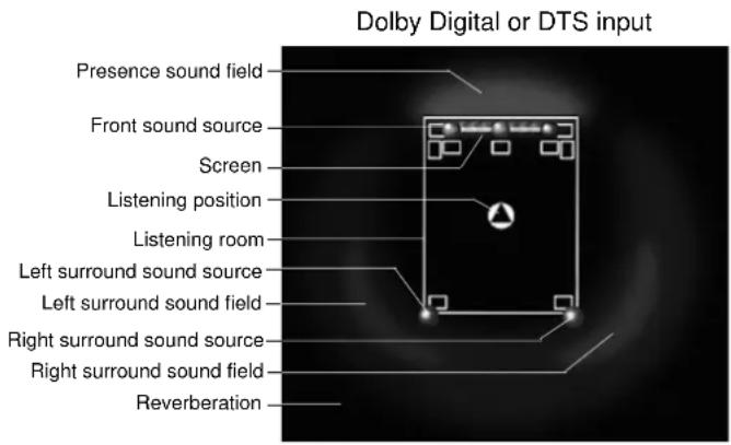
Movie Theater Programs
Most movie software has four-channel (left, center, right and surround) sound information encoded using Dolby Surround matrix processing and stored on the left and right tracks. These signals are processed by the Dolby Pro Logic decoder. The Movie Theater Programs are designed to recreate the spaciousness and delicate nuances of sound that tend to be lost in the encoding and decoding processes. The six-channel soundtracks found on 70 mm film produce precise sound field localization and rich, deep sound without using matrix processing. The DSP-AX1's Movie Theater 70 mm Programs provide the same quality of sound and sound localization that six-channel soundtracks do. The built-in Dolby Digital decoder brings the professional quality sound designed for movie theaters, into your home. With the DSP-AX1's Movie Theater program, you can recreate a dynamic sound that gives you the feeling of being at a public theater in your living room using the Dolby Digital technology.
■ Dolby Pro Logic + DSP Sound Field Effect
These programs express an immense sound field and a large surround effect. They also give depth to the sound from the Main Speakers to recreate the realistic sound of a Dolby Stereo theater.
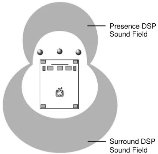
■ Dolby Digital/DTS + DSP Sound Field Effect
These programs use Yamaha's tri-field DSP process on each of the Dolby Digital signals for the front, left surround, and right surround channels. This processing enables the DSP-AX1 to reproduce the immense sound field and surround expression of a Dolby Digital equipped movie theater without sacrificing the clear separation of all channels.
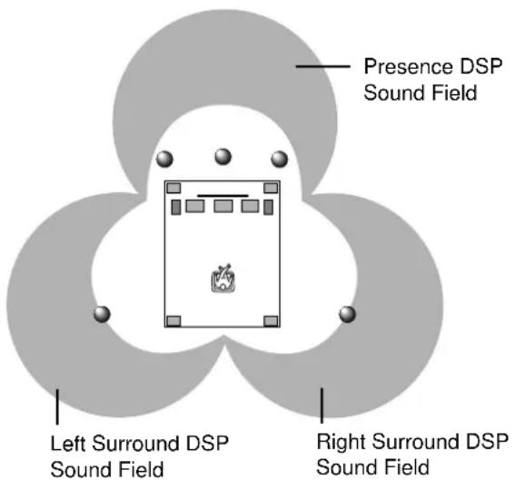
■ Dolby Digital/Matrix 6.1+ DSP Sound Field Effect or DTS ES+ DSP Sound Field Effect
These programs provide the full experience of spacious surround effects with the addition of an extra Rear Center DSP sound field created using the Rear Center channel.
According to the input signal format, the DSP-AX1 automatically chooses the appropriate decoder and DSP sound field pattern.
Table of Program Names for Each Input Format
| Program Group\Input | Stereo(2ch) | DOLBY DIGITAL(5.1ch) | DTS(5.1ch) | DOLBY DIGITAL(6.1ch)* | DTS ES(6.1ch)* |
| 7 | CONCERTVIDEO 1 | Pop/Rock | -------- | -------- | -------- | -------- |
| DJ | -------- | -------- | -------- | -------- |
| 8 | CONCERTVIDEO 2 | Classical/Opera | -------- | -------- | -------- | -------- |
| Pavilion | -------- | -------- | -------- | -------- |
| 9 | TVTHEATER | Mono Movie | -------- | -------- | -------- | -------- |
| Variety/Sports | -------- | -------- | -------- | -------- |
| 10 | MOVIE THEATER 1 | 70 mm Spectacle | DGTL Spectacle | DTS Spectacle | Spectacle 6.1 | Spectacle ES |
| 70 mm Sci-Fi | DGTL Sci-Fi | DTS Sci-Fi | Sci-Fi 6.1 | Sci-Fi ES |
| 11 | MOVIE THEATER 2 | 70 mm Adventure | DGTL Adventure | DTS Adventure | Adventure 6.1 | Adventure ES |
| 70 mm General | DGTL General | DTS General | General 6.1 | General ES |
| 12 | PRO LOGIC | Normal | -------- | -------- | -------- | -------- |
| Enhanced | -------- | -------- | -------- | -------- |
| DOLBY DIGITAL | -------- | Normal | -------- | Matrix 6.1 | -------- |
| -------- | Enhanced | -------- | Enhanced 6.1 | -------- |
| DTS DIGITAL SUR | -------- | -------- | Normal | -------- | ES |
| -------- | -------- | Enhanced | -------- | Enhanced ES |
* The Matrix decoder is ON.
■ Program Groups 7\~9
These are sound field programs for the audio-video sources.
■ Program Groups 10\~12
Ideal for reproducing a movie program which is encoded with Dolby Surround, Dolby Digital, or DTS. When the newest movie program encoded with Dolby Digital Surround EX or DTS ES is input, you can enjoy the full 6.1 channel reproduction using the internal Matrix decoder.
PRO LOGIC functions when the input signal is analog or PCM audio, or encoded with Dolby Digital in two channels.
DOLBY DIGITAL functions when the input signal is encoded with Dolby Digital in more than two channels.
DTS DIGITAL SUR functions when the input signal is encoded with DTS.
Note:
- No sound will be output from the Main speakers when a monaural source is played with sound field Program Groups 7\~12.
CINEMA-DSP Sound Field Program
Program Group 7 : Concert Video 1
■ Pop/Rock
This program produces an enthusiastic atmosphere and lets you feel as if you are at an actual jazz or rock concert.
■ DJ
The sound field makes the voice of a disc jockey sound clearer.
Program Group 8 : Concert Video 2
■ Classical/Opera
This program provides excellent vocal depth and overall clarity by restraining excessive reverberation.
The surround sound field is relatively moderate but it reproduces beautiful sound using data collected from a concert hall.
■ Pavilion
This program reproduces vocals clearly, letting you feel the spaciousness of a pavilion. Reverberation, which is somewhat delayed, reproduces the live acoustics unique to a pavilion, and helps to make concert scenes more exciting.
Program Group 9 : TV Theater
■ Mono Movie
This program is provided for reproducing monaural video sources (such as old movies). The program produces the optimum reverberation to create sound depth using only the presence sound field.
■ Variety/Sports
Though the presence sound field is relatively narrow, the surround sound field employs the sound environment of a large concert hall. With this program, you can enjoy watching various TV programs such as news, variety shows, music programs or sports programs.
Program Group 10 : Movie Theater 1
■ Spectacle
This program creates the extremely wide sound field of a 70 mm movie theater. It precisely reproduces the source sound in detail, making both the video and the sound fields incredibly real. This program is ideal for any kind of Dolby Surround video source (especially large-scale movie productions).
■ Sci-Fi
This program clearly reproduces the broad and expansive cinematic space from the soundtracks of the latest science fiction films.
Program Group 11 : Movie Theater 2
■ Adventure
This program is ideal for precisely reproducing the sound design of the newest 70 mm and multichannel soundtrack films. The sound field is made to be similar to that of the newest movie theaters, so the reverberations of the sound field itself are restrained as much as possible.
■ General
This program is for reproducing sounds from 70 mm and multichannel soundtrack films, and is characterized by a soft and extensive sound field. The presence sound field is relatively narrow. It spatially spreads all around and toward the screen, restraining the effect of conversations without losing clarity.
Program Group 12 : Dolby/DTS Surround
■ Normal/Matrix 6.1/ES
The built-in decoder precisely reproduces sounds and sound effects from sources. The highly efficient decoding process improves crosstalk and channel separation and makes sound positioning smoother and more precise.
In this program, no DSP effect is applied.
■ Enhanced/6.1/ES
This program ideally simulates the multiple surround speaker systems of 35 mm film theaters. The Dolby Surround decoding and the digital sound field processing create precise effects without altering the original sound orientation. The surround effects produced by this sound field wrap around the viewer naturally from the back to the left and right and toward the screen.
You can enjoy good quality sound with the preset parameters. Although you do not have to change the initial settings, you can change some of the parameters to better suit the input source or your listening room.
Changing Parameter Settings

1 Set PARAMETER/SET MENU to PARAMETER on the remote control.
2 Turn on your video monitor and press ON SCREEN to select the full display.
3 Select the sound field program you want to adjust.
4 Press or to select the parameter.
5 Press + or - to change the parameter value.
When you set the parameter to a value other than the factory preset value, an asterisk mark appears by the parameter name on the monitor screen.
6 Repeat steps 3 through 5 above as necessary to change other program parameters.
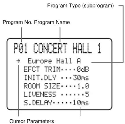
Example of the CONCERT HALL 1
Resetting a Parameter to the Factory Preset Value
■ To reset some of the parameters to the factory preset values
Select the parameter you want to reset. Then, press and hold + or - until the value stops at the factory preset value temporarily. (The asterisk mark by the parameter name disappears on the video monitor.)
■ To reset all of the parameters back to the factory preset values
Use the SET MENU to reset all of the parameter values of all DSP programs within the selected group to the factory preset values (see page 47). This operation resets all of the parameter values of all DSP programs within that group to the factory preset values.
Notes:
- The available parameters may be displayed on more than one OSD page for some of the programs. To scroll through pages, press or .
- When “MEMORY GUARD!” appears on the screen, the Memory Guard function is on, and you cannot change parameter values. Turn off the Memory Guard function using the SET MENU (see page 48).
Digital Sound Field Parameter Descriptions
You can adjust the values of certain digital sound field parameters so the sound fields are recreated accurately in your listening room. Not all of the following parameters are found in every program.
EFCT TRIM (Effect Trim)
Function ...... This parameter adjusts the level of all the effect sounds within a narrow range.
Control Range ...... -3 dB - +3 dB
Description .... Depending on the acoustics of your listening room, you may want to increase or decrease the effect level relative to the direct sound.
INIT. DLY (Initial Delay)
Function .... This parameter changes the apparent distance from the source sound by adjusting the delay between the direct sound and the first reflection heard by the listener.
Control Range ...... 1 - 99 milliseconds
Description .... The smaller the value, the closer the sound source seems to the listener. The larger the value, the farther the apparent distance seems. For a small room, this parameter would be set to a small value, for a large room, set it to a large value.
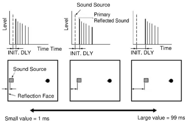
P. INIT. DLY (Presence Initial Delay)
Function ...... This parameter adjusts the delay between the direct sound and the first reflection in the presence sound field.
Control Range ...... 1 - 99 milliseconds
Description ...... The larger the value, the later the first reflection begins.
RC. INIT. DLY (Rear Center Initial Delay)
Function ...... This parameter adjusts the delay between the direct sound and the first reflection in the rear center sound field.
Control Range ...... 1 - 49 milliseconds
Description ...... The larger the value, the later the first reflection begins.
S. INIT. DLY (Surround Initial Delay)
Function .... This parameter adjusts the delay between the direct sound and the first reflection on the surround side of the sound field. You can only adjust this parameter when at least two front channels and two rear channels are used.
Control Range ...... 1 - 49 milliseconds
Description .... The larger the value, the later the first reflection begins. You can only adjust this parameter for the Dolby Digital and DTS signals.
S. DLY (Surround Delay)
Function .... This parameter adjusts the delay between the direct sound and the first reflection in the surround sound field.
Control Range ...... 0 - 49 milliseconds (The range depends on the signal format.)
Description ...... When Dolby Digital signals are decoded: the larger the parameter, the later the surround sound source begins.
When a non-Dolby Digital program is decoded: the larger the parameter, the later the surround sound field begins.
No surround sound source is produced.
Dolby Digital or DTS Input
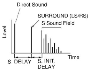
bar
| Time Segment | Level |
| ------------------ | ----- |
| Direct Sound | High |
| S Sound Field | High |
| S. INIT. DELAY | Medium|
| S. INIT. DELAY | Low |
Others
The surround sound field is not reproduced.
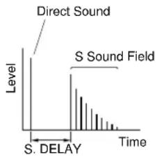
bar
| Time Segment | Level |
| ---------------- | ----- |
| Direct Sound | High |
| S Sound Field | Medium|
| S. DELAY | Low |
ROOM SIZE
Function .... This parameter adjusts the apparent size of the surround sound field. The larger the value, the larger the surround sound field becomes.
Control Range ...... 0.1 - 2.0
Description ...... As the sound is repeatedly reflected around a room, the larger the hall is, the longer the time between the original reflected sound and the subsequent reflections. By controlling the time between the reflected sounds, you can change the apparent size of the virtual venue. Changing this parameter from one to two, doubles the apparent length of the room.
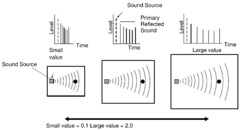
RC. ROOM SIZE (Rear Center Room Size)
Function ...... This parameter adjusts the apparent size of the rear center sound field.
Control Range ...... 0.1 - 2.0
Description .... The larger the value, the more reflective the presence sound field walls become.
S. ROOM SIZE (Surround Room Size)
Function ...... This parameter adjusts the apparent size of the surround sound field.
Control Range ...... 0.1 - 2.0
Description .... The larger the value, the larger the surround sound field becomes.
LIVENESS
Function .... This parameter adjusts the reflectivity of the virtual walls in the hall by changing the rate at which the early reflections decay.
Control Range ...... 0 - 10
Description .... The early reflections of a sound source decay much faster in a room with acoustically absorbent wall surfaces than in one which has highly reflective surfaces. A room with acoustically absorbent surfaces is referred to as “dead,” while a room with highly reflective surfaces is referred to as “live.” The LIVENESS parameter lets you adjust the early reflection decay rate, and thus the “liveness” of the room.
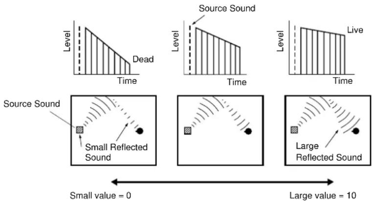
S. LIVENESS (Surround Liveness)
Function .... This parameter adjusts the apparent reflectivity of the virtual walls in the surround sound field.
Control Range ...... 0 - 10
Description ...... The larger the value, the more reflective the surround sound field walls become.
RC. LIVENESS (Rear Center Liveness)
Function ...... This parameter adjusts the apparent reflectivity of the virtual wall in the rear center sound field.
Control Range ...... 0 - 10
Description ...... The larger the value, the more reflective the surround sound field walls become.
REV. TIME (Reverberation Time)
Function .... This parameter adjusts the amount of time it takes for the dense, subsequent reverberation sound to decay by 60 dB (at 1 kHz). This changes the apparent size of the acoustic environment over an extremely wide range.
Control Range ..... 1.0 - 5.0 seconds
Description .... Set a longer reverberation time for "dead" sources and listening room environments and a shorter time for "live" sources and listening room environments.
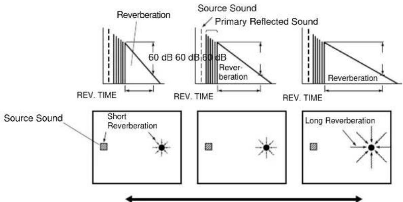
Small value = 1.0 s Large value = 5.0 s
REV. DELAY (Reverberation Delay)
Function .... This parameter adjusts the time difference between the beginning of the direct sound and the beginning of the reverberation sound.
Control Range ..... 0 - 250 milliseconds
Description .... The larger the value, the later the reverberation sound begins. A later reverberation sound makes you feel like you are in a larger acoustic environment.
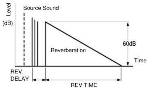
line
| Level (dB) | Time (dB) |
| ---------- | --------- |
| Source Sound | 60 |
| Reverberation | 30 |
| REV. DELAY | 15 |
| REV TIME | 0 |
REV. LEVEL (Reverberation Level)
Function .... This parameter adjusts the volume of the reverberation sound.
Control Range .... 0 - 100%
Description .... The larger the value, the stronger the reverberation becomes.
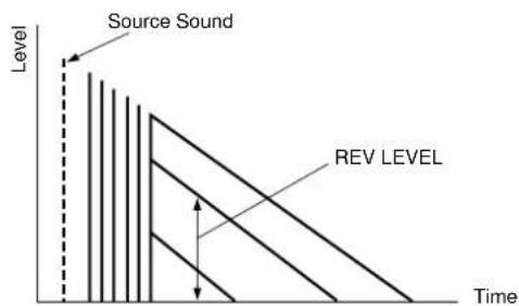
Appendix
Troubleshooting 79
Reference Chart for the INPUT and OUTPUT Jacks 82
CINEMA - EQ Frequency Characteristics 82
Specifications 83
Troubleshooting
Refer to the chart below when the DSP-AX1 does not function properly. If the problem you are experiencing is not listed below or if the instruction below does not help, turn the power off, disconnect the power cord, and contact your dealer or the nearest Yamaha Audio Products Service Department.
After this unit is exposed to strong external electric shock (such as lightning and large static electricity) or you mishandle the operation of this unit, it may not function properly. In these cases, turn the power off, unplug the power cord, plug it back in after 30 seconds, and start operating.
General
Problem Possible Cause What to Do
| The unit fails to turn on when STANDBY/ON is pressed, or returns to standby mode suddenly soon after the power is turned on. | The power cord is not plugged in or is not completely inserted. | Plug in the power cord securely (see page 24). |
| IMPEDANCE SELECTOR on the rear panel is not set correctly. | Set the switch completely to either position (depending on your speakers) while this unit is in standby mode (see page 22). |
| The protection circuitry has been activated. | Make sure all speaker wire connections on this unit and on all speakers are secure and that the wire for each connection does not touch anything other than its respective connection. |
| Hum | There is a faulty cable connection. | Connect the audio plugs securely. If the problem persists, the cords may be defective. |
| No connection from the turntable to the GND terminal. | Connect the grounding cord of your turntable to the GND terminal of this unit (see page 16). |
| No Sound or no picture | The volume is turned down. | Turn up the volume. |
| Faulty or incorrect input or output connection. | Connect the equipment correctly. If the problem persists, the cords may be defective. |
| Incorrect input source. | Select the appropriate input source with INPUT SELECTOR. |
| This unit is set to DTS input mode. | Press INPUT MODE to select another input mode |
| Digital signals other than PCM audio, Dolby Digital, or DTS encoded signals are input to this unit by playing a CD-ROM, etc. | Play a source whose signals this unit can reproduce. |
| No picture | The source equipment is connected to this unit using an S-video cable, but there is no S-video connection between this unit and your video monitor. | Connect this unit's S VIDEO MONITOR OUT terminal to the TV's S-video input terminal or disconnect the S-video cable from the source equipment. |
| No sound is coming from one side. | There is a faulty cable connection. | Connect all cables securely. If the problem persists, the cords may be defective. |
| BALANCE is turned all the way to one side. | Adjust BALANCE. |
| The volume level cannot be increased very much when adjusting VOLUME. | MUTE is on. | Turn VOLUME to minimum, press MUTE to restore audio, and adjust the volume again. |
| The equipment connected to the TAPE/ MD OUT jacks of this unit is turned off. | Turn on the power to the equipment. |
| The sound suddenly goes off. | The protection circuitry has been activated because of short circuit etc. | Reset the protection circuitry by turning the unit off and on. |
| The SLEEP timer came on. | Cancel the SLEEP timer function. |
Troubleshooting
| Problem | Possible Cause What to Do |
| No sound is coming from the Effect speakers. | The effect is off. | Press EFFECT to turn on the effect sound. |
| A Dolby Surround or DTS decoding sound field program is being used with material not encoded with Dolby Surround or DTS. | Select another sound field program. |
| No sound is coming from the Front Effect speakers. | PRO LOGIC/Normal, DOLBY DIGITAL/ Normal or DTS DIGITAL SUR./Normal of DSP program 12 is selected. | Select another sound field program. |
| The front level is turned to minimum. | Adjust the Front Effect speaker level (see page 63). |
| The 1F. FRNT EFCT item in the SET MENU is set to "NONE". | Select "YES" (see page 41). |
| No sound is coming from the Center speaker. | The 1A. CENTER SP item in the SET MENU is set to "NONE". | Select the appropriate mode for your Center speaker (see page 39). |
| One of the Hi-Fi DSP sound field programs (1 to 6) is selected. | Select another sound field program. |
| The input signals of a source encoded with Dolby Digital or DTS do not include center channel signals. | Refer to the instructions for the source currently playing. |
| No sound is coming from the Rear Effect speakers. | The right and left Rear speaker levels are set to minimum. | Increase the right and left Rear speaker levels (see page 63). |
| A monaural source is played with sound field program 12. | Select another sound field program. |
| No sound is coming from the Subwoofer. | The 1E. LFE/BASS OUT item in the SET MENU is set to "MAIN" when a Dolby Digital or DTS encoded software is played. | Select "SW" or "BOTH" (see page 40). |
| The 1E. LFE/BASS OUT item in the SET MENU is set to "SW" or "MAIN" when a 2-channel encoded software is played. | Select "BOTH" (see page 40). |
| Poor bass reproduction. | The 1E. LFE/BASS OUT item in the SET MENU is set to "SW" or "BOTH" and your system does not include a subwoofer. | Select "MAIN" (see page 40). |
| The output mode selection for each channel (MAIN, CENTER or REAR) in the SET MENU does not match your speaker configuration. | Select the appropriate output mode for each channel based on the size of the speakers in your configuration (see pages 37 through 41). |
| The volume level cannot be increased, or sound is distorted. | The power to the equipment connected to the REC OUT jacks of this unit is off. | Turn on the power to the equipment. |
| DSP parameters and some other settings on this unit cannot be changed. | The 13. MEMORY GUARD item in the SET MENU is set to "ON". | Select "OFF" (see page 48). |
| This unit does not operate properly. | The internal microcomputer has been frozen by an external electric shock (such as lightning or excessive static electricity) or by a power supply with low voltage. | Disconnect the AC power cord from the outlet, then plug it in again after about one minute. |
Troubleshooting
Problem
Possible Cause What to Do
| A source cannot be recorded by a tape deck or VCR connected to this unit. | The source unit is connected to this unit using digital jacks only. | Make additional connections to the analog jacks (see pages 16 through 19). |
| “CHECK SP WIRES!” appears on the display. | Speaker cables are short circuited. | Make sure all speaker cables are connected correctly. |
| There is noise from a nearby TV or tuner. | This unit is too close to the affected equipment. | Move this unit farther away from the affected equipment. |
| The sound is degraded when listening with the headphones connected to the CD player or cassette deck that are connected to this unit. | The power to this unit is off. | Turn on the power to this unit. |
| “INPUT DATA ERROR” appears on the display and no sound is heard. | A non-standard source is played back, or the equipment playing back the source is not operating correctly. | Check the source, or turn off the source equipment, then turn it on again. |
Remote Control
Problem
Possible Cause What to Do
| The remote control does not work. | The batteries are dead. | Replace the batteries with new ones and press RESET (see page 5). |
| The internal microcomputer has “frozen”. | Press RESET on the remote control (see page 5). |
| The remote control does not function properly. | Wrong distance or angle. | The remote control will function within a maximum range of 6 m (20 feet), no more than 30 degrees off-axis from the front panel (see page 5). |
| Direct sunlight or lighting (such as an inverter type of fluorescent lamp) is striking the remote control sensor of this unit. | Change the position of this unit. |
| The internal microcomputer has “frozen”. | Press RESET on the remote control (see page 5). |
| The remote control does not “learn” new functions. (The TRANSMIT indicator does not light up or flash.) | The batteries of this remote control and/or the other remote control are too weak. | Replace the batteries (and press RESET on the remote control) (see page 5). |
| The distance between the two remote controls is too far or near. | Place the remote controls at the proper distance (see page 58). |
| The signal coding or modulation of the other remote control is not compatible with this remote control. | Learning is not possible. |
| Memory capacity is full. | Further learning is not possible without deleting unnecessary new functions (see page 62). |
| The internal microcomputer has “frozen”. | Press RESET on the remote control (see page 5). |
| Continuous functions such as volume are learned, but operate only for a moment before stopping. | The learning process is incomplete. | Be sure to press and hold the function button on the other remote control until TRANSMIT begins flashing slowly. |
Reference Chart for the INPUT and OUTPUT Jacks
| SIGNAL | AUDIO | VIDEO |
| ANALOG | DIGITAL | COMPOSITE | S-VIDEO | COMPONENT |
| IN | OUT | COAXIAL | OPTICAL | IN OUT | IN OUT | IN OUT | | |
| IN OUT IN | | OUT |
| PHONO | O | | | | | | | | | | | |
| CD | O | | O | | O | | | | | | | |
| TUNER | O | | | | | | | | | | | |
| TAPE | O | O | | | | | | | | | | |
| MD | O | O | | | O | O | | | | | | |
| DVD | O | | O | | O | | O | | O | | O · 1 | |
| LD | O | | RF | | O | | O | | O | | | |
| D-TV | O | | | | O | | O | | O | | O · 1 | |
| CBL/SAT | O | | O | | O | | O | | O | | O · 1 | |
| VCR 1, 2, 3 | O | O | | | O · 2 | | O | O | O | O | | |
| V-AUX | O | | | | | | O | | O | | | |
| 6 CH INPUT | O | | | | | | | | | | | |
| SUBWOOFER | | O · 3 | | | | | | | | | | |
| ZONE 2 OUT | | O | | | | | | O | | | | |
| MONITOR OUT | | | | | | | | O O | | O O | | O |
| SPEAKER OUT | | O · 4 | | | | | | | | | | |
| HEADPHONES | | O | | | | | | | | | | |
*1 This input can be changed to another video input by using the SET MENU. *2 Only for VCR 1
*3 SPLIT L,R, and MONO outputs *4 MAIN L,R, CENTER, FRONT L,R, REAR L,R, and REAR CENTER total 8 channels
CINEMA - EQ Frequency Characteristics
Cinema EQ is a digital equalizer that lets you independently adjust the sound quality of each speaker.
■HIGH (High Shelving Filter): Adjusts high frequency response smoothly. There are 16 responses affecting frequencies in the 1 to 12.7 kHz range, while gain is adjusted between +6 and -9 dB.
■PEQ (Parametric Equalizer): Allows smooth boost and cut at an arbitrary frequency range. The center frequency can be in the 1 to 12.7 kHz range, with gain between +6 and -9 dB.
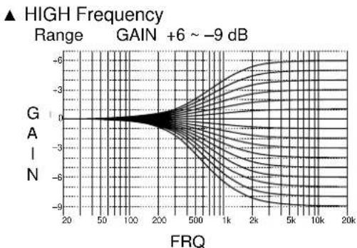
line
| FRQ | Gain |
|-------|------|
| 20 | 0 |
| 50 | 0 |
| 100 | 0 |
| 200 | 0 |
| 500 | -3 |
| 1k | -6 |
| 2k | -7 |
| 5k | -8 |
| 10k | -8.5 |
| 20k | -9 |
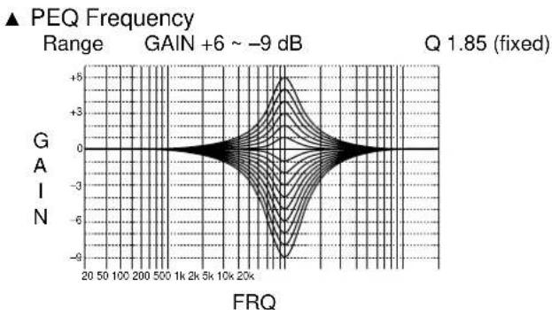
line
| FRQ Range | PEQ Frequency |
| --------- | ------------- |
| 20-50 | 0 |
| 50-100 | 0 |
| 100-200 | 0 |
| 200-500 | 0 |
| 500-1k | 0 |
| 1k-2k | 0 |
| 2k-5k | 0 |
| 5k-10k | 0 |
| 10k-20k | 0 |
| 20k-50k | 0 |
| 50k-100k | 0 |
| 100k-20k | 0 |
| 20k-50k | 0 |
| 50k-1k | 0 |
| 1k-2k | 0 |
| 2k-5k | 0 |
| 5k-10k | 0 |
| 10k-20k | 0 |
| 20k-50k | 0 |
| 50k-1k | 0 |
| 1k-2k | 0 |
| 2k-5k | 0 |
| 5k-10k | 0 |
| 10k-20k | 0 |
| 20k-50k }+5 |
| 50k-1k }+3 |
| 1k-2k }+1 |
| 2k-5k }+3 |
| 5k-10k }+5 |
| 10k-20k }+3 |
| 20k-50k }+1 |
| 50k-1k }+3 |
| 1k-2k }+5 |
| 2k-5k }+3 |
| 5k-10k }+1 |
| 10k-20k }+3 |
| 20k-50k }+5 |
| 50k-1k }+3 |
| 1k-2k }+1 |
| 2k-5k }+3 |
| 5k-10k }+5 |
| 10k-20k }+3 |
| 20k-50K }+1 |
| 50K-1k }+3 |
| 1K-2k }+5 |
| 2K-5k }+3 |
| 5K-10k }+1 |
| 1K-2K }+3 |
| 2K-5K }+5 |
| 5K-10K }+3 |
| 1K-2K }+1 |
| 2K-5K }+3 |
| 5K-10K }+5 |
| 1K-2K }+3 |
| 2K-5K }+1 |
| 5K-10K }+3 |
| 1K-2K }+5 |
| 2K-5K }+3 |
| 5K-10K }+1 |
| 1K-2K }+3 |
| 2K-5K }+5 |
| 5K-10K }+3 |
| 1K-2K }+1 |
| 2K-5K }+3 |
| 5K-10K }+5 |
| 1K-2 | +3 |
| 2K-5K }+1 |
| 5K-10K }+3 |
| 1K-2 | +5 |
| 2K-5K }+3 |
| 5K-10K }+1 |
| 1K-2 | +3 |
| 2K-5K }+1 |
| 5K-10K }+3 |
| 1K-2 | +5 |
| 2K-5K }+3 |
| 5K-10K }+1 |
| 1K-2 | +3 |
| 2C | +5 |
| C | +3 |
| D | +1 |
| E | +3 |
| F | +5 |
| G | +3 |
| H | +1 |
| I | +3 |
| J | +5 |
| K | +3 |
| L | +1 |
| M | +3 |
| N | +5 |
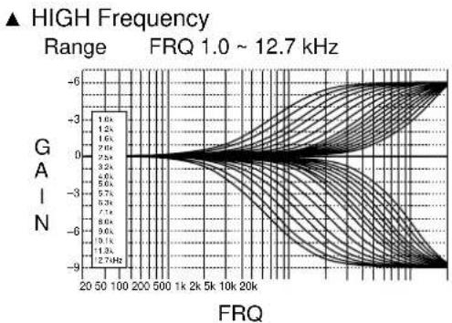
line
| FRQ | Gain |
| ------- | ---- |
| 20 | -6 |
| 50 | -3 |
| 100 | -1 |
| 200 | 0 |
| 500 | -3 |
| 1k | -6 |
| 2k | -3 |
| 5k | -1 |
| 10k | 0 |
| 20k | -3 |
| 500 | -6 |
| 1k | -9 |
| 2k | -6 |
| 5k | -3 |
| 10k | -1 |
| 2k | 0 |
| 5k | -3 |
| 10k | -6 |
| 2k | -9 |
| 500 | -6 |
| 1k | -3 |
| 2k | -1 |
| 5k | 0 |
| 10k | -3 |
| 2k | -6 |
| 500 | -9 |
| 1k | -6 |
| 2k | -3 |
| 5k | -1 |
| 10k | 0 |
| 2k | -3 |
| 500 | -6 |
| 1k | -9 |
| 2k | -6 |
| 5k | -3 |
| 10k | -1 |
| 2k | 0 |
| 500 | -3 |
| 1k | -6 |
| 2k | -9 |
| 500 | -6 |
| 1k | -3 |
| 2k | -1 |
| 500 | 0 |
| 1k | -3 |
| 2k | -6 |
| 500 | -9 |
| 1k | -6 |
| 2k | -3 |
| 500 | -1 |
| 1k | 0 |
| 2k | -3 |
| 500 | -6 |
| 1k | -9 |
| 2k | -6 |
| 500 | -3 |
| 1k | -1 |
| 2k | 0 |
| 500 | -3 |
| 1k | -6 |
| 2k | -9 |
| 500 | -6 |
| 1k | -3 |
| 2k | -1 |
| 500 | 0 |
| 1k | -3 |
|2.74Hz
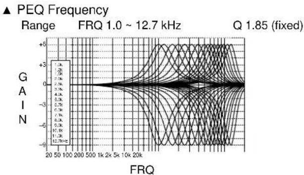
line
| FRQ Range | GAIN |
| --------- | ---- |
| 20-50 | +3 |
| 50-100 | 0 |
| 100-200 | -3 |
| 200-500 | -6 |
| 500-1k | -9 |
| 1k-2k | -6 |
| 2k-5k | -3 |
| 5k-10k | 0 |
| 10k-20k | +3 |
| 20k+ | 0 |
Audio Section
Minimum RMS Output Power per Channel
MAIN L/R, CENTER, REAR L/R/C
(20 Hz to 20 kHz, 0.015% THD, 8 ohms) ---- 110 W
FRONT L/R (1 kHz, 0.05% THD, 8 ohms) ---- 35 W
Maximum Power [for General and China models]
MAIN L/R, CENTER, REAR L/R/C
(1 kHz, 10% THD, 8 ohms) 150 W
FRONT L/R (1 kHz, 10 %THD, 8 ohms) ---- 45 W
Dynamic Power (IHF) [for General and China models]
MAIN L/R (8/6/4/2 ohms) 150/180/240/340 W
Dynamic Headroom [for General and China models]
MAIN L/R (8 ohms) 1.3 dB
DIN Standard Output Power per Channel
[for Europe and U.K. models]
MAIN L/R (1 kHz, 0.7% THD, 4 ohms) ---- 180 W
IEC Power [for Europe and U.K. models]
MAIN L/R (1 kHz, 0.015 % THD, 8 ohms)---- 120 W
Power Band Width
MAIN L/R (55 W, 0.04% THD, 8 ohms)
10 Hz to 50 kHz
Damping Factor
MAIN L/R (20 Hz to 20 kHz, 8 ohms) ---- 200 or more
Input Sensitivity/Impedance (110 W/8 ohms)
CD, etc. 150 mV/47 k-ohms
PHONO MM 2.5 mV/47 k-ohms
MAIN IN 1 V/47 k-ohms
Output Level/Impedance
REC OUT 150 mV/600 ohms
MAIN OUT 1 V/1.2 k-ohms
SUBWOOFER [SPLIT L/R] ---- 2 V/1.2 k-ohms
[MONO] ----4 V/1.2 k-ohms
PHONES Output 150 mV/100 ohms
Frequency Response (10 Hz to 100 kHz)
CD, etc. to MAIN L/R SP. OUT ---- -3 dB
Total Harmonic Distortion (20 Hz to 20 kHz)
CD, etc. to MAIN OUT (1 V) 0.005% or less
MAIN IN to SP OUT (55 W/8 ohms) ---- 0.005% or less
Signal to Noise Ratio (IHF-A network)
(Input shorted, EFFECT off) 96 dB or more
Residual Noise (IHF-A network)
MAIN L/R SP. OUT 150 ∝ V or less
Channel Separation (Vol -30 dB, 5.1 k-ohms terminated)
1 kHz/10 kHz 70 dB/60 dB or more
Tone Control (MAIN L/R)
Bass Boost/Cut ----±10 dB (50 Hz)
Treble Boost/Cut —— ±10 dB (20 kHz)
Bass Extension ---- +6 dB (60 Hz)
Video Section
Video Signal Type
[Europe and U.K. models] PAL
[General and China models] ---- NTSC/PAL
Composite Video Signal Level ---- 1 Vp-p/75 ohms
S-Video Signal Level
Y----1 Vp-p/75 ohms
C 0.286 Vp-p/75 ohms
Component Video Signal Level
Y---- 1 Vp-p/75 ohms
P_B / C_B Pr / Cr 0.7 Vp-p/75 ohms
Maximum Input Level 1.5 Vp-p
Signal to Noise Ratio 50 dB or more
Frequency Response
(MONITOR OUT) 5 Hz to 10 MHz, -3 dB
General
Power Supply
[Europe and U.K. models] ---- AC 230 V, 50 Hz
[Other models] ----AC 110/120/220/240 V, 50/60 Hz
Power Consumption---- 550 W
AC Outlets (Total 100 W maximum)
[U.K. model]---- 1 (Switched)
[Other models] 3 (Switched)
Dimensions (W x H x D) ----471 x 211 x 473 mm
(18-1/2" x 8-1/4" x 18-5/8")
Weight 28 kg (61 lbs 11oz)
Accessories ---- Remote control
Alkaline batteries
Quick reference guide
*Specifications are subject to change without notice.
ATTENTION: LISEZ CECI AVANT D'UTILISER L'APPAREIL.
natural_image
Technical line drawing of a mechanical assembly with no visible text or symbols
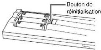
natural_image
Technical line drawing of a mechanical clamp or bracket assembly with a downward arrow indicating force or motion (no text or symbols present)
⑯BASS EXTENSION ON/OFF
⑰PROCESSOR DIRECT ON/OFF
⑧Prises DIGITAL OPTICAL/COAXIAL
⑪Prises REMOTE 1 IN/OUT/REMOTE 2 IN

natural_image
Diagram of a tool interacting with three cylindrical components (no text or symbols visible)
Fiche banane
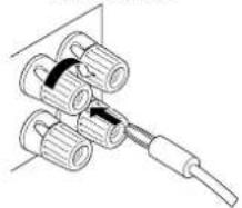
natural_image
Technical line drawing of a mechanical assembly with cylindrical components and a cable (no text or symbols)
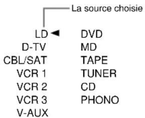
| 1 | 2 | Church | Jazz Club | Rock Concert | Entertainment |
| Europe Hall A | U.S.A. Hall D | Tokyo | Village Gate | Roxy Theatre | Disco |
| Europe Hall B | Europe Hall E | Freiburg | Village Vanguard | Warehouse Loft | Party |
| Europe Hall C | Live Concert | Royaumont | The Bottom Line | Arena | Game/Amusement |
Corrections CINEMA-DSP
| Concert Video 1 | Concert Video 2 | TV Theater | Movie Theater 1 | Movie Theater 2 | ☐☐/ DTS SURROUND |
| Pop/Rock DJ | Classical/Opera Pavilion | Mono Movie Variety/Sports | Spectacle Sci-Fi | Adventure General | Normal/Matrix 6.1/ES Enhanced/6.1/ES |
REC OUT/ZONE 2
SOURCE/REMOTE
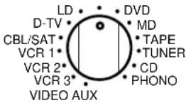
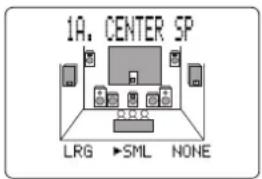
1A. CENTER SP
▶LRG SML NONE
■ 1B. MAIN SP (Enceintes principales)
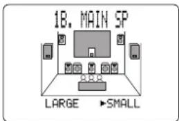
1B. MAIN SP
▶LARGE SMALL
Remarque:
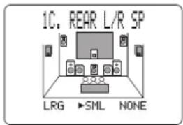
Pas d'enceinte
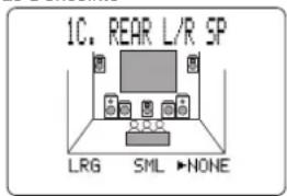
1C. REAR L/R SP
▶LRG SML NONE
Petite taille
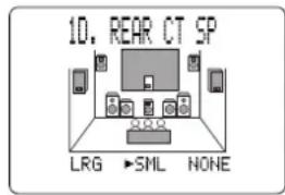
Pas d'enceinte
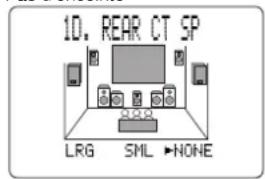

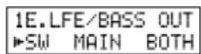
Remarque:
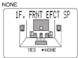
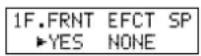
■ 1G. MAIN LEVEL

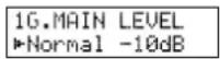
Remarque:
- LOW FREQ. TEST
FREQ. ……88Hz
Remarque:
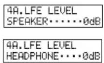
line
| Fréquence | Gain |
| --------- | ---- |
| Low | High |
| Medium | High |
| High | High |
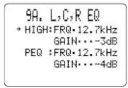
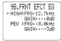
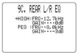
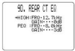
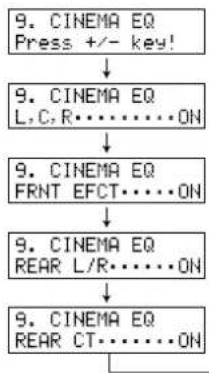
flowchart
graph TD
    A["9. CINEMA EQ Press +/- key!"] --> B["9. CINEMA EQ L,C,R......ON"]
    B --> C["9. CINEMA EQ FRNT EFCT......ON"]
    C --> D["9. CINEMA EQ REAR L/R......ON"]
    D --> E["9. CINEMA EQ REAR CT......ON"]
    E --> F["End"]
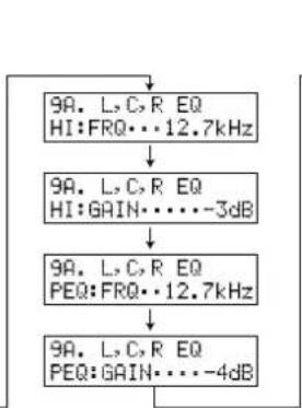
flowchart
graph TD
    A["9A. L, C, R EQ\nHI:FRQ...12.7kHz"] --> B["9A. L, C, R EQ\nHI:GAIN...3dB"]
    B --> C["9A. L, C, R EQ\nPEQ:FRQ...12.7kHz"]
    C --> D["9A. L, C, R EQ\nPEQ:GAIN...4dB"]
    D --> A
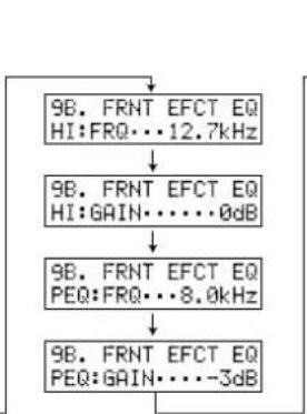
flowchart
graph TD
    A["9B. FRNT EFCT EQ\nHI:FRQ...12.7kHz"] --> B["9B. FRNT EFCT EQ\nHI:GAIN...0dB"]
    B --> C["9B. FRNT EFCT EQ\nPEQ:FRQ...8.0kHz"]
    C --> D["9B. FRNT EFCT EQ\nPEQ:GAIN...-3dB"]
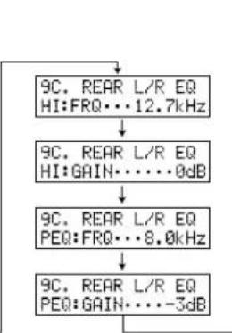
flowchart
graph TD
    A["9C. REAR L/R EQ HI:FRQ...12.7kHz"] --> B["9C. REAR L/R EQ HI:GAIN...0dB"]
    B --> C["9C. REAR L/R EQ PEQ:FRQ...8.0kHz"]
    C --> D["9C. REAR L/R EQ PEQ:GAIN...-3dB"]
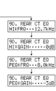
flowchart
graph TD
    A["90. REAR CT EQ HI:FRQ...12.7kHz"] --> B["90. REAR CT EQ HI:GAIN...0dB"]
    B --> C["90. REAR CT EQ PEQ:FRQ...8.0kHz"]
    C --> D["90. REAR CT EQ PEQ:GAIN...-3dB"]
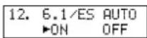
13. MEMORY GUARD (Protection de la mémoire)
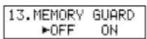
Remarques:
natural_image
Interior view of a modern auditorium with tiered seating and central stage (no visible text or symbols)
Anomalies Causes possibles Actions correctives
Anomalies
Causes possibles Actions correctives
Anomalies
Causes possibles Actions correctives
MAIN L/R, CENTER, REAR L/R/C
MAIN L/R, CENTER, REAR L/R/C
(1 kHz, DHT 10%, 8 Ohms) 150 W
FRONT L/R (1 kHz, DHT 10%, 8 Ohms)---- 45 W
MAIN L/R (8/6/4/2 Ohms) 150/180/240/340 W
MAIN IN 1 V/47 kOhms
REC OUT 150 mV/600 Ohms
MAIN OUT 1 V/1,2 kOhms
SUBWOOFER [SPLIT L/R] ---- 2 V/1,2 kOhms
[MONO] 4 V/1,2 kOhms
Sortie PHONES---- 150 mV/100 Ohms
natural_image
Technical line drawing of a mechanical clamp or bracket assembly (no text or symbols)
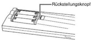
natural_image
Technical line drawing of a mechanical clamp or bracket assembly with no visible text or symbols
Fernbedienung
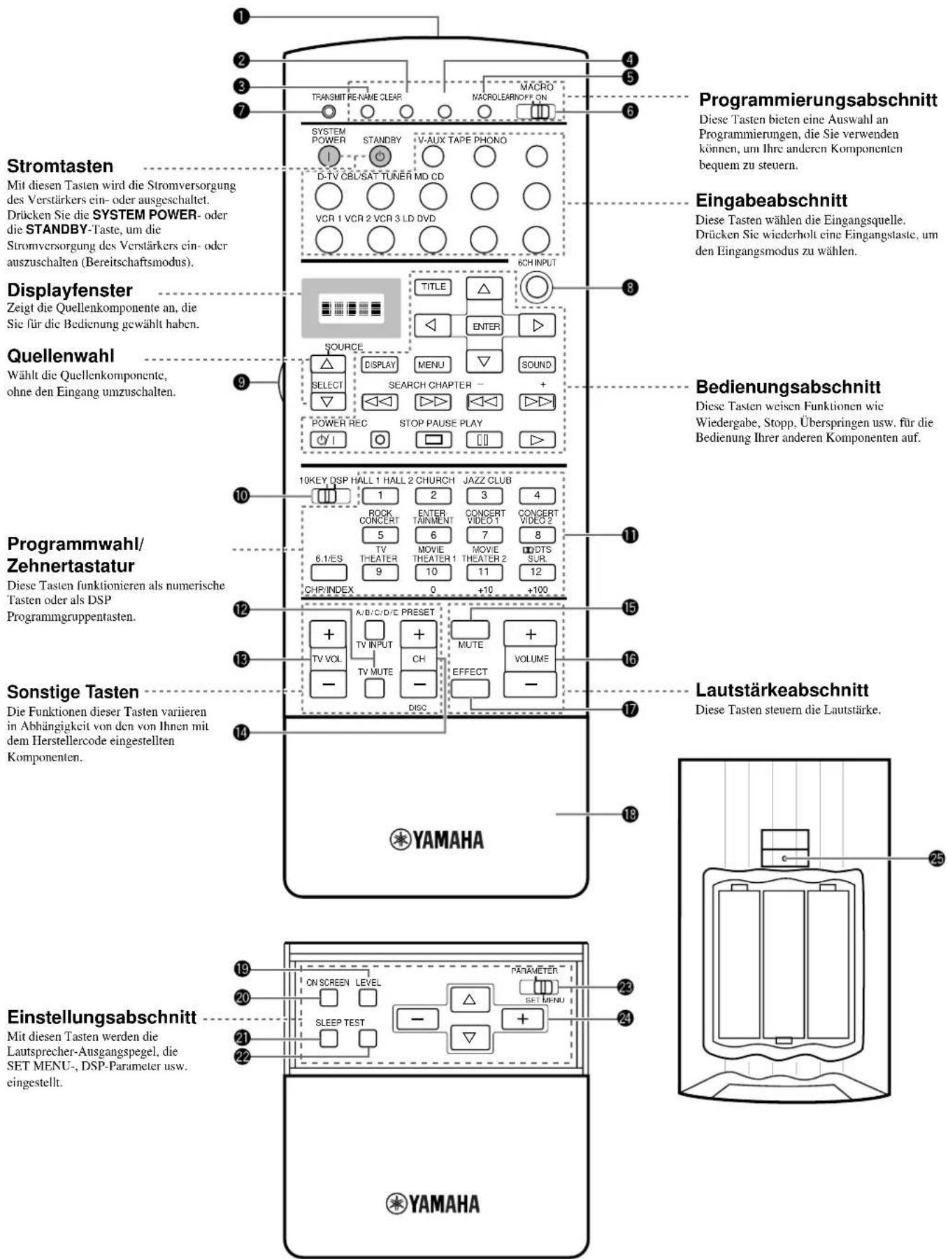
natural_image
Diagram of a tool interacting with three cylindrical objects (no text or symbols visible)
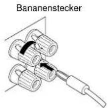
On-Screen-Display (OSD)
flowchart
graph TD
    L[" L "] --> R[" R "]
    C[" C "] --> R[" R "]
    FR[" FR "] --> R[" R "]
    RL[" RL "] --> RC[" RC "]
    RC --> RL[" RL "]
    RL --> RL[" RL "]
    style RL fill:#99ccff,stroke:#333
    style RC fill:#cccccc,stroke:#333
    style FL fill:#ffffff,stroke:#333
    style C fill:#ffffff,stroke:#333
    style R fill:#ffffff,stroke:#333
    style RR fill:#ffffff,stroke:#333
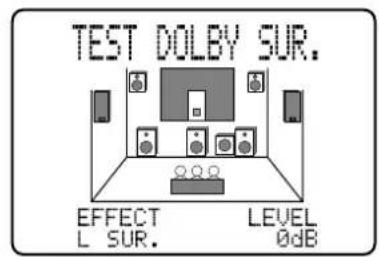
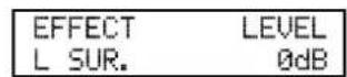
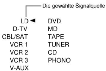
| 1 | 2 | Church | Jazz Club | Rock Concert | Entertainment |
| Europe Hall A | U.S.A. Hall D | Tokyo | Village Gate | Roxy Theatre | Disco |
| Europe Hall B | Europe Hall E | Freiburg | Village Vanguard | Warehouse Loft | Party |
| Europe Hall C | Live Concert | Royaumont | The Bottom Line | Arena | Game/Amusement |
CINEMA-DSP-Programme
| Concert Video 1 | Concert Video 2 | TV Theater | Movie Theater 1 | Movie Theater 2 | ☐☐/ DTS SURROUND |
| Pop/Rock DJ | Classical/Opera Pavilion | Mono Movie Variety/Sports | Spectacle Sci-Fi | Adventure General | Normal/Matrix 6.1/ES Enhanced/6.1/ES |
KeinKlein
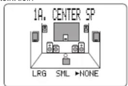
1A. CENTER SP
▶LRG SML NONE
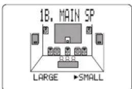
1B. MAIN SP
▶LARGE SMALL
Hinweis:
KeinKlein
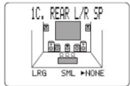
1C. REAR L/R SP
▶LRG SML NONE
NONE
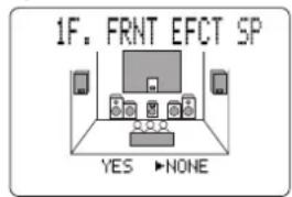
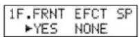
■ 1G. MAIN LEVEL (Hauptpegel)
-10dB
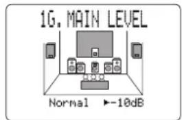
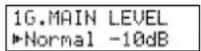
Hinweis:
Hinweis:
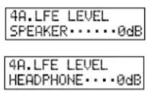
line
| Frequency | Value |
| --------- | ----- |
| PsQ | High |
| + PsQ | Low |
▲ Vorderer (FRONT) und hinterer (REAR) Einstellwert
HIGH : FRQ 12.7 kHz GAIN 0dB
PEQ : FRQ 8.0 kHz GAIN -3dB
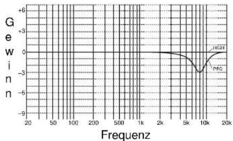
line
| Freqenz | Gewinn |
| ------- | ------ |
| 20 | +6 |
| 50 | +6 |
| 100 | +6 |
| 200 | +6 |
| 500 | +6 |
| 1k | +6 |
| 2k | +6 |
| 5k | +6 |
| 10k | -3 |
| 20k | +6 |
9A. L, C, R EQ
HI: FRQ···12.7kHz
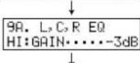
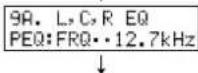
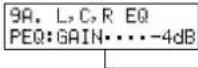
- FRNT EFCT EQ HI:FRQ···12.7kHz
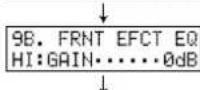
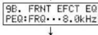
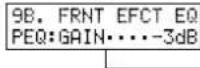
9C. REAR L/R EQ HI:FRQ···12.7kHz
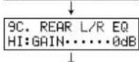
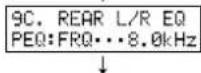
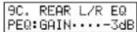
9D. REAR CT EQ
HI:FRQ···12.7kHz
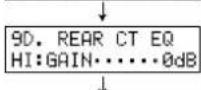
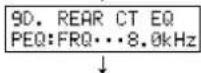
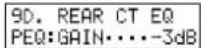

RC. ROOM SIZE (Rear Center Room Size = Hintere Center- 76
Raumgröße) 76
RC. LIVENESS (Rear Center Liveness = Hintere Center-Lebendigkeit) ..... 76
REV. TIME (Reverberation Time = Widerhallzeit) 77
natural_image
Interior view of a modern auditorium with tiered seating and central stage (no visible text or symbols)
■ Verschiedenes/Sport (Variety/Sports)
RC. LIVENESS (Rear Center Liveness = Hintere Center-Lebendigkeit)
line
| Freqenz | Gewinn |
| ------- | ------ |
| 20 | 0.0 |
| 50 | 0.0 |
| 100 | 0.0 |
| 200 | 0.0 |
| 500 | 0.0 |
| 1k | 0.0 |
| 2k | 0.0 |
| 5k | 0.0 |
| 10k | 0.0 |
| 20k | 0.0 |
Audioteil
MAIN L/R, CENTER, REAR L/R/C
MAIN L/R, CENTER, REAR L/R/C
(1 kHz, 10% Klirr, 8 Ohm) 150 W
FRONT L/R (1 kHz, 10% Klirr, 8 Ohm) ---- 45 W
MAIN L/R (8/6/4/2 Ohm) 150/180/240/340 W
Quick Reference Card
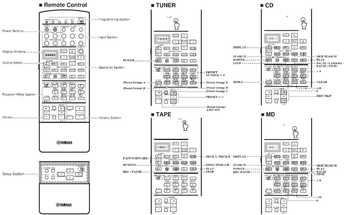
Quick Reference Card
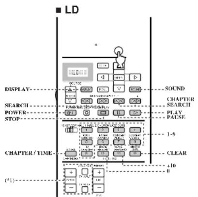
flowchart
graph TD
    A["LD"] --> B["DISPLAY"]
    B --> C["SEARCH"]
    C --> D["POWER STOP"]
    D --> E["CHAPTER/TIME"]
    E --> F["+10"]
    F --> G["<< Duration Control >"]
    G --> H["<< Duration Control >"]
    H --> I["<< Duration Control >"]
    I --> J["<< Duration Control >"]
    J --> K["<< Duration Control >"]
    K --> L["<< Duration Control >"]
    L --> M["<< Duration Control >"]
    M --> N["<< Duration Control >"]
    N --> O["<< Duration Control >"]
    O --> P["<< Duration Control >"]
    P --> Q["<< Duration Control >"]
    Q --> R["<< Duration Control >"]
    R --> S["<< Duration Control >"]
    S --> T["<< Duration Control >"]
    T --> U["<< Duration Control >"]
    U --> V["<< Duration Control >"]
    V --> W["<< Duration Control >"]
    W --> X["<< Duration Control >"]
    X --> Y["<< Duration Control >"]
    Y --> Z["<< Duration Control >"]
    Z --> AA["<< Duration Control >"]
    AA --> AB["<< Duration Control >"]
    AB --> AC["<< Duration Control >"]
    AC --> AD["<< Duration Control >"]
    AD --> AE["<< Duration Control >"]
    AE --> AF["<< Duration Control >"]
    AF --> AG["<< Duration Control >"]
    AG --> AH["<< Duration Control >"]
    AH --> AI["<< Duration Control >"]
    AI --> AJ["<< Duration Control >"]
    AJ --> AK["<< Duration Control >"]
    AK --> AL["<< Duration Control >"]
    AL --> AM["<< Duration Control >"]
    AM --> AN["<< Duration Control >"]
    AN --> AO["<< Duration Control >"]
    AO --> AP["<< Duration Control >"]
    AP --> AQ["<< Duration Control >"]
    AQ --> AR["<< Duration Control >"]
    AR --> AS["<< Duration Control >"]
    AS --> AT["<< Duration Control >"]
    AT --> AU["<< Duration Control >"]
    AU --> AV["<< Duration Control >"]
    AV --> AW["<< Duration Control >"]
    AW --> AX["<< Duration Control >"]
    AX --> AY["<< Duration Control >"]
    AY --> AZ["<< Duration Control >"]
    AZ --> BA["<< Duration Control >"]
    BA --> BB["<< Duration Control >"]
    BB --> BC["<< Duration Control >"]
    BC --> BD["<< Duration Control >"]
    BD --> BE["<< Duration Control >"]
    BE --> BF["<< Duration Control >"]
    BF --> BG["<< Duration Control >"]
    BG --> BH["<< Duration Control >"]
    BH --> BI["<< Duration Control >"]
    BI --> BJ["<< Duration Control >"]
    BJ --> BK["<< Duration Control >"]
    BK --> BL["<< Duration Control >"]
    BL --> BM["<< Duration Control >"]
    BM --> BN["<< Duration Control >"]
    BN --> BO["<< Duration Control >"]
    BO --> BP["<< Duration Control >"]
    BP --> BQ["<< Duration Control >"]
    BQ --> BR["<< Duration Control >"]
    BR --> BS["<< Duration Control >"]
    BS --> BT["<< Duration Control >"]
    BT --> BU["<< Duration Control >"]
    BU --> BV["<< Duration Control >"]
    BV --> BW["<< Duration Control >"]
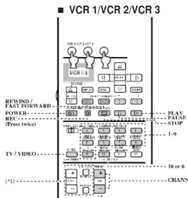
flowchart
graph TD
    A["VCR 1/VCR 2/VCR 3"] --> B["POWER"]
    B --> C["RFWIND / FAST FORWARD"]
    B --> D["REC (Press twice)"]
    B --> E["TV / VIDEO"]
    B --> F["CHANNEL"]
    style A fill:#f9f,stroke:#333
    style B fill:#ccf,stroke:#333
    style C fill:#cfc,stroke:#333
    style D fill:#fcc,stroke:#333
    style E fill:#cff,stroke:#333
    style F fill:#ffc,stroke:#333
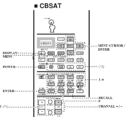
flowchart
graph TD
    A[" CBSAT "] --> B[" Display - MENU"]
    B --> C[" POWER - INPUT"]
    C --> D[" ENTER - OUTPUT"]
    D --> E[" RECALL 0"]
    E --> F[" CHANNEL +/-"]
    style A fill:#f9f,stroke:#333
    style B fill:#ccf,stroke:#333
    style C fill:#cfc,stroke:#333
    style D fill:#fcc,stroke:#333
    style E fill:#cff,stroke:#333
    style F fill:#ffc,stroke:#333
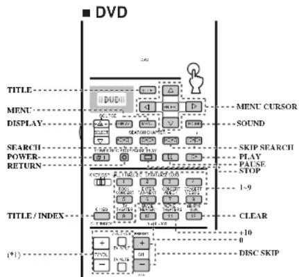
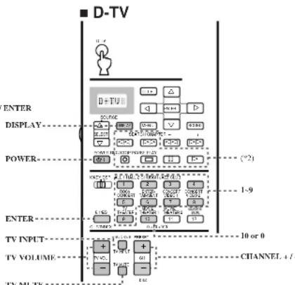
(*1) TV VOL, TV INPUT, TV MUTE function if you have setup the manufacturer code for the D-TV Area.
(°2) You can control your VCR if you have setup the code for VCR 1.