PROMIX66N - Mixer HQ Power - Free user manual and instructions
Find the device manual for free PROMIX66N HQ Power in PDF.
User questions about PROMIX66N HQ Power
0 question about this device. Answer the ones you know or ask your own.
Ask a new question about this device
Download the instructions for your Mixer in PDF format for free! Find your manual PROMIX66N - HQ Power and take your electronic device back in hand. On this page are published all the documents necessary for the use of your device. PROMIX66N by HQ Power.
USER MANUAL PROMIX66N HQ Power
PROFESSIONELLES 6-KANAL- / 8-KANAL-MISCHPULT
PROFESJONALNY MIKSER 6-CIO/8-MIO KANAŁOWY
USERMANUAL 2
GEBRUIKERSHANDLEIDING 8
MODE D'EMPLOI 14
MANUAL DEL USUARIO 19
To all residents of the European Union
Important environmental information about this product

This symbol on the device or the package indicates that disposal of the device after its lifecycle could harm the environment. Do not dispose of the unit (or batteries) as unsorted municipal waste; it should be taken to a specialized company for recycling. This device should be returned to your distributor or to a local recycling service. Respect the local environmental rules.

If in doubt, contact your local waste disposal authorities.
Thank you for choosing HQPower™! Please read the manual thoroughly before bringing this device into service. If the device was damaged in transit, don't install or use it and contact your dealer.
2. Safety Instructions
| Be very careful during the installation: touching live wires can cause life-threatening electroshocks. | |
| Indcor use only. Keep this device away from rain, moisture, splashing and dripping liquids. Never put objects filled with liquids on top of or close to the device. | |
| Alwa ys disconnect mains power when device not in use or when servicing or maintenance activities are performed. Handle the power cord by the plug only. |
Refer to the Velleman® Service and Quality Warranty on the last pages of this manual.
- Damage caused by disregard of certain guidelines in this in anual is not covered by the warranty and the dealer will not accept responsibility for any ensuing defects or problems.
- A qualified technician should install and service this device.
- Do not switch the device on immediately after it has been exposed to changes in temperature. Protect the device against damage by leaving it switched off until it has reached room temperature.
- Do not expose the device to liquids and make sure not to place any object containing liquid on top of the device.
Note that damage caused by user modifications to the device is not covered by the warranty. - Keep the device away from children and unauthorised users.
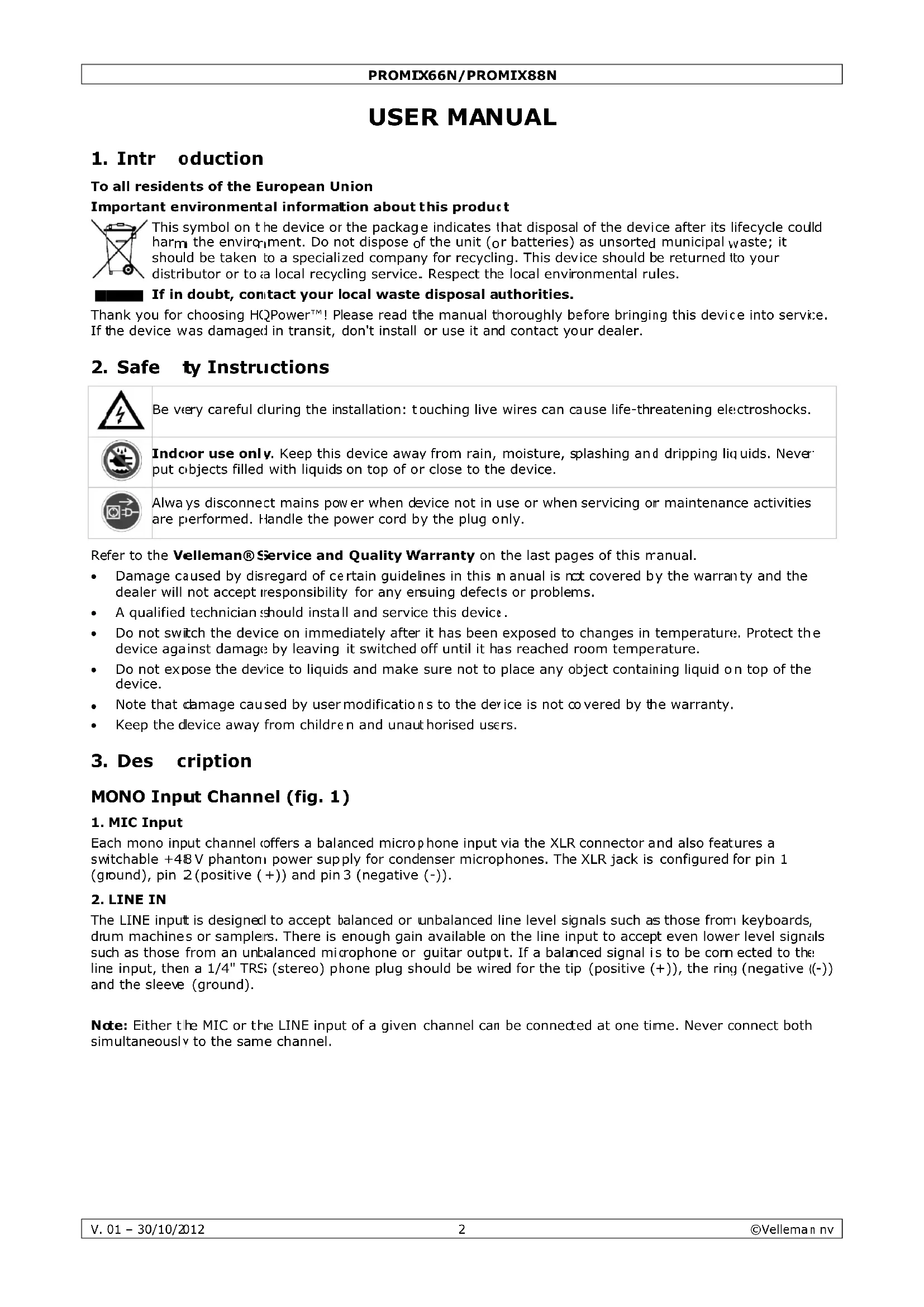
3. Des cription
MONO Input Channel (fig. 1)
1. MIC Input
Each mono input channel offers a balanced microphone input via the XLR connector and also features a switchable +48V phantom power supply for condenser microphones. The XLR jack is configured for pin 1 (ground), pin 2 (positive (+)) and pin 3 (negative (-)).
2. LINE IN
The LINE input is designed to accept balanced or unbalanced line level signals such as those from keyboards, drum machines or samplers. There is enough gain available on the line input to accept even lower level signals such as those from an unbalanced microphone or guitar output. If a balanced signal is to be connected to the line input, then a 1/4" TRS (stereo) phone plug should be wired for the tip (positive (+)), the ring (negative (-)) and the sleeve (ground).
Note: Either the MIC or the LINE input of a given channel can be connected at one time. Never connect both simultaneously to the same channel.
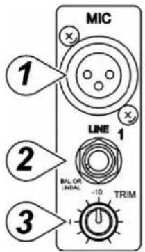
3. TRIM Control
The TRIM control adjusts the input sensitivity (channel gain) of the MIC and LINE inputs on the mono input channels. This control can be adjusted to accommodate input signals from a wide variety of sources, from the high outputs from keyboards or drum machines to the small signal outputs of microphones. This wide range eliminates the need for MIC / LINE switching. The best S/N balance and dynamic range will be achieved if you adjust the TRIM control on each channel separately so that the PEAK LED (7) for that channel lights occasionally.
Note: This control should always be turned fully anticlockwise whenever you connect or disconnect a signal source to one of the inputs.
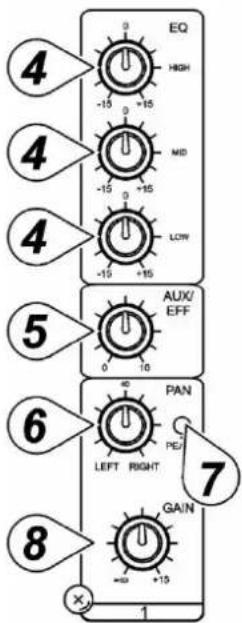
4. EQUALIZER Controls
All mono input channels are fitted with three-band EQ. The upper (HIGH) and lower (LOW) shelving controls have their frequencies fixed at 12kHz and 80Hz respectively. The midrange control has a peaking response, with Q fixed at 2 octaves and the frequency at 2.5kHz . All three bands have up to 15 dB of cut and boost with a centre detent for "off".
5. AUX / EFF SEND Control
The AUX / EFF controls are mono and post-EQ and post-fader. The signal level sent to the AUX / EFF bus will be affected by the channel fader setting. The AUX configuration is ideal for almost all monitoring purpose e.g. for a separate stage monitor mix in live performances or a studio room monitor in recording applications, such as for a headphone cue system. The EFF controls the adjustment of level sent by each channel to the internal DSP (Digital Sound Processor).
6. PAN Control
The channel PAN positions the output of the channel in the stereo field of the Master Mix. Its constant-power design ensures there are no level discrepancies whether a signal is hard-panned, centre-stage or somewhere in-between.
7. PEAK Indicator
The PEAK LED illuminates when a channel is going into overload. It detects the peak level after the EQ and will light at 3 dB before clipping to warn that the signal is approaching overload. You do not want the PEAK LED to light except very intermittently during a take or a mix. If it does light persistently, reduce input gain with the TRIM control (3).
8. CHANNEL GAIN Control
The channel GAIN controls determine the output signal level to the master mix bus. There is no PFL function on the mixer. In order to audition any single channel for proper gain, you can turn off the gain control of all the other channels (fully anticlockwise) and set both the auditioned channel and MASTER MIX control (29) to unity gain (0 dB). The LED OUTPUT meter (21) should read around 0 dB.
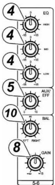
STEREO Input Channel (fig. 2)
4. EQUALIZER Controls
The stereo channel EQs operate in the same manner as those in the mono channels. The left and right signals will be affected equally. A stereo equalizer is generally preferable to using two mono equalizers when equalizing a stereo signal as it avoids possible discrepancies between the left and right settings.
5.AUX/EFFSENDControl
These are the same as for the mono channels. Note that a mono sum is taken from the stereo input.
8. CHANNEL GAIN CONTROL
The channel GAIN controls determine the output signal level to the MASTER MIX bus. There is no PFL function on the mixer. In order to audition any single channel for proper gain you can turn off the gain control of all the other channels (fully anticlockwise) and set both the auditioned channel and MASTER MIX control (29) to unity gain (0 dB). The LED OUTPUT meter (21) should read around 0 dB.
9. LINE IN
Each stereo channel has two balanced line level inputs on 1/4 TRS jacks for left and right channels (tip = positive (+), ring = negative (-), sleeve = ground). If only the connector marked "L" (left) is used, the channel operates in mono. The stereo channels are designed to handle typical line level signals. The input signals to these jacks can be either balanced or unbalanced.
10. BAL Control
For a mono input to the L (MONO) input the function of the control is the same as the PAN controls (6) of the mono channels. However, when a channel is run in stereo, this control functions as a BALANCE control, determining the relative balance of the left and right channel signals being sent to the left and right MASTER MIX buses. For example, with the BALANCE control turned fully clockwise, only the right portion of the channel's stereo signal will be routed to the MASTER MIX.
MASTER Section (fig. 3 & 4)
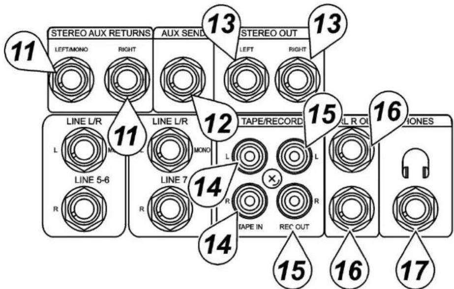
11. STEREO AUX RETURNS (LEFT / MONO, RIGHT)
The AUX RETURN jacks are the mono or stereo returns for AUX SEND. If you connect a signal to the LEFT / MONO RETURN jack only, the AUX RETURN will operate in mono and the signal will be routed to the AUX RETURN control (19) and then mixed into the left and right MASTER MIX stereo outputs (13). The separate left and right return jacks are provided for use with stereo signals such as those from the output of a stereo effects processor. The left and right return signals will be routed to the AUX RETURN level control (19) and mixed into the left and right STEREO OUT (13) while maintaining stereo separation.
12.AUXSEND
The AUX SEND is the output for the signal sent from the channel AUX / EFF controls (5) and by the AUX SEND controls (18) control. They are 1/4 unbalanced phone jacks (tip = positive (+), sleeve = ground). AUX SEND is a post-fader. These signals can be sent to the input of an effects processor, multi-track recorder, or used for any other line-level auxiliary purpose.
13. STEREO Outputs
Use these jacks to connect to an external power amplifier if extra output power for a larger PA system is required. The stereo outputs are left (L) and right (R) unbalanced 1/4'' phone jacks, wired as tip = positive (+), sleeve = ground.
14. TAPE Inputs
These jacks will accept the signal from an external device with a stereo output such as a cassette recorder.
15. REC Outputs
The REC outputs also provide an output of the MASTER MIX. These outputs are RCA jacks and designed primarily for inputs to tape recorders etc.
16. L-R Control Room Outputs
The L-R control room outputs can be connected to an amp to power stereo control room (or other) monitor speakers and are 1/4" unbalanced phone jacks, wired as tip = positive (+), sleeve = ground.
17. PHONES Output
The PHONES output will feed headphones and is a 1/4" TRS jack, wired as tip = left signal, ring = right signal, sleeve = ground.
18. AUX SEND
This is a master control that adjusts the output signal level at the AUX SEND (12) jack.
19. AUX RETURN Control
The left and right return signals will be routed to the AUX RETURN level control and mixed into the left and right stereo OUT (13) while maintaining stereo separation.
20. PHONES/CONTROL ROOM CONTROL
The mixer allows you to monitor the MASTER MIX. The signal level is adjusted with the PHONES / CONTROL ROOM control and routed to both the CONTROL ROOM (16) and HEADPHONES (17) outputs.
When using condenser microphones, +48 VDC can be switched globally on or off to the XLR MIC inputs for all mono channels. When this switch is in the "ON" position, the PHANTOM POWER ON LED (25) will light and +48 VDC will be provided between pins 2 and 3 on all the mono MIC input XLR connectors. If you do not need phantom power, be sure to turn this switch to the "OFF" position.
Note: It is safe to connect balanced dynamic microphones or line-level devices even if this switch is on, but connecting unbalanced devices or devices whose transformers are centre-grounded will cause hum or malfunctions. Shorting the +48 VDC can also damage your mixer. Also, mute the monitor or PA speakers first when turning the phantom power on or off.
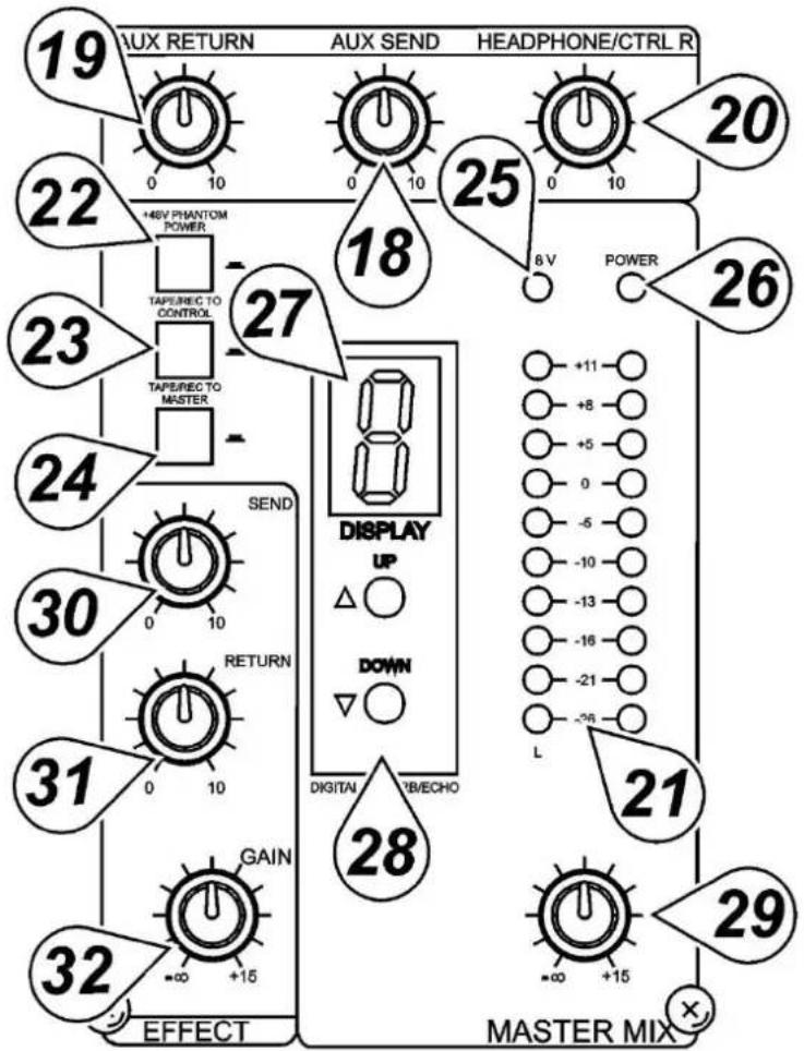
23. TAPE / REC TO CONTROL ROOM Switch
Use the TAPE / REC TO CONTOL ROOM switch to route signals from the TAPE input (14) to the PHONES / CONTROL ROOM control (20).
24 TAPE / REC TO MASTER Switch
Use the TAPE / ECHO TO MASTER switch to route signals from the TAPE input (14) to the MASTER MIX GAIN control (29).
25. PHANTOM POWER LED
The red +48V LED lights up when the phantom power is turned on.
26. POWER ON LED
The red LED indicates that the console is powered on.
DIGITAL EFFECTS Section
27. EFFECTS Display
Press either ECHO effect buttons to scroll in either direction through the 16 presets. The numeric effects display will indicate which of the 16 effect presets has been selected.
28. ECHO EFFECT SELECT Buttons
The built-in DSP (Digital Sound Processor) offers 16 different preset level and echo intervals selectable by the echo effect UP / DOWN buttons. The DSP processes the signal on the EFFECTS bus, which is the sum of the mono and stereo channel inputs controlled by the EFF control (5).
29. MASTER MIX GAIN Control
The output level routed to the stereo outputs and REC outputs is determined ultimately by the setting of the MASTER MIX GAIN control.
30.EFFECTSEND
The EFFECT SEND control adjusts the level of the signal on the EFFECTS bus fed to the DSP.
31. EFFECT (ECHO) RETURN
The EFFECT (ECHO) RETURN control adjusts the number of repeats of the echo effect selected with the UP / DOWN buttons (28).
32.EFFECT GAIN
The EFFECTS GAIN fader controls the signal level sent to the MASTER MIX buses.
Rear Panel (fig. 5)
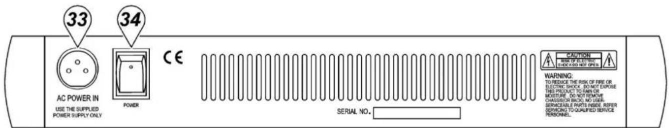
33. AC POWER IN Socket
Connect the enclosed power supply to the 3-pin mains connector on the rear of the console. Use the included adapter to connect the console to the mains.
34. MAIN POWER Switch
This switches the mixer ON or OFF.
Note: Be sure to switch on the power to your mixer before switching on the amplification system.
4. Connections
Unbalanced equipment may be connected to balanced inputs/outputs. Either use mono 1/4" jacks or connect the ring and sleeve of TRS jacks. Never use unbalanced XLR connectors on the MIC input connectors when using the phantom power supply.
Microphone input Group & mix outputs
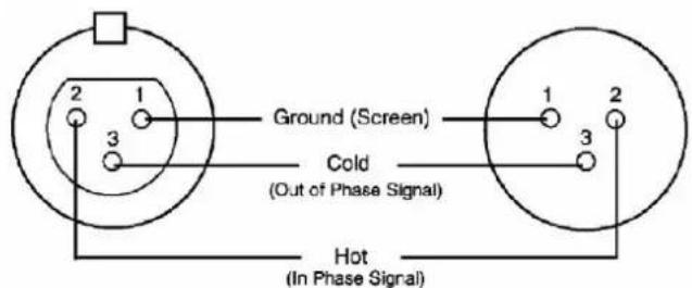
Socket (female) Plug (male)
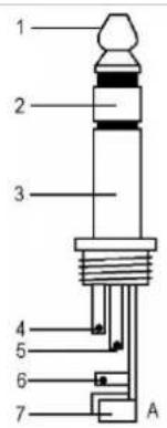
Headphones
- Tip = left signal
- Ring = right signal
- Sleeve = ground
- Tip
- Ring
- Sleeve
- Strain relief clamp
| 1 2 3 4 5 B | Unbalanced use of mono 1/4" plugs 1. Tip = signal 2. Sleeve = ground 3. Tip 4. Sleeve 5. Strain relief clamp |
| 1 2 3 4 5 6 7 | Balanced use of stereo 1/4" plugs 1. Tip = hot (+) 2. Ring = cold (-) 3. Sleeve = ground 4. Tip 5. Ring 6. Sleeve 7. Strain relief clamp |
5. Technical Specifications
Input
| Input Connector | Input Impedance | Nominal Level | Max. Level | |
| MONO CH MIC XLR | >1.3 kohm +2 dBm | +14 dBm | ||
| MONO CH LINE 1/4" | TRS >10 kohm +4 dBm | +22 dBm | ||
| STEREO CH LINE 1/4" | TRS >10 kohm +4 dBm | +22 dBm | ||
| TAPE IN | RCA PIN JACKS | >10 kohm | +2 dBm | +22 dBm |
| AUX RETURNS | 1/4" TRS >10 kohm +4 dBm +22 dBm | |||
Output
| Output | Connector | Input Impedance | Nominal Level | Max. Level |
| STEREO OUT L/R | 1/4" TRS | 120 ohm | +4 ~ 6 dBm | +22 dBm |
| AUX SEND | 1/4" TRS | 120 ohm | +4 ~ 6 dBm | +20 dBm |
| CTRL R OUT | 1/4" TRS | 120 ohm | +4 ~ 6 dBm | +22 dBm |
| REC OUT | RCA PIN JACKS | 1 kohm | +4 ~ 6 dBm | +22 dBm |
| PHONES | 1/4" TRS | 100 ohm | - | 40 mW * 2 |
| Frequency Response | 20 Hz to 20 kHz | |
| THD | 0.02 %, 20 Hz ~ 20 kHz @ 1 kHz, 0 dBm | |
| Input Channel Equalization | ||
| High | 12 kHz, +/- 15 dB, Q fixed at 2 octaves | |
| Mid | 2.5 kHz, +/- 15 dB, Q fixed at 1 octave | |
| Low | 80 Hz, +/- 15 dB, Q fixed at 2 octaves | |
| Gain Control Range | ||
| Input Channel Trim Control | stop to stop, MIC +10 dB ~ +60 dB; LINE +10 dB ~ +40 dB | |
| Channel/Master/Effect Faders | -∞ to +15 dB | |
| Aux Send/Aux Master Send | OFF to +15 dB | |
| Aux Return | OFF to +20 dB | |
| Channel and Master Effects Send | OFF to +15 dB | |
PROMIX66N/PROMIX88N
| Crosstalk @ 1 kHz | -78 dB ~ -68 dB | |
| Hum and Noise | 20 Hz - 20 kHz, Rs = 150 ohm, input TRIM @ 0 dB, sensitivity at -60 dB | |
| Equivalent Input Noise | -129 dBm | |
| Residual Output Noise | < 90 dBm | |
| VU Meters | 10-segment LED x 2 | |
| Phantom Power | +48 VDC | |
| Power Supply | 120 VAC / 60 Hz or 230 VAC / 50 Hz selectable | |
| Consumption | 25 W | |
| Dimensions | ||
| PROMIX66N | 253 x 236 x 55 mm | |
| PROMIX88N | 253 x 290 x 55 mm | |
| Weight | ||
| PROMIX66N | 1.72 kg | |
| PROMIX88N | 2 kg | |
Use this device with original accessories only. Velleman nv cannot be held responsible in the event of damage or injury resulting from (incorrect) use of this device.
For more info concerning this product and the latest version of this manual, please visit our website www.hqpower.eu.
The information in this manual is subject to change without prior notice.
© COPYRIGHT NOTICE
The copyright to this manual is owned by Velleman nv. All worldwide rights reserved.
No part of this manual may be copied, reproduced, translated or reduced to any electronic medium or otherwise without the prior written consent of the copyright holder.
GEBRUIKERSHANDLEIDING
1. Inlei ding
Section EFFETS NUMÉRIQUES
DIGITAL EFFECTS Section
Velleman® Service and Quality Warranty
Since its foundation in 1972, Velleman® acquired extensive experience in the electronics world and currently distributes its products in over 85 countries.
All our products fulfil strict quality requirements and legal stipulations in the EU. In order to ensure the quality, our products regularly go through an extra quality check, both by an internal quality department and by specialized external organisations. If, all precautionary measures notwithstanding, problems should occur, please make appeal to our warranty (see guarantee conditions).
General Warranty Conditions Concerning Consumer Products (for EU):
-
All consumer products are subject to a 24-month warranty on production flaws and defective material as from the original date of purchase.
-
Velleman® can decide to replace an article with an equivalent article, or to refund the retail value totally or partially when the complaint is valid and a free repair or replacement of the article is impossible, or if the expenses are out of proportion.
You will be delivered a replacing article or a refund at the value of 100% of the purchase price in case of a flaw occurred in the first year after the date of purchase and delivery, or a replacing article at 50% of the purchase price or a refund at the value of 50% of the retail value in case of a flaw occurred in the second year after the date of purchase and delivery.
- Not covered by warranty:
-
all direct or indirect damage caused after delivery to the article (e.g. by oxidation, shocks, falls, dust, dirt, humidity...), and by the article, as well as its contents (e.g. data loss), compensation for loss of profits;
-
consumable goods, parts or accessories that are subject to an aging process during normal use, such as batteries (rechargeable, non-rechargeable, built-in or replaceable), lamps, rubber parts, drive belts... (unlimited list);
-
flaws resulting from fire, water damage, lightning, accident, natural disaster, etc....
-
flaws caused deliberately, negligently or resulting from improper handling, negligent maintenance, abusive use or use contrary to the manufacturer's instructions;
-
damage caused by a commercial, professional or collective use of the article (the warranty validity will be reduced to six (6) months when the article is used professionally);
-
damage resulting from an inappropriate packing and shipping of the article:
-
all damage caused by modification, repair or alteration performed by a third party without written permission by Velleman®.
-
Articles to be repaired must be delivered to your Velleman® dealer, solidly packed (preferably in the original packaging), and be completed with the original receipt of purchase and a clear flaw description.
-
Hint: In order to save on cost and time, please reread the manual and check if the flaw is caused by obvious causes prior to presenting the article for repair. Note that returning a non-defective article can also involve handling costs.
-
Repairs occurring after warranty expiration are subject to shipping costs.
-
The above conditions are without prejudice to all commercial warranties.
The above enumeration is subject to modification according to the article (see article's manual).