DNX400 - Mixer DENON - Free user manual and instructions
Find the device manual for free DNX400 DENON in PDF.
| Product Type | DJ Mixer |
| Brand | Denon |
| Model | DNX400 |
| Dimensions (rack) | 19 inches (48.3 cm) wide, 4U (17.8 cm) high |
| Weight | 5.5 kg |
| Power Supply | 120 V AC ±10%, 60 Hz (US/Canada) / 230 V AC ±10%, 50 Hz (Europe), 26 W |
| Inputs | 8 line (RCA), 2 phono (RCA), 2 mic (1/4\" jack), 1 effect (1/4\" jack) |
| Outputs | 2 balanced XLR main, 2 unbalanced RCA main, 1 Booth/Zone (balanced 1/4\" jack), 1 subwoofer (mono 1/4\" jack), 1 record (RCA), 2 effect sends (1/4\" jack), 1 headphone (1/4\" jack) |
| Digital Outputs | Coaxial (RCA) and optical (Toslink) – 16-bit/44.1 kHz |
| Per Channel EQ | 3-band (Hi, Mid, Low) with range -26 to +10 dB |
| Mic EQ | 3-band (Hi, Mid, Low) with range -12 to +12 dB |
| Crossfader | Removable, adjustable (response curve), assignable to channels 1-4 |
| Special Functions | Channel fader and crossfader start (for compatible Denon players), track marking (Track Mark), PFL (pre-listen), loop effect |
| Frequency Response | 20 Hz - 20 kHz ±2 dB (line, phono, mic) |
| Signal-to-Noise Ratio | Line: 80 dB, Phono: 75 dB, Mic: 65 dB |
| Total Harmonic Distortion | Less than 0.05% (line, phono) |
| Safety | Safety instructions included: avoid high temperature, humidity, shocks; unplug if not used for extended period |
| Maintenance | Clean with a soft, dry cloth; do not use solvents |
| Spare Parts / Repairability | Crossfader replaceable without disassembly (front screws); other parts: contact customer service |
| Included Accessories | User manual, 2 mini stereo 3.5 mm cables |
Frequently Asked Questions - DNX400 DENON
User questions about DNX400 DENON
0 question about this device. Answer the ones you know or ask your own.
Ask a new question about this device
Download the instructions for your Mixer in PDF format for free! Find your manual DNX400 - DENON and take your electronic device back in hand. On this page are published all the documents necessary for the use of your device. DNX400 by DENON.
USER MANUAL DNX400 DENON
The lightning flash with arrowhead symbol, within an equilateral triangle, is intended to alert the user to the presence of uninsulated "dangerous voltage" within the product's enclosure that may be of sufficient magnitude to constitute a risk of electric shock to persons.

The exclamation point within an equilateral triangle is intended to alert the user to the presence of important operating and maintenance (servicing) instructions in the literature accompanying the appliance.
WARNING: TO PREVENT FIRE OR SHOCK HAZARD, DO NOT EXPOSE THIS APPLIANCE TO RAIN OR MOISTURE.
CAUTION:
1. Handle the power supply cord carefully
Do not damage or deform the power supply cord. If it is damaged or deformed, it may cause electric shock or malfunction when used. When removing from wall outlet, be sure to remove by holding the plug attachment and not by pulling the cord.
2. Do not open the top cover
In order to prevent electric shock, do not open the top cover.
If problems occur, contact your DENON dealer.
3. Do not place anything inside
Do not place metal objects or spill liquid inside the DJ mixer.
Electric shock or malfunction may result.
Please, record and retain the Model name and serial number of your set shown on the rating label.
Model No. DN-X400 Serial No. ____
LABELS:
This device complies with Part 1b of the FCC Rules. Operation is subject to the following two conditions: (1) This device may not cause harmful interference, and (2) this device must accept any interference received, including interference that may cause undesired operation.
This Class A digital apparatus meets all requirements of the Canadian Interference-Causing Equipment Regulations.
-
Read Instructions - All the safety and operating instructions should be read before the appliance is operated.
-
Retain Instructions - The safety and operating instructions should be retained for future reference.
-
Heed Warnings - All warnings on the appliance and in the operating instructions should be adhered to.
-
Follow Instructions - All operating and use instructions should be followed.
-
Water and Moisture - The appliance should not be used near water - for example, near a bathtub, washbowl, kitchen sink, laundry tub, in a wet basement, or near a swimming pool, and the like.
-
Carts and Stands - The appliance should be used only with a cart or stand that is recommended by the manufacturer.
6A. An appliance and cart combination should be moved with cars. Quick stops, excessive force, and uneven surfaces may cause the appliance and cart combination in overturn
- Wall or Ceiling Mounting - The appliance should be mounted to a wall or ceiling only as recommended by the manufacturer.
B. Ventilation - The appliance should be situated so that its location or position does not interfere with its proper ventilation. For example, the appliance should not be situated on a bed, sofa, rug, or similar surface that may block the ventilation openings; or, placed in a built-in installation, such as a bookcase or cabinet that may impede the flow of air through the ventilation openings.
-
Heat - The appliance should be situated away from heat sources such as radiators, heat registers, stoves, or other appliances (including amplifiers) that produce heat.
-
Power Source – The appliance should be connected to a power supply only of the type described in the operating instructions or as marked on the appliance.
text_image
FLOOR 6 LEARNING, U.S. BULBING GROUND IN THE BATTAGE VEGETABLE COOL VEGETABLE BALANCE SHEET VEGETABLE SHEET VEGETABLE SHEET VEGETABLE SHEET VEGETABLE SHEET VEGETABLE SHEET VEGETABLE SHEET VEGETABLE SHEET VEGETABLE SHEET VEGETABLE SHEET VEGETABLE SHEET VEGETABLE SHEET VEGETABLE SHEET VEGETABLE SHEET VEGETABLE SHEET VEGETABLE SHEET VEGETABLE SHEET VEGETABLE SHEET VOUT OF LEMONIC ELECTRIC BOX VOUT OF LEMONIC ELECTRIC BOX VEGETABLE SHEET VEGETABLE SHEET VEGETABLE SHEET VEGETABLE SHEET VEGETABLE SHEET VEGETABLE SHEET VEGETABLE SHEET VEGETABLE SHEET VEGETABLE SHEET VEGETABLE SHEET VEGETABLE SHEET VEGETABLE SHEET VEGETABLE SHEET VEGETABLE SHEET VEGETABLE SHEET VEGETABLE SHEET VEGETIBLE SHEET VEGETIBLE SHEET VEGETIBLE SHEET VEGETIBLE SHEET VEGETIBLE SHEET VEGETIBLE SHEET VEGETIBLE SHEET VEGETIBLE SHEET VEGETIBLE SHEET VEGETIBLE SHEET VEGETIBLE SHEET VEGETIBLE SHEET VEGETIBLE SHEET VEGETIBLE SHEET VEGETIBLE SHEET VEGETIBLE SHEET VEGETIBLE SHEET VOUT OF LEMONIC ELECTRIC BOX-
Grounding or Polarization – Precautions should be taken so that the grounding or polarization means of an appliance is not defeated.
-
Power-Cord Protection - Power-supply cords should be routed so that they are not likely to be walked on or pinched by items placed upon or against them, paying particular attention to cords at plugs, convenience receptacles, and the point where they exit from the appliance.
-
Cleaning - The appliance should be cleaned only as recommended by the manufacturer.
-
Power Lines - An outdoor antenna should be located away from power lines.
-
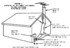
Outdoor Antenna Grounding - If an outside antenna is connected to the receiver, be sure the antenna system is grounded so as to provide some protection against voltage surges and built-up static charges. Article B10 of the National Electrical Code, ANSI/NFFA 70, provides information with regard to proper grounding of the meat and supporting structure, grounding of the load-in wire to an antenna-discharge unit, size of grounding conductors, location of antenna-discharge unit, connection to grounding electrodes, and requirements for the grounding electrode. See Figure A.
-
Nonuse Periods – The power cord of the appliance should be unplugged from the outlet when left unused for a long period of time.
-
Object and Liquid Entry – Care should be taken so that objects do not fall and liquids are not spilled into the enclosure through openings.
-
Damage Requiring Service - The appliance should be serviced by qualified service personnel when: A. The power-supply cord or the plug has been damaged;
B. Objects have fallen, or liquid has been spilled into the appliance; or
C. The appliance has been exposed to rain; or
D. The appliance does not appear to operate normally or exhibits a marked change in performance; or
E. The appliance has been dropped, or the enclosure damaged.
- Servicing - The user should not attempt to service the appliance beyond that described in the operating instructions. All other servicing should be referred to qualified service personnel.
ENGLISH DEUTSCH FRANÇAIS ESPAÑOL NEDERLANDS SVENSKA
NOTE ON USE / HINWEISE ZUM GEBRAUCH / OBSERVATIONS RELATIVES A L'UTILISATION / NOTAS SOBRE EL USO / ALVORENS TE GEBRUIKEN / OBSERVERA
- Avoid high temperatures.
Also for sufficient heat resistance when installed on a rack.
• Handle the sawer sore carefully.
- Keep the sat tree from moisture, water, and dust
- Undog the power card when not using the set for long periods of time.
* Ifor sets with ventilation hoicst
• Do not let insecticides, benzene, and thinner come in contact with the set.
- Never disassemble or modify the set in any
- The ventilation should not be impeded by covering the ventilation openings with items, such as newspapers, table-cloths, curtains, etc.
- No naked flame sources, such as lighted candles, should be placed on the apparatus.
- Please be care the environmental aspects of battery disposal
• The apparatus shall not be exposed to dripping or splashing for use. - No objects filled with clouds, such as vases, shall be placed on the apparatus.
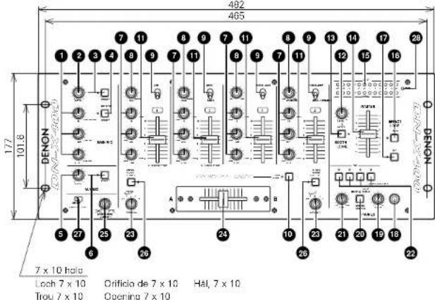
FRONT PANEL DIAGRAM / VORDERES BEDIENFELD-SCHEMA / SCHEMA DU PANNEAU AVANT / DIAGRAMA DEL PANEL FRONTAL / OVERZICHT VAN VOORPANEEL / FRONTPANELEN
text_image
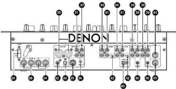
482 465 177 101.6 DENON LOCH 7 x 10 Orificio de 7 x 10 Hal, 7 x 10 Trou 7 x 10 Opening 7 x 10REAR PANEL DIAGRAM / HINTERES ANSCHLUSSFELD-SCHEMA / SCHEMA DU PANNEAU ARRIERE / DIAGRAMA DEL PANEL POSTERIOR / OVERZICHT VAN ACHTERPANEEL / BAKPANELEN
text_image
DENON 29 38 34 32 33 35 36 42 43 40 45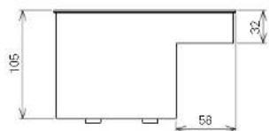
text_image
105 58 32Unit: mm Gerät: mm Unité: mm Unidad: mm Toestel: mm Erhot: mm
• DECLARATION OF CONFORMITY
We declare under our sole responsibility that this product, to which this declaration relates, is in conformity with the following standards: EN60065, EN55013, EN55020, EN61000-3-2 and EN61000-3-3. Following the provisions of 73/23/EEC, 89/336/EEC and 93/68/EEC Directive.
| 1 | Main features | 5 |
| 2 | Installation | 5 |
| 3 | Part names and functions | 5, 6 |
| 4 | Connections | 7 |
| 5 | Fader start | 8 |
| 6 | Track mark......9 |
| 7 | PFL (Pre Fader Level)......9 |
| 8 | Replacing the crossfader......9 |
| 9 | Specifications......9 |
- ACCESSORIES
Please check to make sure the following items are included with the main unit in the carton:
① Operating instructions
② Connection cords (3.5 mm stereo mini cord) ....2
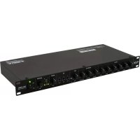
1 MAIN FEATURES
CONGRATULATIONS! You have purchased the DENON DN-X400 DJ mixer from DENON.
1. CH. Fader and Crossfader start
The CD player can be started or stopped simply by increasing or decreasing the level of the CH fader or by using the cross fader left to right or right to left. (This function can only be used when the DENON CD players DN-1800F, DN-2100F or DN-2600F is connected to the DN-X400.)
2. Digital outputs
The DN-X400 allows you to record directly to CD-R, MiniDisc or a hard disk device through it's exclusive coaxial and optical digital outputs. The digital outputs maintain a constant 16 bit / 44.1 kHz signal.
3. Track mark
Track numbers can be added at any position during recording onto a digital recorder using the DN-X400's digital outputs.
4. Enhanced input/output terminals (Analog)
8 Line, 2 Phono, 2 microphone systems, 2 Main outputs, Booth/Zone output, Sub woofer output and Rec output are provided independently. Effect input terminals are also provided for a external effects processor.
2 INSTALLATION
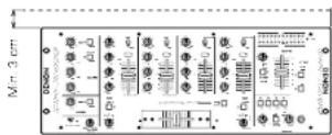
When the DN-X400 is mounted inside a coffin or DJ booth, we recommend leaving a 3 cm blank space above the mixer if possible.
5. 3-Band equalizer/Gain
Bass, Mid, Treble and Gain controls are available on every input channel.
6. Crossfader contour
This feature allows adjusting the "shape" of the Crossfader response from a gentle curve for smooth, long running fades, to the steep pitch required for top performance cut and scratch effects.
7. Mic post
This feature will pass the Main Mic signal into the Booth/Zone, Rec output and Digital output signal path. In the OFF mode, the Main Mic signal will not be routed through the above outputs.
8. PFL (Pre Fader Level)
This feature provides a means to adjust the input level gain of each channel to avoid over loading. By making this adjustment in advance will insure a smooth transition between cross fades or channel fades.
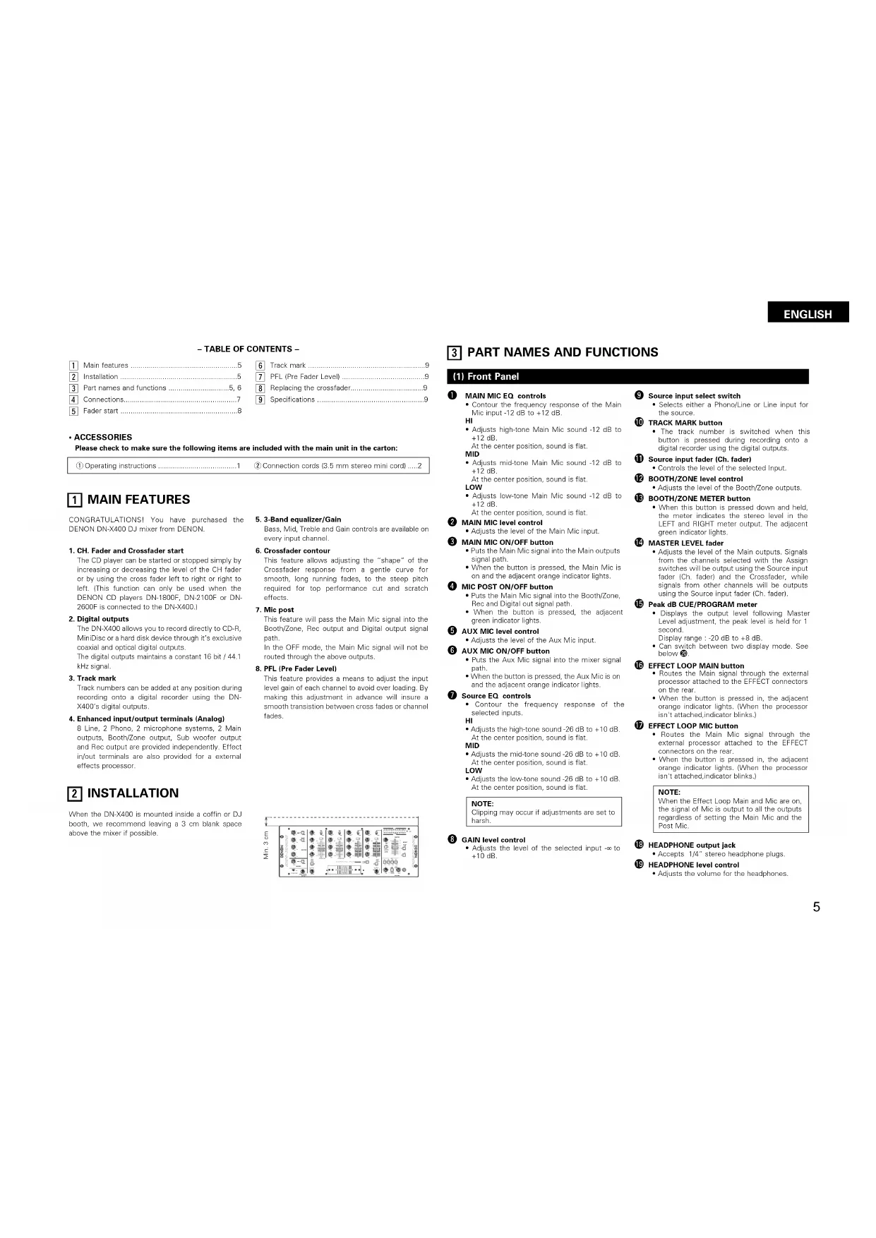
3 PART NAMES AND FUNCTIONS
(1) Front Panel
① MAIN MIC EQ controls
- Contour the frequency response of the Main Mic input -12 dB to +12 dB.
HI
- Adjusts high-tone Main Mic sound -12 dB to +12 dB.
At the center position, sound is flat.
MID
- Adjusts mid-tone Main Mic sound -12 dB to +12 dB.
At the center position, sound is flat.
LOW
- Adjusts low-tone Main Mic sound -12 dB to +12 dB.
At the center position, sound is flat.
② MAIN MIC level control
- Adjusts the level of the Main Mic input.
③ MAIN MIC ON/OFF button
- Puts the Main Mic signal into the Main outputs signal path.
- When the button is pressed, the Main Mic is on and the adjacent orange indicator lights.
4 MIC POST ON/OFF button
- Puts the Main Mic signal into the Booth/Zone, Rec and Digital out signal path.
- When the button is pressed, the adjacent green indicator lights.
⑤ AUX MIC level control
- Adjusts the level of the Aux Mic input.
6 AUX MIC ON/OFF button
- Puts the Aux Mic signal into the mixer signal path.
- When the button is pressed, the Aux Mic is on and the adjacent orange indicator lights.
7 Source EQ controls
- Contour the frequency response of the selected inputs.
HI
- Adjusts the high-tone sound -26 dB to +10 dB. At the center position, sound is flat.
MID
- Adjusts the mid-tone sound -26 dB to +10 dB. At the center position, sound is flat.
LOW
- Adjusts the low-tone sound -26 dB to +10 dB. At the center position, sound is flat.
NOTE:
Clipping may occur if adjustments are set to harsh.
8 GAIN level control
- Adjusts the level of the selected input to +10dB .
⑨ Source input select switch
- Selects either a Phono/Line or Line input for the source.
10 TRACK MARK button
- The track number is switched when this button is pressed during recording onto a digital recorder using the digital outputs.
⑪ Source input fader (Ch. fader)
- Controls the level of the selected input.
12 BOOTH/ZONE level control
- Adjusts the level of the Booth/Zone outputs
13 BOOTH/ZONE METER button
- When this button is pressed down and held, the meter indicates the stereo level in the LEFT and RIGHT meter output. The adjacent green indicator lights.
14 MASTER LEVEL fader
- Adjusts the level of the Main outputs. Signals from the channels selected with the Assign switches will be output using the Source input fader (Ch. fader) and the Crossfader, while signals from other channels will be outputs using the Source input fader (Ch. fader).
15 Peak dB CUE/PROGRAM meter
- Displays the output level following Master Level adjustment, the peak level is held for 1 second.
Display range : -20 dB to +8 dB
- Can switch between two display mode. See below ①.
16 EFFECT LOOP MAIN button
- Routes the Main signal through the external processor attached to the EFFECT connectors
on the rear.
- When the button is pressed in, the adjacent orange indicator lights. (When the processor isn't attached, indicator blinks.)
17 EFFECT LOOP MIC button
- Routes the Main Mic signal through the external processor attached to the EFFECT connectors on the rear.
- When the button is pressed in, the adjacent orange indicator lights. (When the processor isn't attached, indicator blinks.)
NOTE:
When the Effect Loop Main and Mic are on, the signal of Mic is output to all the outputs regardless of setting the Main Mic and the Post Mic.
13 HEADPHONE output jack
- Accepts 1/4" stereo headphone plugs.
19 HEADPHONE level control
- Adjusts the volume for the headphones.
ENGLISH
20 HEADPHONE mode button
- In the STEREO mode, this button feeds STEREO Program and Cue to both earcups, in the MONO mode, the Headphone circuit provides MONO Cue to the left car and MONO Program to the right.
- In the STEREO mode, the meter indicates the stereo level in the LEFT and RIGHT Main Outputs. In the MONO mode, mono CUE level is displayed on the Left meter and mono PROGRAM level is displayed on the Right meter.
- In the MONO mode, the adjacent green indicator lights.
21 HEADPHONE PAN control
- Serves two purposes... In the STEREO mode it changes the relative levels of the Cue and Program mixed together in both earcups. In the MONO mode it changes the balance between the Mono Cue in the left ear cup and the Mono Program in the right.
22 CUE buttons
- Pressing in any or all of the CUE buttons routes the respective Source to the Headphone and Meter Cue sections. Pressing multiple buttons makes it possible to derive mixed sound from the selected sources. The adjacent red indicator illuminates when the button is depressed.
23 CROSSFADE ASSIGN A. B switches
- Assigns the Crossfader to any of the four Input Channels and Off.
OFF
Select when not using the crossfader.
1 to 4
Select what channels (CH-1 to CH-4) to assign to A and B.
Channels not assigned to A or B are output without passing through the crossfader.
24 CROSSFADER
- Controls the relative output level from the summed A and B Mixes. When the fader is at its far left, only the A Mix is heard from the Outputs. As the fader is moved toward the right, the amount of B Mix is increased and the amount of A Mix is decreased. When the fader is centered, equal amounts of A and B Mixes are routed to the Outputs. Fully right is all B Mix at the Outputs.
25 CROSSFADER CONTOUR control
- Allows adjusting the "shape" of the Crossfader response from a gentle curve for smooth, long running fades, to the steep pitch required for top performance cut and scratch effects.
26 CROSSFADER START A, B buttons
- The function to start the performance of CD Player with Crossfader automatically is turned on/off.
- When the button is pressed in, the Crossfader Start is on and the adjacent orange indicator lights.
27 CH. FADER START switches
- This function will start the performance of CD Player with Ch. fader automatically is turned on/off.
28 POWER indicator
- When the green indicator is lit, the DN-X400 is ready to go.
(2) Rear Panel
29 POWER switch
- Press the switch to turn the power on.
30 MAIN OUT (BALANCED) connectors
• These XLR type connectors provide a balanced line level output.
- Connect these connectors to the balanced analog input connectors on an amplifier or console.
- Pin layout 1. Common 2. Hot 3. Cold - Applicable connector:
Cannon XLR-3-31 or equivalent.
NOTE:
Do not short-circuit the hot or cold pin with the common pin.
31 MAIN OUT (UNBALANCED) jacks
- This stereo pair of RCA jacks provide a unbalanced line level output.
- Connect these jacks to the unbalanced analog input jacks on an amplifier or console.
32 DIGITAL OUT (COAXIAL) Jack
• These RCA jacks provide a digital output data. The signal is unaffected by the Master Level fader.
• We recommend using a 75Ω/ohm RCA cord for best digital transfer. (available from any audio/video retailer)
33 DIGITAL OUT (OPTICAL) jack
• The signal is unaffected by the Master Level fader
34 BOOTH/ZONE OUT jacks
- These 1/4" jacks provide a balanced line level output with independent front panel Booth/Zone Level controls and are not affected by the Master Level control.
- Connect these jacks to the balanced analog input jacks on an amplifier or console.
35 SUBWOOFER output jack
- This 1/4" mono jacks provide a mono line level output of Main Out. The signal is affected by the Master Level fader.
- Connect this jacks to the subwoofer input jack on an amplifier.
36 SUBWOOFER frequency control
- Adjusts the cut-off frequency of the low pass filter 40 Hz to 200 Hz.
- The low adjustment, will effect the Subwoofer output.
37 REC OUT jacks
- This stereo pair of RCA jacks provide a line level output. The signal is unaffected by the Master Level fader.
- It is intended for use with a tape recorder, but is not restricted to that purpose.
38 EFFECT jacks
- These 1/4" stereo jacks allow stereo external processing of the Program signal.
• These are switching jacks — always complete the loop when connecting a send and return, or no sound will be heard.
39 LINE 1, 2, 3, 4, 6, 8 input jacks
• These stereo pairs of unbalanced RCA jacks are inputs for any line level device.
40 Ch 1,2 FADER output jacks
- Connect these jacks to the Fader input jacks of the DN-1800F, the DN-2100F and the DN-2600F using the 3.5 mm stereo mini cord.
41 PHONO 1, 2 / LINE 5, 7 input jacks
• These stereo pairs of unbalanced RCA jacks are Inputs for a Phono (RIAA) stage for magnetic (MM) cartridges or a Line stage suitable for any device, such as a CD player.
42 PHONO 1, 2 / LINE 5, 7 switches
• These switches change the Input from Phono to a Line level inputs.
- These switches set a Line level inputs when Turntable is not connected.
43 Phone Ground screw
- This screws provide a place to connect the ground wire from a turntable.
This terminal is exclusively for a turntable grounding and not a safety earth ground.
44 MAIN MIC input jack
- Accepts a balanced microphone with 1/4" jacks.
45 AUX MIC input jack
- Accepts a balanced microphone with 1/4^ jacks.
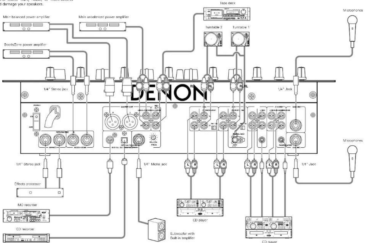
4 CONNECTIONS
Refer to the Connection Diagram below.
- Make certain AC power is off while making connections.
- Quality cables make a big difference in fidelity and punch. Use high-quality, audio cables.
-
Do not use excessively long cables. Be sure plugs and jacks are securely fastened. Loose connections cause hum, noise, or intermittents that could damage your speakers.
-
Connect all stereo input sources. Then connect any effects into the stereo Effect, if used. Connect your Microphonels and monitor headphones. Make sure all faders are at "zero" and the unit is off. Take care to connect only one cable at a time, pay attention to L and R position of jacks, on both the DN-X400 and outboard gear.
-
Connect the stereo outputs to the power amplifier(s) and/or tape deck(s) and/or MD recorder(s) and/or CD recorder(s). Plug the DN-X400 into AC power outlet.
NOTE:
Always switch on your audio input sources such as CD players first, then your mixer, and finally any amplifiers. When turning off, always reverse this operation by turning off amplifiers, then your mixer, and then input units.
flowchart
graph TD
    A["Main balanced power amplifier"] --> B["Booth/Zone power amplifier"]
    B --> C["1/4" Stereo jack"]
    C --> D["Effects processor"]
    D --> E["MD recorder"]
    E --> F["CD recorder"]
    F --> G["Subwoofer with Built-in amplifier"]
    G --> H["CD player"]
    H --> I["1/4" Jack"]
    I --> J["Microphones"]
    K["Tone deck"] --> L["Turntable 2"]
    K --> M["Turntable 1"]
    N["1/4" Mono jack"] --> O["L R"]
    N --> P["L R"]
    Q["1/4" Jack"] --> R["L R"]
    Q --> S["L R"]
    T["1/4" Stereo jack"] --> U["RFP/AC/CC/DC"]
    T --> V["RECO/OUT"]
    W["1/4" Mono jack"] --> X["BL/RL"]
    Y["1/4" Jack"] --> Z["BL/RL"]
ENGLISH
5 FADER START
If the separately sold DN-1800F, DN-2100F and DN-2600F players are connected to CH-1 or CH-2, they can be started using the source input fader ICh. faderl or Crossfader, as long as the 3.5 mm stereo mini cords have been connected.
text_image
CH1 Fader jack CH2 Fader jack 3.5 mm stereo mini cord 3.5 mm stereo mini cord CD1 Fader jack CD2 Fader jack DN-X400 DN-1800FChannel Fader Start
| 1 | Turn on the Ch. fader start switch. |
| 2 | Move the source input fader (Ch. fader) of CH-1 or CH-2 control all the way to the bottom. |
| 3 | DN-1800F Set the cue point on either drive. DN-2100F and DN-2600F Set the A-1 or A-2 point on either drive. |
| 4 | When you want to start the player, move up the source input fader ICh. faderl and the CD player will begin playing. |
NOTES:
| • Channels selected with the Crossfader Assign A, B switches and the Crossfader Start A, B buttons cannot be started with the source input fader (Ch. fader). |
| • Ch. Fader Start and Cross Fader Start for the same source will not operate simultaneously. You must select from either one. If both Ch. Fader and Cross Fader switches are ON, priority will be the cross fader. |
Crossfader Start
| 1 | Using the Crossfader Assign A. B switches, select the channel (CH-1 or CH-2) that the CD player is connected. |
| 2 | Press the Crossfader Start A. B buttons of the channel connected to the CD player to be controlled. |
| 3 | Slide the Crossfader all the way in direction opposite the source you want to start. In the following example, startup is done with the CD player connected to CH-1 set to Assign A. )A B |
| 4 | DN-1800FSat the bus point on the left drive.DN-2100F and DN-2600FSat the A-1 or A-2 point on the left drive. |
| 5 | Use the Crossfader Contour control to control the cross fader startup curve. |
| 6 | When the Crossfader is slid in the opposite direction as in "1", CD player play will begin.A B |
6 TRACK MARK
- CD category digital signals are output from the DN-X400's digital outputs. Track numbers can be added at any position during recording of these signals onto a digital recorder.
- Connect the DN-X400's digital outputs to the digital recorder. (Refer to 4 CONNECTIONS on page 7.)
| 1 | Start recording on the digital recorder. |
| 2 | Press the TRACK MARK button.• The output signal's track number changes and the green indicator lights for 4 seconds.[IMAGE] |
NOTE:
During the 4 seconds in which the track number is being changed, the track number cannot be changed again.
7 PFL (Pre Fader Level)
- Press the HEADPHONE mode button.
- Press the CUE button that you wish to monitor 1\~4 (make sure your source is playing).
- Turn the blue GAIN level knob until the L/CUE (top) meters peak at the 0 dB level.
- Perform your mix using the cross fader or channel fader at your desire.
- For proper operation, your channel levels should always be set to or left on reference line 8.
- This adjustment can be made even if the channel lader is set to zero level.
NOTES:
8 REPLACING THE CROSSFADER
The Crossfader may be removed without any disassembly of the DN-X400 itself.
- Remove the two Ⓐ outer screws attaching the crossfader assembly to the front panel.
- Pull the Crossfader Assembly forward and unplug the ribbon from the connector on the panel board.
- Install the replacement assembly by reversing the above instructions.
text_image
Technical diagram showing a device connected to an electronic board with labeled components A and B, including a connector pin.9 SPECIFICATIONS
■GENERAL
Dimensions: 482 (W) x 105 (H) x 177 (D) mm (without feet)
Installation: 19-inch rack mountable 4U
Mass: 5.5 kg
Power supply: 120 V AC ±10%, 60 Hz (U. S. A. and Canada models)
230 V AC ±10%, 50 Hz (European models)
Power consumption: 26 W
Environmental conditions: Operational temperature: 5 to 35°C (41 to 95°F)
Operational humidity: 25 to 85% (no condensation)
Storage temperature. 20 to 60°C (4 to 140°F)
■ AUDIO SECTION
Input Sensitivity & Impedance:
| Main Mic | 54 dBV (2.0 mV) | 10 kΩ/kohms |
| Aux Mic | -60 dBV (1.0 mV) | 10 kΩ/kohms |
| Effect (Return) | -10 dBV (316 mV) | 50 kΩ/kohms |
| 2-Phono | -50 dBV (3.0 mV) | 50 kΩ/kohms |
| 8-Line | -14 dBV (200 mV) | 50 kΩ/kohms |
| Output level & Impedance: | ||
| Main (Balanced) | 4 dBm (1.23 V) | 600 Ω/ohms load |
| Main (Unbalanced) | 0 dBV (1.0V) | 1 kΩ/kohms |
| Booth/Zone (Balanced) | 4 dBm (1.23 V) | 600 Ω/ohms load |
| Rec (RCA) | -10 dBV (316 mV) | 1 kΩ/kohms |
| Effect (Send) | -10 dBV (316 mV) | 1 kΩ/kohms |
| Subwoofer | -2 dBV (800 mV) | 1 kΩ/kohms |
| Headphone | -4 dBV (631 mV) | 150 Ω/ohms I33 Ω/ohms load |
Frequency Response:
| Line 20 to 20 kHz ±2 dB | |
| Phono | 20 to 20 kHz RIAA ±2 dB |
| Mic | 20 to 20 kHz ±2 dB |
Signal to Noise ratio:
| Line 80 dB | 0 dBm, 1 kHz, EQ flat | |
| Phono | 75 dB | 0 dBm, 1 kHz, EQ flat |
| Main Mic | 65 dB | 0 dBm, 1 kHz, EQ flat |
Total harmonic distortion rate:
| Line Below 0.05% | |
| Phono | Below 0.05% |
| Cross talk: | Over 70 dB |
| Channel equalizer: | |
| Hi | +10 dB, -26 dB (13 kHz) |
| Mid | +10 dB, -26 dB (1 kHz) |
| Low | +10 dB, -26 dB (70 Hz) |
| Microphone equalizer: | |
| Hi | +12 dB, -12 dB (10 kHz) |
| Mid | +12 dB, -12 dB (1 kHz) |
| Low | +12 dB, -12 dB (100 Hz) |
Digital output (COAXIAL):
| Signal format | IEC958 Type II |
| Output level | 0.5 Vp-p 75 Ω/chme |
| Output signal level | -6 dB |
Digital output (OPTICAL):
| Signal format | IEC958 Type II |
* Specifications and design are subject to change without notice for purpose of improvement.
ENGLISH
DEUTSCH
- INHALT -
8. Vor-Fader-Pegel PFL (Pre Fader Level)
(DIGITAL OUT (COAIAL))
33 DIGITALAUSGANGS-Buchse (DIGITAL OUT (OPTICAL))
7 VOR-FADER-PEGEL PFL (Pre Fader Level)
text_image
Technical diagram showing a device with labeled components and an arrow indicating connection to a base plate.9 TECHNISCHE DAREN
■ ALLGEMEIN
① Commandes MAIN MIC EQ
③ Touche MAIN MIC ON/OFF
32 Prise DIGITAL OUT (COAXIAL)
33 Prise DIGITAL OUT (OPTICAL)
text_image
Technical diagram showing a device with labeled components and an arrow indicating connection to a base plate.9 SPECIFICATIONS
■GENERAL
Dimensions: 482 (L) x 105 (H) x 177 (P) mm (sans les pieds)
- Conector applicable:
Cannon XLR-3-31 o equivalente.
NOTA:
text_image
Technical diagram showing a device with labeled components and an arrow indicating connection to a base plate.9 ESPECIFICACIONES
■GENERAL
| Linea | 80 dB | 0 dBm, 1 kHz, EQ plano |
| Fono | 75 dB | 0 dBm, 1 kHz, EQ plano |
| Micrófono principal | 65 dB | 0 dBm, 1 kHz, EQ plano |
text_image
Technical diagram showing a device with labeled components and an arrow indicating connection to a base plate.NEDERLANDS
| Line | 80 dB | 0 dBm, 1 kHz, EQ vlak |
| Phono | 75 dB | 0 dBm, 1 kHz, EQ vlak |
| Mic | 65 dB | 0 dBm, 1 kHz, EQ vlak |
③ MAIN ON/OFF-tangent
text_image
Technical diagram showing a device with labeled components and an arrow indicating connection to a base plate.9 SPECIFICATIONER
Total harmonisk distorsion:
Line Under 0.05 %
Phono Under 0.05 %
Overhörning: Over 70 dB
Equalizer:
HI +10 dB, -26 dB (13 kHz)
Mid +10 dB, -26 dB (1 kHz)
Low +10 dB, -26 dB (70 Hz)
Mikrofon-equalizer:
Hi +12 dB, -12 dB (10 kHz)
Mid +12 dB, -12 dB (1 kHz)
Low +12 dB, -12 dB (100 Hz)
Printed in Japan 511 3835 002