MMX82 UFX - Mixer Monacor - Free user manual and instructions
Find the device manual for free MMX82 UFX Monacor in PDF.
User questions about MMX82 UFX Monacor
0 question about this device. Answer the ones you know or ask your own.
Ask a new question about this device
Download the instructions for your Mixer in PDF format for free! Find your manual MMX82 UFX - Monacor and take your electronic device back in hand. On this page are published all the documents necessary for the use of your device. MMX82 UFX by Monacor.
USER MANUAL MMX82 UFX Monacor
Before switching on ...
We wish you much pleasure with your new "img Stage Line" unit. Please read these operating instructions carefully prior to operating the unit. Thus, you will get to know all functions of the unit, operating errors will be prevented, and yourself and the unit will be protected against any damage caused by improper use. Please keep the operating instructions for later use.
The English text starts on page 10.
F Avant toute installation ...
Line (Mono-Kanal): .1 mV/10 kΩ;
6,3-mm-Klinke, sym.
Line (Stereo-Kanal): .10 mV/10 kΩ;
6,3-mm-Klinke, sym
1 = Masse
2 = Signal +
3 = Signal -
T = Signal
S = Masse
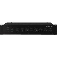
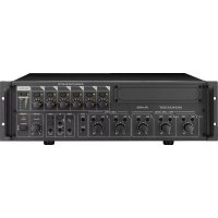
1 Operating Elements and Connections 10
1.1 Input channels 10
1.2 Output panel 10
1.3 Rear panel 11
2 Safety Notes 11
3 Applications 11
4 Connecting Units 12
4.1 Audio sources 12
4.1.1 Microphones 12
4.1.2 Line audio sources 12
4.2 Effect units 12
4.2.1 Inserting effect units 12
4.2.2. Using send ways 12
4.3 Recorder 12
4.4 Connecting a control monitor system and headphones 12
4.5 Monitor system for the musicians .12
4.6 Amplifier for PA applications in halls . . 12
4.7. Operation with a computer 12
4.8 Outputs of the subgroups 13
4.9 Foot pedal for the effect processor . . . 13
4.10 Power supply 13
5 Operation 13
5.1 Switching on and off 13
5.2 Level control of the input channels 13
5.3 Mixing input signals 13
5.4 Adjusting the monitor send way 13
5.5 Adding effects 14
5.5.1 Using the internal effect processor . . 14
5.5.2 External effect unit 14
5.5.3 Separate effect unit for the subgroups 14
5.6 Monitoring via headphones and a control monitor system 15
6 Specifications 15
6.1 Pin configuration of XLR and 6.3 mm plugs 15
1.1 Input channels
Fig. 1 Mono input channel CH 1; the other mono input channels are identical.
Fig. 2 Stereo input channel CH 9 /10; with the exception of the button of item 19, the second stereo input channel is identical.
1 Channel fader to adjust the volume of the channel and to fade in/fade out the channel signal
2 Button SOLO to monitor the selected channel via the headphones connected to the jack PHONES (52) and via a monitor system connected to the jacks BOOTH OUT (53):
either for pre-fader listening when the button PFL/AFL (40) is disengaged
or for controlling the overall channel adjustment after the channel fader when the button PFL/AFL is pressed
When the button SOLO is pressed, the corresponding LED PEAK (5) will light permanently and the level indicators (38) will indicate the corresponding channel signal.
3 Button L-R: When the button is pressed, the channel signal will be added to the sum channels MASTER. With the control PAN (7) or BAL (8), the signal can be added to the right or to the left channel only or to both channels.
4 Button 1-2: When the button is pressed, the channel signal will be added to the subgroups SUB 1 and SUB 2. With the control PAN (7) or BAL (8), the signal can be added to group SUB 1 or SUB 2 only or to both groups.
5 LED PEAK: When the button SOLO (2) is pressed, the LED PEAK will light permanently. When the button SOLO disengaged, the LED PEAK will light up briefly to indicate that the maximum undistorted signal level has been reached. If it lights up longer, the channel is overloaded. In this case, turn back the control GAIN (20) accordingly.
6 Button MUTE (with LED indicator) to mute the channel
7 Panorama control PAN to place the mono signal in the stereo sound When the button 1-2 (4) is pressed, the control PAN can be used to assign the channel signal to the subgroups.
8 Balance control When the button 1-2 (4) is pressed, the balance control can be used to assign the channel signal to the subgroups.
9 Control AUX SEND 2/FX to add the channel signal to send way 2 (post-fader); this send way is also used as an effect way for the internal effect processor
10 Selector button PRE for send way 1 disengaged: signal picked-up post-fader The channel signal is fed to the send way after the fader (1).
pressed: signal picked up pre-fader The channel signal is fed to the send way ahead of the fader.
11 Control AUX SEND 1/MON to add the channel signal to send way 1
12 Equalizer control LOW 80 Hz for the bass frequencies: ±15 dB at 80 Hz
13 Equalizer control MID for the mid-frequencies: ±15 dB at 100 Hz -8 kHz
14 Equalizer control MID 500Hz for the mid-frequencies at 500Hz : ± 15 dB
15 Control MID FREQ to adjust the filter frequency (100Hz - 8kHz) for equalizer control in the midrange
16 Equalizer control MID 3kHz for the mid-frequencies at 3kHz ± 15 dB
17 Equalizer control HIGH 12 kHz for the high frequencies: ±15 dB at 12 kHz
18 Button for the low cut filter (high pass filter):
When the button is pressed, unwanted signal parts below 75Hz (e.g. impact noise) will be suppressed.
19 Channel CH 9/10: Button +4 / - 10 for matching the level of units with low output level; when the button is pressed, the input level will be boosted
Channel CH 11/12:
Button LINE/OPT to switch the channel input disengaged: input = jacks LINE (21)
pressed: input = signal of an additional module (e.g. MP3 player) which is installed in the upper right section instead of the cover panel
20 Control GAIN to adjust the input amplification
21 Input LINE (6.3 mm jack, bal.) to connect a signal source with line output level (e.g. musical instrument, CD/MP3 player)
Note with regard to the stereo channels: When connecting a mono unit, only use the jack L. The signal will then be internally sent to the right and left channels.
22 Input MIC to connect a microphone (XLR jack, bal.)
A phantom power can be activated for all microphone inputs, item 49.
23 Input and output jacks (RCA) TAPE for a recorder
The sum signal is available at the jacks OUT [after the faders MASTER (34)].
When the button TAPE/USB TO MIX (41) is pressed, the signal of the jacks IN will be added to the sum signal ahead of the faders MASTER.
1.2 Output panel
24 Faders for the subgroups 1 and 2
25 Buttons MUTE (with LED indicator) to mute the subgroups
26 Assign buttons SUB ASSIGN TO MASTER to forward the subgroup signals to the left or/ and right sum channel
27 Level control FX RETURN for the effect signal of the internal effect processor or for the signal at the input FX RETURN (57)
Use the level control to add the signal to the sum channels MASTER.
28 Level control AUX SEND MASTER 2 / FX for the total signal of send way 2 that is sent to the internal effect processor and to the output AUX SEND 2 (55)
29 Button SOLO - one for send way 1 and one for send way 2 - to monitor the send way via the headphones connected to the jack PHONES (52) and via a monitor system connected to the jacks BOOTH OUT (53)
30 Level control AUX SEND MASTER 1/MON for the total signal of send way 1 that is available at the output AUX SEND 1 (55)
31 Level control AUX RTN to add the signals at the input AUX RTN (56) to the sum channels MASTER [button MASTER SUB 1-2 (39) disengaged] or to the subgroup channels [button pressed]
32 Buttons BOOTH to select the signals that are to be monitored via the headphone jack PHONES (52) and the output BOOTH OUT (53) and that are to be indicated by the level indicators (38):
- button MASTER MIX for the output signals of the sum channels MASTER
- button CD / USB / TAPE for the input signals of the jacks TAPE IN (23) and of the USB port (45)
- button SUB 1-2 for the signals of the subgroups 1 and 2
Notes
- If multiple buttons are pressed, the mixed signal of the corresponding sources will be monitored and indicated.
- The monitor signals selected by means of the buttons SOLO (2, 29) will take priority: If a button SOLO is pressed, the corresponding signals will be monitored and indicated instead of the signals that may have been selected by means of the buttons BOOTH.
33 Volume control BOOTH / PHONES for the headache output PHONES (52) and the output BOOTH OUT (53)
34 Faders for the sum channels
35 LED indicator PHANTOM 48V: lights up when phantom power for the inputs MIC (22) has been activated
36 LED POWER ON
37 Control RETURN TO AUX 1 to add the signals of the internal effect processor or the signals of the jacks FX RTN (57) to send way 1
38 Level indicators, indicate the level of the signal that has been selected to be monitored via the headphone output PHONES (52) and the output BOOTH OUT (53):
- the signals of the input channels / send ways for which the button SOLO (2, 29) has been pressed
- if none of the buttons SOLO has been pressed, the monitoring signal that has been selected by means of the button BOOTH (32)
39 Assign button MASTER / SUB 1-2 to forward the signals of the input AUX RTN (56) to the sum channels MASTER (button disengaged) or to the subgroup channels (button pressed)
40 Button PFL /AFL (with LED indicator beneath the button):
button disengaged = PFL (pre-fader listening) The input channels for which the button SOLO (2) is pressed will be monitored ahead of the control PAN (7) or BAL (8) and the fader (1); the send ways for which the button SOLO (29) is pressed will be monitored ahead of the control AUX SEND 28,30.
button pressed = AFL (after-fader listening) The input channels for which the button SOLO is pressed will be monitored after the control PAN or BAL and the fader; the send ways for which the button SOLO is pressed, will be monitored after the control AUX SEND.
41 Button TAPE / USB TO MIX: When the button is pressed, the input signals of the jacks TAPE IN (23) and of the USB port (45) will be sent to the sum channels MASTER.
42 Button MUTE to activate/deactivate a selected effect When the effect is deactivated, the LED PEAK above the button will light permanently. When the effect is activated, the LED will only light up briefly in case the effect processor is overloaded.
43 Knob FX SELECT to select an effect: Turn the knob until the appropriate effect number starts flashing on the display. Then briefly press the knob to confirm your selection.
44 Display EFFECT to show the effect number selected
45 USB port (type B) to connect a computer; can simultaneously be used as an output (digital output of the sum signal) and as an input [feed-in of audio data] (full-duplex mode)
1.3 Rear panel
46 Mains jack for connection to a mains socket (230V /50Hz) via the mains cable supplied
47 Support for the mains fuse Always replace a blown fuse by a fuse of the same type.
48 POWER switch
49 Switch PHANTOM of the 48 V phantom power supply for all microphone inputs MIC (22); when the phantom power is activated, the LED PHANTOM 48V (35) will light up Please observe the warning notes with regard to the phantom power in chapter 4.1.1.
50 Outputs MASTER for the sum signal, e. g. to connect the amplifier for PA applications in halls
- via XLR jacks,
Left L/Right R,balanced
- via 6.3 mm jackets
Left L/Right R,unbalanced
51 Connection FOOT SWITCH (6.3 mm jack, 2 poles) for a foot pedal to activate/deactivate the internal effect processor
52 Output PHONES (6.3 mm jack) to connect stereo headphones (minimum impedance: 8Ω)
53 Output BOOTH OUT (6.3 mm jacks Left L/ Right R, unbal.) to connect a control monitor system
54 Outputs SUB OUT (6.3 mm jacks, unbal.) for subgroups 1 and 2
55 Outputs AUX SEND (6.3 mm jacks, unbal.) for send ways 1 and 2
56 Inputs AUX RTN (6.3 mm jacks Left L/Right R, unbal.), can be used as an input for an effect unit or for an additional line audio source Note: To connect a mono unit, only use the jack L. The signal will then be internally sent to the right and left channels.
57 Effect signal inputs FX RTN (6.3 mm jacks Left L/Right R, unbal.) When the inputs are connected, the input signal is sent to the sum channels and the signal way from the internal effect processor to the sum channels is interrupted.
58 Jacks CHANNEL INSERTS (6.3 mm jacks) to insert effect units (e.g. compressors) into the mono input channels CH 1 to CH 8
Plug connections:
tip = Send (output)
ring = Return (input)
sleeve = Ground
2 Safety Notes

The unit corresponds to all relevant directives of the EU and is therefore marked with
WARNING

This unit uses dangerous mains voltage. Leave servicing to skilled personnel. Do not insert anything into the air vents. Inexpert handling or modification may result in electric shock.
Please observe the following items in any case:
The unit is suitable for indoor use only. Protect it against dripping water and splash water, high air humidity and heat (admissible ambient temperature range: 0 - 40^ ).
- Do not place any vessel with liquid on the unit, e. g. a drinking glass.
- Do not operate the unit and immediately disconnect the mains plug from the socket
-
if the unit or the mains cable is visibly damaged,
-
if a defect might have occurred after the unit was dropped or suffered a similar accident, 3. if malfunctions occur.
In any case the unit must be repaired by skilled personnel.
- Never pull the mains cable to disconnect the mains plug from the socket, always seize the plug.
For cleaning only use a dry, soft cloth; never use water or chemicals.
No guarantee claims for the unit and no liability for any resulting personal damage or material damage will be accepted if the unit is used for other purposes than originally intended, if it is not correctly connected or operated, or if it is not repaired in an expert way.

If the unit is to be put out of operation definitively, take it to a local recycling plant for a disposal which is not harmful to the environment.
3 Applications
This audio mixer is designed for various PA and recording applications. It provides 8 mono and 2 stereo input channels to connect microphones (also phantom-powered) and audio sources with line output level (e.g. instruments and players). The input signals can be added to a stereo sum channel, two subgroups and two send ways. The integrated effect processor can be used to add effects. Audio mixing may be monitored by means of headphones and/or a monitor system in a separate control room.
In addition to the RCA jacks for a recorder, the mixer provides a USB audio interface for connection to a computer. This interface may be used as an output for digital recording of the audio mix and as an input for feeding in audio files.

4 Connecting Units
To avoid interfering noise, switch off the mixer or turn back /set the following controls / faders minimum prior to connecting / disconnecting:
- MASTER (34)
-BOOTH/PHONES(33) - AUX SEND MASTER 1 / MON (30) if send way 1 is used as a monitor way.
4.1 Audio sources
Since it is not possible to switch between the inputs in the mono channels, either connect the microphone input (22) or the line input (21); never connect both inputs at the same time.
4.1.1 Microphones
Connect microphones to the balanced XLR jacks MIC (22). For phantom-powered microphones, use the switch PHANTOM (49) on the rear panel to activate a joint phantom power supply of 48V for all XLR jacks. When the phantom power supply is activated, the LED PHANTOM 48V (35) lights up.
Caution: When the phantom power is activated, do not connect any microphone with unbalanced output; it may be damaged.
To prevent switching noise in the speakers and the headphones, only activate or deactivate the phantom power when the mixer has been switched off or when the corresponding controls have been set to minimum.
4.1.2 Line audio sources
Connect audio sources with line signal level (e.g. receivers of wireless microphone systems, effect units, musical instruments, players) to the 6.3mm jacks LINE (21) of the input channels. The jacks are balanced. However, to connect units with unbalanced output, use 2-pole 6.3mm plugs.
- Connect mono units to the mono channels CH 1 to CH 8.
- Connect stereo units to the stereo channels CH 9/10 and CH 11/12. To connect a mono unit to a stereo channel, only use the jack L; the mono signal will then internally be sent to the right and left channels.
If the input channels do not suffice, use the following stereo inputs to connect additional line sources:
- input AUX RTN (56)
(To connect a mono unit, only use the jack L; the mono signal will then internally be sent to the right and left channels.) - input FX RTN (57)
(When the input is connected, the signal way from the internal effect processor to the sum channels will be interrupted.) - input TAPE IN (23)
(e.g. to connect a CD player for background music during intervals)
4.2 Effect units
4.2.1 Inserting effect units
Effect units (e.g. units for audio processing such as compressors, equalizers and noise gates) may be directly inserted into the mono channels: The channel signal is decoupled after the control GAIN (20) and the low cut filter (18), is routed via the effect unit and is then returned to the channel at the same position in the signal way.
Connect the effect unit to the 6.3mm jack CHANNEL INSERT (58) of the respective channel. The plugs must be connected as follows: tip = Send (output) ring = Return (input) sleeve = Ground
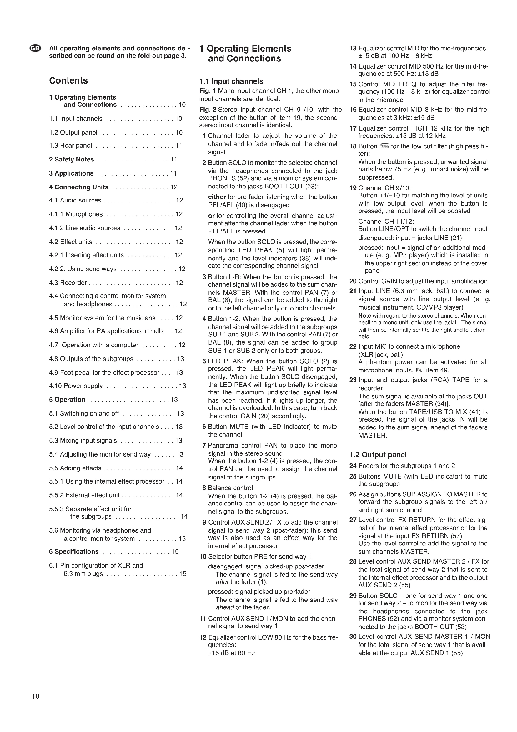
To connect effect units with separate input and output jacks, Y cables are required, e. g. MCA202 from MONACOR:
Fig. 6 Connection via Y cable MCA-202
4.2.2 Using send ways
Via send ways 1 and 2, signal parts can be decoupled from the input channels, processed by means of an effect unit (e.g. reverb unit) and returned to the mixer via the Return inputs. Normally, the signal for a send way used as an effect way is picked up post-fader, i.e. the channel signal is added to the send way after the fader (1). Thus, the effect part of a channel is always in proportion to the channel level adjusted. For each channel, the button PRE (10) can be pressed to switch send way 1 from post-fader to pre-fader. Send way 2 is preset to post-fader; this cannot be changed. Send way 2 also serves as an effect way for the internal effect processor.
1) Depending on the send way used, connect the input of the effect unit via a 6.3mm jack to the mono output AUX SEND 1 or 2 (55).
2) To return the signal coming from the effect unit, the inputs AUX RTN (56) and FX RTN (57) are available:
- When the input AUX RTN is used: Use the control AUX RTN (31) to add the effect signal to either the sum channels MASTER [button MASTER/SUB 1-2 (39) disengaged] or to the subgroup channels [button MASTER/SUB1-2pressed].
Note: To connect a mono unit, only use the jack L; the mono signal will then internally be sent to the right and left channels. - When the input FX RTN is used: Use the control FX RTN (27) to add the effect signal to the sum channels or use the control RETURN TO AUX 1 (37) to add the effect signal to send way 1.
Note: Connecting the jack L and R of this input will interrupt the signal way from the left and right channels of the internal effect processor to the sum channels.
Alternatively, feed the signals from the effect unit to the line input of an available input channel.
4.3 Recorder
A recorder can be connected to the RCA jacks TAPE (23) [L = left channel, R = right channel]:
1) For reproduction, connect the output of the unit to the jacks TAPE IN.
2) For recording, connect the input of the unit to the jacks TAPE OUT. Here, the sum signal adjusted by means of the faders MASTER (34) is available.
4.4 Connecting a control monitor system and headphones
The signals of the individual input channels, the sum signals, the subgroup signals and the input signals of the jacks TAPE IN (23) and of the USB port (45) can be monitored via headphones and/or a monitor system in a separate control room. Connect the headphones (minimum impedance: 8 Ω) to the jack PHONES (52). Connect the amplifier of the monitor system to the jacks BOOTH OUT (53); these output jacks are unbalanced.
4.5 Monitor system for the musicians
When a monitor system is used for stage PA applications, send way 1 may serve as a monitor way. Normally, the signal for the send way used as a monitor way is picked up pre-fader, i.e. the channel signal is added to the send way ahead of he fader (1). Thus, the stage monitors provide the musicians with an audio signal that has been separately mixed. For each input channel, the buttons PRE (10) can be pressed to switch send way 1 to pre-fader.
Connect the amplifier of the monitor system or of an active monitor speaker system to the mono output jack AUX SEND 1 (55).
4.6 Amplifier for PA applications in halls
The stereo sum signal is available at the outputs
MASTER (50):
XLR jacks, balanced
6.3 mm jacks, unbalanced
(L = left channel, R = right channel).
Connect the amplifier for PA applications in halls to one of the outputs. The second output may be used at the same time, e.g. for a second amplifier or to send the sum signal to an additional unit.
4.7 Operation with a computer
Via the USB port (45), audio files can be transferred in both directions between the mixer and the computer:
- When the USB port is used as an input: Use the button TAPE/USB TO MIX (41) to add data fed in via the USB port to the sum signal and to monitor the data via headphones and a control monitor system.
- When the USB port is used as an output: The USB port provides the sum signal that has been adjusted with the faders MASTER (34).
To operate the mixer with a computer, either use the audio software supplied with the operating system or audio software installed additionally. Various audio software programs for recording and reproduction are available on the Internet free of charge.
1) Start the computer and connect the USB port (45) to a USB connection on the computer.
2) The computer will recognize the switched-on mixer as a USB audio device for audio input and audio output. The required drivers (default drivers of the operating system) should be available on the computer.
Note: If not all drivers required are available on the computer, install them, e. g. by means of the original CD of the operating system. If necessary, restart the computer after installing the drivers.
3) Call up the audio program used, make the settings required for audio reproduction via the mixer or audio recording from the mixer (manual of the program). The mixer can then be operated as described in chapter 5.
If no audio recording or audio production is possible, check the system settings of the computer to find out if the USB interface has been selected for audio input or audio output.
Hint: If the mixer is connected to both a computer and to units earthed via their mains cable (e.g. amplifiers), hum interference may occur due to ground loops. To eliminate this interference, use a ground isolator (e.g. FGA-102 or FGA-202 from "img Stage Line") to connect the mixer to the corresponding unit.
4.8 Outputs of the subgroups
The subgroup signals can be added to the signal sum via the buttons SUB ASSIGN TO MASTER (26), but they are also available at the outputs SUB OUT (54). The subgroup signals may be forwarded from these outputs to another mixer or to a separate effect unit, for example.
4.9 Foot pedal for the effect processor
To activate and deactivate the internal effect processor, a foot pedal, e. g. FS-60 from MONACOR, may be connected to the 2-pole 6.3mm jack FOOT SWITCH (51).
4.10 Power supply
Use the mains cable supplied to connect the mains jack (46) to a socket (230V /50Hz)
5 Operation

Never adjust the audio system and the headphones to a very high volume. Permanent high volumes may damage your hearing! Your ear will get accustomed to high volumes which do not seem to be that high any more after some time. Therefore, do not further increase a high volume after getting used to it.
5.1 Switching on and off
1) To prevent switching noise and an excessive volume, set the following output controls to minimum prior to switching on the mixer:
- MASTER (34)
-BOOTH/PHONES(33) - AUX SEND MASTER / MON (30) if send way 1 is used as a monitor way.
2) Depending on the microphone type connected, use the switch PHANTOM (49) to activate or deactivate the 48 V phantom power (12 chapter 4.1.1).
3) Use the POWER switch (48) to switch the mixer on and off. When the mixer is switched on, the LED indicator POWER ON (36) will light up.
5.2 Level control of the input channels
The following steps merely serve as an aid; other procedures are possible.
1) First, make the following basic adjustments:
a) In all mono input channels (fig. 1), set the controls GAIN (20), the equalizer controls HIGH (17), MID (13), LOW (12) and the control PAN (7) to mid-position. Disengage the buttons
b) In all stereo input channels (fig. 2), set the equalizer controls HIGH (17), MID 3 kHz (16), MID 500 Hz (14), LOW (12) and the control BAL (8) to mid-position. Disengage the button +4 10 (19) in channel
CH 9/10, and disengage the button LINE / OPT (19) in channel CH 11/12.
c) In all input channels, turn back the controls AUX SEND 1/MON (11) and AUX SEND 2/FX (9) for the send ways to minimum.
d) In all input channels, disengage the buttons MUTE (6), 1-2 (4), L-R (3) and SOLO (2) and set the channel faders (1) to minimum.
e) On the output panel (fig. 3), disengage all buttons SOLO (29) and the button TAPE/USB TO MIX (41) and turn back the controls AUX SEND MASTER (28, 30) and the controls RETURN (27, 31, 37) to minimum.
2) Feed an audio signal to the first channel used (e. g. sing into a microphone, play a musical instrument).
3) If the signal is to be made audible via the connected amplifier for PA applications in halls, advance the fader (1) of the channel to the position "0", press the button L-R (3) and then advance the faders MASTER (34) until the signal can be heard well. However, it is also possible to monitor the signal via headphones or a control monitor system when the faders are closed, chapter 5.6.
4) Press the button SOLO (2) of the channel to switch on the monitor function for the channel; the LED PEAK (5) will light up.
5) If necessary, disengage the button PFL/AFL (40) to select the monitor mode "PFL": the LED beneath the button will light up in green and the left row of LEDs of the level indicators (38) will indicate the channel signal ahead of the fader and the control PAN (7) or BAL (8).
6) Use the level indicators for an optimum adjustment of the input amplification:
For a mono channel, adjust the control GAIN (20) so that a level of approximately 0 dB is indicated.
If the stereo channel CH 9/10 is overloaded even though the button +4 / - 10 (19) is disengaged, attenuate the level of the signal source. If the level is too low, press the button +4 / - 10 to boost the level (12 dB).
The input amplification for the stereo channel CH 11/12 is predefined and cannot be changed. If the level is not ideal, change the output level of the signal source connected.
7) Adjust the sound, using the controls HIGH (17) for the high frequencies and LOW (12) for the low frequencies (± 15dB)
For a mono channel, use the control MID FREQ (15) to adjust the mid-frequency (100 - 8000Hz) and use the control MID (13) to boost or attenuate (15 dB) it. If required, press the button _SH (18) to suppress low-frequency interference (e.g. impact noise, hum).
For a stereo channel, use the controls MID 500 Hz (14) and MID 3 kHz (16) to adjust the mid-frequencies (± 15dB)
Then check the level of the channel and, if necessary, correct the input amplification.
8) Disengage the button SOLO to switch off the monitor function for the channel. When the monitor function is switched off, the LED PEAK serves as an overload indicator with which the level of the channel can be roughly checked. If it lights permanently, attenuate the input amplification (control GAIN) or the input signal.
9) To make sure that only the channel being adjusted is audible while the signal is being reproduced via the amplifier for PA applica
tions in halls: After controlling the level of a channel, set its fader (1) to minimum or press MUTE (6) to mute the channel.
10) Repeat steps 2) to 9) for all the other input channels.
5.3 Mixing input signals
1) Define for each input channel if the channel signals are to be added to the sum channels or/ and to the subgroup channels:
- To add the signals to the sum channels.
MASTER, press the button L-R (3).
To add the signals to the channels SUB 1 and 2, press the button 1-2 (4). Use the faders SUB 1 and 2 (24) to fade in and fade out these signals or to change their volume. If required, use the jacks SUB OUT (53) to send these signals to a separate effect unit.
2) Advance the faders MASTER (34) until it is possible to adjust the mixing ratio of the audio sources in an optimum way.
3) Use the faders (1) to mix the signals of the input channels in the volume ratio desired. Always close the faders of unused channels.
4) For the mono channels, use the panorama controls PAN (7) to place the mono signals in the stereo sound. For the stereo channels, use the controls BAL (8) to adjust the balance of the stereo signals.
5) If signals are sent to the subgroups, press the corresponding buttons SUB ASSIGN TO MASTER (26) to add the subgroups to the left and right sum channels. (Usually, press the button L in channel SUB 1 and the button R in channel SUB 2). Use the faders SUB 1 and SUB 2 (24) to adjust the volume of the subgroup signals.
6) Please refer to chapter 5.5 for information on adding effects.
7) To add the input signal of the jacks TAPE IN (23) and of the USB port (45) to the signal sum, press the button TAPE / USB TO MIX (41).
Note: If, during recording via the jacks TAPE OUT or the USB port, the recording signal is fed as an input signal to the jacks TAPE IN or to the USB port, make sure that the button TAPE / USB TO MIX is not pressed; otherwise, there will be feedback.
8) Use the faders MASTER to adjust the definite volume of the sum signal; check the level indicators (38) while adjusting the volume. To make sure that the level indicators indicate the level of the sum signal, press the button MASTER MIX (32). Also make sure that all the buttons SOLO (2, 29) for the monitor function are disengaged. [If one of the buttons SOLO is pressed, the LED beneath the button PFL /AFL (40) will light up.] The red LEDs CLIP of the level indicator will light up in case of overload; close the faders MASTER accordingly.
9) To mute a channel, e. g. during an interval, press the button MUTE (6, 25). The LED beneath the button will light up.
5.4 Adjusting the monitor send way
Make sure that the monitor system for stage PA applications is connected to the jack AUX SEND 1 (55) of send way 1.
1) For the channels that are fed to the monitor way, press the button PRE (10) in order to set the position where the signal for the monitor way is picked up to pre-fader.
2) Turn up the control AUX SEND MASTER 1 / MON (30) for the total volume of the monitor mix until the monitor signal can be easily

heard via the monitor system when the subsequent adjustments are made.
3) Use the controls AUX SEND 1/MON (11) to add the channel signals to the monitor way: Turn up the controls, depending on the desired volume ratio of the channels.
4) Use the control RETURN TO AUX 1 (37) to add the effect signal of the internal effect processor to monitor way 1 or to add the signal from the jacks FX RTN (57) if a unit is connected to these jacks.
5) To monitor the monitor way via headphones or a control monitor system and to have the monitor signal indicated by the level indicators (38), press the button SOLO (29) next to the control AUX SEND MASTER 1/MON (30), chapter 5.6.
5.5 Adding effects
5.5.1 Using the internal effect processor
The internal effect processor allows for the generation of 100 different effects that can be added to the sum channels MASTER and to send way 1. Send way 2 is used as an effect way for the effect processor.
Important: The input FX RTN (57) must be available when the effect processor is used. When the two jacks are connected, the signal way of the internal effect processor to the sum channels and to send way 1 is interrupted.
1) To make sure that the subsequent effect adjustments are audible, first set the controls AUX SEND MASTER 2 / FX (28) and FX RE -TURN (27) approximately to mid-position.
2) Turn the knob FX SELECT (43) clockwise or counter-clockwise until the number of the desired effect (figure 7 Effect overview) starts flashing on the display (44). Press the knob to confirm the number: The number stops flashing; the effect is activated.
3) Use the controls AUX SEND 2/FX (9) to add the signals of the input channels to the effect way. The signal is picked up after the fader (1), i.e. the effect part of a channel is always in proportion to the channel level adjusted.
4) Use the control AUX SEND MASTER 2 / FX (28) to adjust the level of all the signals that have been added to the effect way. The signals are fed to the input of the effect processor and are also available at the jack AUX SEND 2 (55).
When the effect processor is activated, the LED PEAK above the button MUTE (42) serves as an overload indicator with which the level can be roughly checked. If the LED
PEAK lights up, turn back the control AUX SEND MASTER 2/FX accordingly.
5) Use the button FX RETURN (27) to add the effect signal to the sum channels, and if desired, use the button RETURN TO AUX 1 (37) to add the effect signal to send way 1.
6) Use a foot pedal connected to the jack FOOT SWITCH (51) and the button MUTE (42) to switch the effect processor off and on (the button will not engage). When the effect processor is switched off, the LED PEAK above the button MUTE will light up.
5.5.2 External effect unit
The effect unit must be connected via an Aux Send output and an Aux Return input (or line input of an available input channel), chapter 4.2.2.
1) To make sure that the subsequent effect adjustments are audible, set the respective output control and input control approximately to mid-position:
depending on the output used control AUX SEND MASTER 1/MON (30) or control AUX SEND MASTER 2/FX (28)
depending on the input used control AUX RTN (31) or control FX RETURN (27) or
fader (1) of the corresponding input channel
2) If the effect unit is connected to the input AUX RTN (56), use the button MASTER / SUB 1-2 (39) to define if the effect signal is to be sent to the sum channels (button disengaged) or to the subgroup channels (button pressed).
3) Depending on the send way used as an effect way, use the controls AUX SEND 1 / MON (11) or the controls AUX SEND 2 / FX (9) to add the channel signals to the effect way. With these controls, the desired effect intensity can be separately adjusted for each channel.
If send way 1 is used as an effect way, the buttons PRE (10) must be disengaged (setting post-fader).
Note: If the effect unit is connected to the line input of an input channel, turn back the control AUX SEND 1 or 2 of the respective channel to minimum; otherwise, there will be feedback.
4) Use the appropriate output controls AUX SEND (28, 30) to adjust the level for the output signal of the effect way so that the effect unit is not overloaded.
Use the button SOLO (29) next to the control AUX SEND to monitor the effect way via
headphones or a control monitor system and to check it by means of the level indicators (38), chapter 5.6.
5) Use the appropriate input control to add the signal coming from the effect unit; the control allows for the joint adjustment of the effect intensity for all channels:
If the effect unit is connected to the input AUX RETURN (56), use the control AUX RTN (31) to add the effect signal to the sum channels or to the subgroup channels (depending on the position of the button MASTER / SUB1-2).
If the effect unit is connected to the input FX RTN (57), use the control FX RETURN (27) to add the effect signal to the sum channels. The control RETURN TO AUX 1 (37) can be used to add the effect signal to send way 1 as well (e.g. if it is used as a monitor way).
If the effect unit is connected to the line input (21) of an input channel, use the appropriate channel fader (1) to add the effect signal to the sum channels [the button L-R (3) must be pressed] and/or to the subgroup channels [the button 1-2 (4) must be pressed].
5.5.3 Separate effect unit for the subgroups
Independently of the options described in chapters 5.5.1 and 5.5.2, the signals of the subgroups can be routed via a separate effect unit.
1) Connect the input of the effect unit to the jacks SUB OUT (54) and connect the output of the effect unit to an available line input of the mixer.
2) Use the buttons ASSIGN TO MASTER (26) to select one of the following options:
- To route the signals of the subgroups entirely via the effect unit and to add them to the sum channels from there, disengage all buttons.
- To add the signals of the subgroups to the sum channels in the mixer and to add the effect signals of the subgroups to the sum channels, press the appropriate buttons (usually, the button L in channel SUB 1 and the button R in channel SUB 2).
3) Use the faders SUB 1 and 2 (24) to adjust the level with which the signals of the subgroups are fed to the effect unit and, if applicable, to the sum channels.
4) Make all the other adjustments at the effect unit and at the input channel to which the effect unit is connected.
Fig. 7 Effect overview
| Number | Name Effect Parameter | |
| 00-09 | VOCAL | reverb effect, ideally suited for vocals |
| 10-19 | SMALL ROOM | reverb effect; simulation of a small to medium-sized room |
| 20-29 | LARGE HALL | reverb effect; simulation of a large hall |
| 30-39 | ECHO | echo effect |
| 40-49 | ECHO + VERB | combination of echo effect and reverb effect |
| 50-59 | FLANGE + VERB | combination of flanger effect and reverb effect |
| 60-69 | PLATE | simulation of a classic reverberation plate with bright sound |
| 70-79 | CHORUS + GTR | guitar effect: Chorus |
| 80-89 | ROTARY + GTR | guitar effect: Rotary (Leslie effect) |
| 90-99 | TREMOLO + GTR | guitar effect: Tremolo |
5.6 Monitoring via headphones and a control monitor system
For monitoring via headphones connected to the jack PHONES (52) and via a control monitor system connected to the jacks BOOTH OUT (53), the following signals can be selected:
- the signal of each input channel
- the total signals of send ways 1 and 2
- the input signals of the jacks TAPE IN (23) and of the USB port (45)
- the signals of subgroups 1 and 2 at the outputs SUB OUT (54)
- the sum signals of the mixer at the outputs
MASTER (50)
The level indicators (38) always indicate the level of the signals that have been selected for monitoring.
1) To monitor an input channel, press the button SOLO (2) of the channel. The LED PEAK (5) lights up to indicate that the monitor function for the channel has been activated. Additionally, the LED beneath the button PFL/AFL (40) lights up: green for the monitor mode "PFL" or red for the mode "AFL".
-
When the button PFL/AFL is disengaged, the mode "PFL" (pre-fader listening) is activated. This mode can be used to adjust the level of a channel: The channel signal is monitored and indicated (mono) ahead of the fader (1) and the panorama control (7) or balance control (8).
-
When the button PFL/AFL is pressed, the mode "AFL" (after-fader listening) is activated with which the overall channel adjustment can be checked: The channel signal is monitored and indicated (stereo) after the fader and the panorama control or balance control.
2) To monitor a send way, press the corresponding button SOLO (29): for send way 1, the button SOLO next to the control AUX SEND MASTER 1 (30),
for send way 2, the button SOLO next to the control AUX SEND MASTER 2 (28).
Use the button PFL /AFL to select the monitor mode: When the button is disengaged, the signal will be monitored and indicated ahead of the control AUX SEND MASTER; when the button is pressed, the signal will be monitored and indicated after the control AUX SEND MASTER.
3) To monitor the input signal of the jacks TAPE IN (23) und of the USB port (45), e.g. to check a recording, press the button CD/USB/TAPE(32).
4) To monitor the subgroup signals (always post-fader), press the button SUB 1-2 (32).
5) To monitor of the sum signals (always post-fader), press the button MASTER MIX (32).
Important: The buttons SOLO (2, 29) take priority over the buttons BOOTH (32), i.e. when at least one button SOLO is pressed, the signals selected by means of the buttons BOOTH will not be monitored / indicated. The buttons BOOTH, however, have the same priority, i.e. when they are all pressed, the mixed signal of the corresponding sources will be monitored and indicated.
6 Specifications
Inputs
(sensitivity/impedance;connection)
Mic: 0.5 mV/1.8 kΩ; XLR, balanced
Line (mono channel): 1mV / 10k 6.3 mm jack, bal.
Line (stereo channel): 10mV / 10k
6.3 mm jack, bal.
Insert: 100 mV/10 kΩ; 6.3 mm jack, unbal.
Output level
Master
XLRacks: 1.5 V*
6.3 mm jacks: .750 mV*
Tape Out: 750 mV*
Booth Out: 2 V
*at indication 0 dB
Aux Send: 9.5 V max.
Headphone impedance: ≥ 8
USB interface: USB 2.0 (full speed)
Frequency range: 20 - 20 000 Hz
THD: <0.05%
S/N ratio: >74 dB (A weighted)
Crosstalk: -63 dB
Equalizer controls
bass frequencies: . . . ±15 dB / 80 Hz
high frequencies: . . . ±15 dB /12 kHz
mid-frequencies
mono channel: ± 15dB / 100 - 8000Hz
mid-frequencies
stereo channel: .±15 dB/ 500 Hz
±15dB/3000Hz
Low cut filter: 75 Hz
Phantom power: +48 V
Power supply: 230 V~/50 Hz
Power consumption: .. 40 VA max.
Ambient temperature: .. 0 - 40 °C
Dimensions
Suitable operating systems for data transfer via the USB interface:
Windows 2000, Windows XP or subsequent Windows versions
Mac OS 9.0.4 or later, Mac OS X
Windows is a registered trademark of Microsoft Corporation in the USA and other countries.
Mac OS is a registered trademark of Apple Computer, Inc. in the USA and other countries.
6.1 Pin configuration of XLR and 6.3 mm plugs

XLR plug for balanced connection
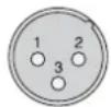
1 = ground
2 = signal ^+
3 = signal -
3-pole 6.3 mm plug
for balanced connection

T = signal +
R = signal -
S = ground
2-pole 6.3 mm plug
for unbalanced connection

T = signal
S = ground
3-pole 6.3 mm plug
for the INSERTJacks

T = Send (output)
R = Return (input)
S = ground
6.3 mm stereo plug
for the headphone connection

T = left channel
R = right channel
S = ground
Subject to technical modification.
Table des matieres
Line (canal mono): 1 mV/10 kΩ; jack 6,35, sym.
Line (canal stereo) .. 10mV / 10k jack 6,35,sym.
Interface USB: .USB 2.0 (Full Speed)
Bande passante: 20-20 000 Hz
Interfaccia USB: .USB 2.0 (Full Speed)
USB-interface*: USB 2.0 (Full Speed)
Frequentiebereik: 20-20 000 Hz
THD: <0.05%
Signaal/Ruis-verhouding: >74dB (A-gemeten)
Overspraat: -63 dB
Equalizer
Low Cut-filter: 75 Hz
T = signal +
R = sigmaal -
S=massa
Line (canal mono): . . . 1 mV/10 kΩ;
Jack 6,3 mm, sim.
Line (canal estereo): .10 mV/10 kΩ;
Jack 6,3 mm, sim.
T = senal +
R = serial -
S = masa